Page 421 of 2890

B2M0764A
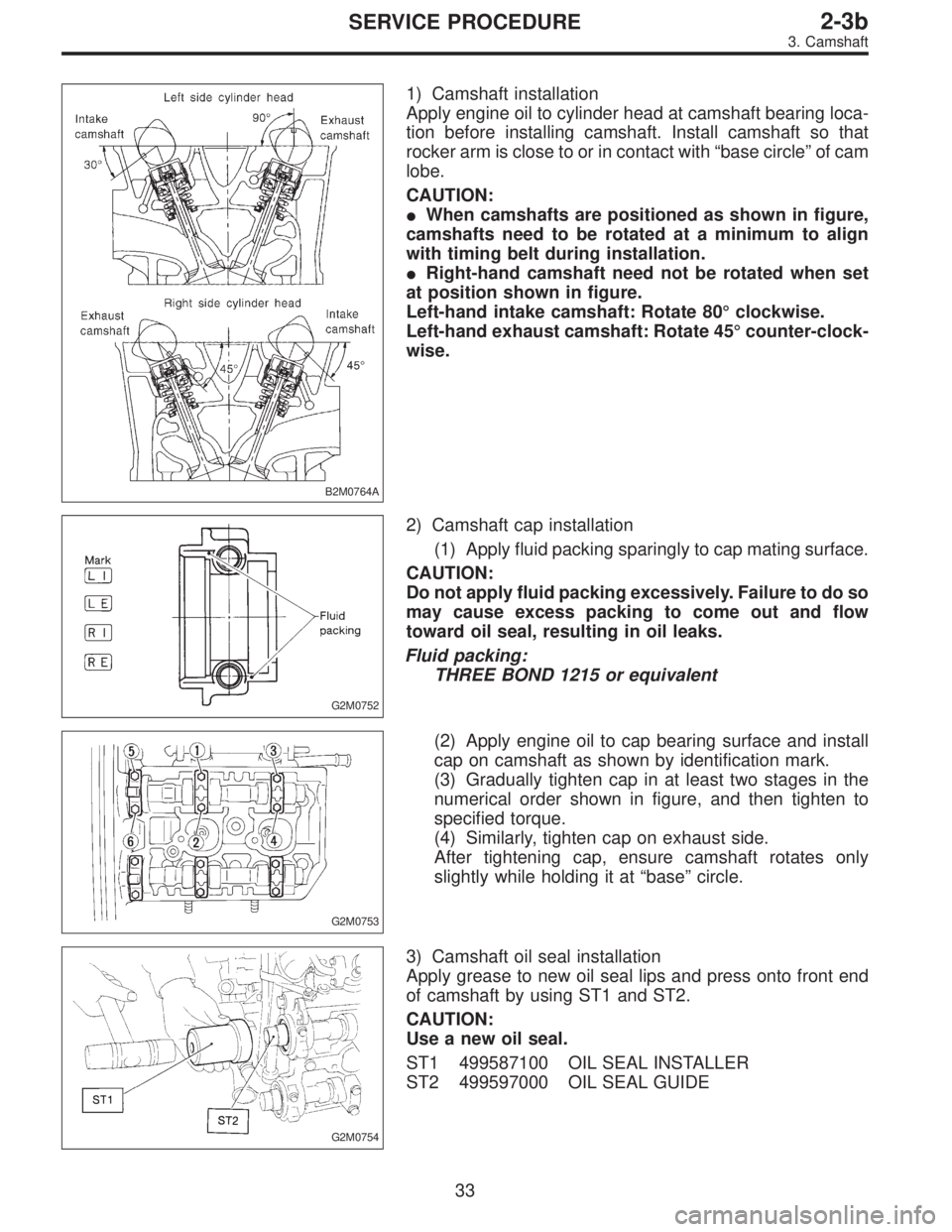
1) Camshaft installation
Apply engine oil to cylinder head at camshaft bearing loca-
tion before installing camshaft. Install camshaft so that
rocker arm is close to or in contact with“base circle”of cam
lobe.
CAUTION:
�When camshafts are positioned as shown in figure,
camshafts need to be rotated at a minimum to align
with timing belt during installation.
�Right-hand camshaft need not be rotated when set
at position shown in figure.
Left-hand intake camshaft: Rotate 80°clockwise.
Left-hand exhaust camshaft: Rotate 45°counter-clock-
wise.
G2M0752
2) Camshaft cap installation
(1) Apply fluid packing sparingly to cap mating surface.
CAUTION:
Do not apply fluid packing excessively. Failure to do so
may cause excess packing to come out and flow
toward oil seal, resulting in oil leaks.
Fluid packing:
THREE BOND 1215 or equivalent
G2M0753
(2) Apply engine oil to cap bearing surface and install
cap on camshaft as shown by identification mark.
(3) Gradually tighten cap in at least two stages in the
numerical order shown in figure, and then tighten to
specified torque.
(4) Similarly, tighten cap on exhaust side.
After tightening cap, ensure camshaft rotates only
slightly while holding it at“base”circle.
G2M0754
3) Camshaft oil seal installation
Apply grease to new oil seal lips and press onto front end
of camshaft by using ST1 and ST2.
CAUTION:
Use a new oil seal.
ST1 499587100 OIL SEAL INSTALLER
ST2 499597000 OIL SEAL GUIDE
33
2-3bSERVICE PROCEDURE
3. Camshaft
Page 422 of 2890
G2M0755
4) Rocker cover installation
(1) Install gasket on rocker cover.
Install peripheral gasket and ignition coil gasket.
(2) Apply fluid packing to four front open edges of
peripheral gasket.
Fluid packing:
THREE BOND 1215 or equivalent
(3) Install rocker cover on cylinder head. Ensure gas-
ket is properly positioned during installation.
5) Install ignition coil.
6) Install cam angle sensor.
7) Similarly, install parts on right-hand side.
2. RELATED PARTS
Install timing belt, camshaft sprockets and related parts.
34
2-3bSERVICE PROCEDURE
3. Camshaft
Page 423 of 2890
4. Cylinder Head
A: REMOVAL
1. INTAKE MANIFOLD
1) Remove V-belt.
2) Remove generator, air conditioner compressor and
brackets.
3) Remove hoses and tubes from cylinder block.
4) Disconnect each connector and/or remove connector
bracket.
5) Remove coolant filler tank.
6) Remove intake manifold assembly and gasket.
7) Remove water pipe.
8) Remove crank angle sensor, cam angle sensor and
knock sensor.
9) Remove timing belt, camshaft sprockets and related
parts.
10) Remove rocker cover, camshafts and related parts.
2. CYLINDER HEAD
B2M0770A
35
2-3bSERVICE PROCEDURE
4. Cylinder Head
Page 433 of 2890
2) Install camshaft sprockets, timing belt and related parts.
B2M0702
B2M0703
3) Install engine coolant pipe.
CAUTION:
Use new gaskets.
45
2-3bSERVICE PROCEDURE
4. Cylinder Head
Page 435 of 2890
5. Cylinder Block
A: REMOVAL
1. RELATED PARTS
1) Remove timing belt, camshaft sprockets and related
parts.
B2M0702
47
2-3bSERVICE PROCEDURE
5. Cylinder Block
Page 462 of 2890
B2M0390A
(2) Apply fluid packing to matching surface of oil pump.
Fluid packing:
THREE BOND 1215 or equivalent
(3) Install oil pump on cylinder block. Be careful not to
damage oil seal during installation.
CAUTION:
�Do not forget to install O-ring and seal when install-
ing oil pump.
�Align flat surface of oil pump’s inner rotor with
crankshaft before installation.
G2M0628
9) Install engine coolant pump and gasket.
CAUTION:
�Be sure to use a new gasket.
�When installing engine coolant pump, tighten bolts
in two stages in numerical sequence as shown in Fig-
ure.
10) Install engine coolant pipe.
11) Install oil filter.
2. RELATED PARTS
1) Install cylinder heads.
2) Install camshafts, rocker cover and related parts.
3) Install camshaft sprockets, timing belt and related parts.
74
2-3bSERVICE PROCEDURE
5. Cylinder Block
Page 464 of 2890

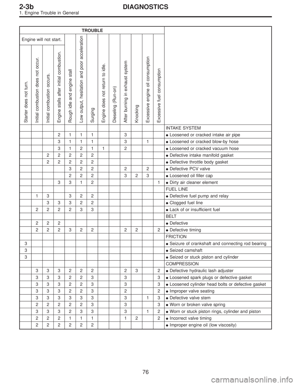
TROUBLE
Engine will not start.
Rough idle and engine stall
Low output, hesitation and poor acceleration
Surging
Engine does not return to idle.
Dieseling (Run-on)
After burning in exhaust system
Knocking
Excessive engine oil consumption
Excessive fuel consumption Starter does not turn.
Initial combustion does not occur.
Initial combustion occurs.
Engine stalls after initial combustion.
INTAKE SYSTEM
2111 3�Loosened or cracked intake air pipe
3111 3 1�Loosened or cracked blow-by hose
31211 2�Loosened or cracked vacuum hose
22222�Defective intake manifold gasket
22222�Defective throttle body gasket
322 2 2�Defective PCV valve
222 323�Loosened oil filler cap
3312 1�Dirty air cleaner element
FUEL LINE
13 322�Defective fuel pump and relay
33322�Clogged fuel line
222233�Lack of or insufficient fuel
BELT
222�Defective
222322 22 2�Defective timing
FRICTION
3�Seizure of crankshaft and connecting rod bearing
3�Seized camshaft
3�Seized or stuck piston and cylinder
COMPRESSION
333222 23 2�Defective hydraulic lash adjuster
333223 3 3�Loosened spark plugs or defective gasket
333223 3 3�Loosened cylinder head bolts or defective gasket
333223 2 2�Improper valve seating
333333 3 13�Defective valve stem
222223 3 3�Worn or broken valve spring
333233 3 12�Worn or stuck piston rings, cylinder and piston
222111 12 2�Incorrect valve timing
222222�Improper engine oil (low viscosity)
76
2-3bDIAGNOSTICS
1. Engine Trouble in General
Page 467 of 2890

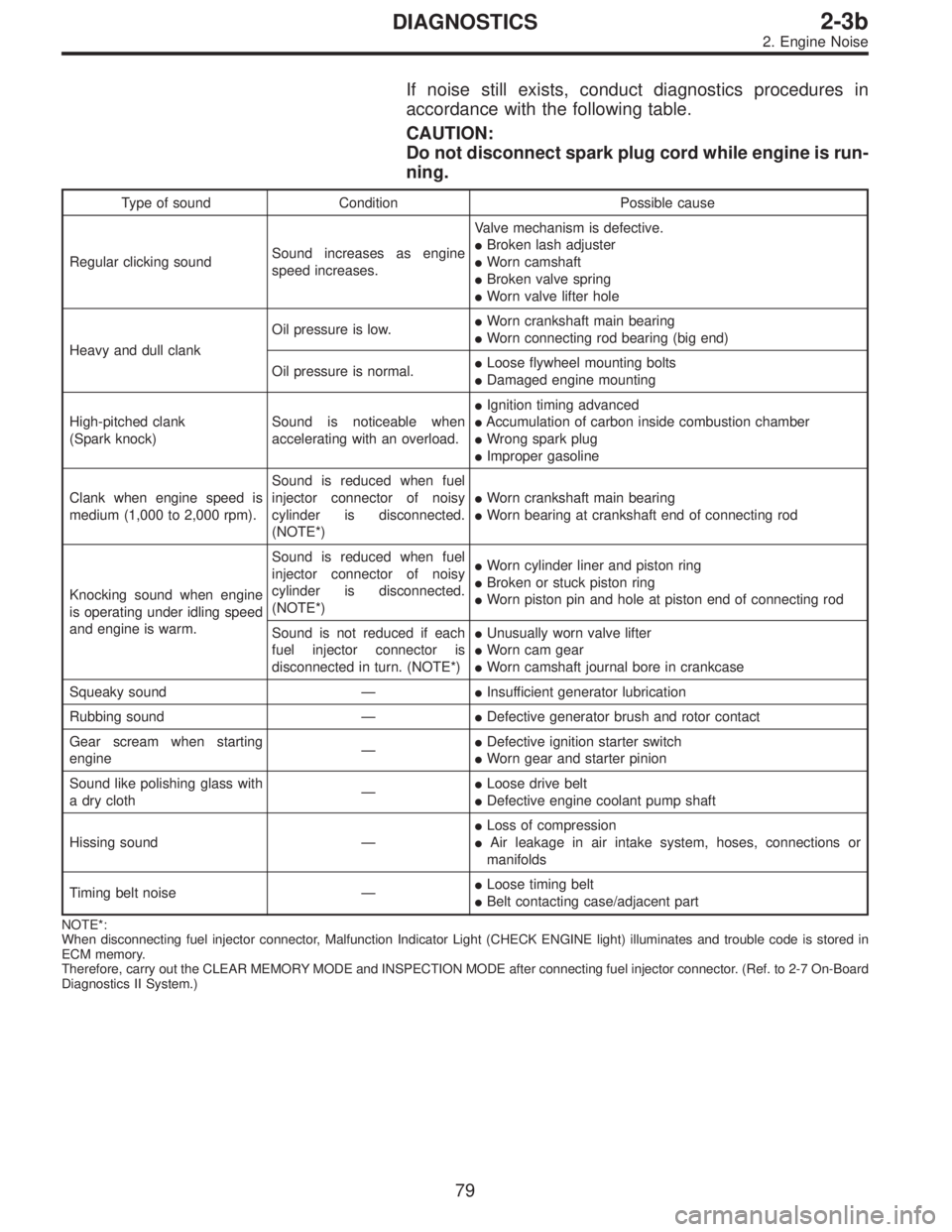
If noise still exists, conduct diagnostics procedures in
accordance with the following table.
CAUTION:
Do not disconnect spark plug cord while engine is run-
ning.
Type of sound Condition Possible cause
Regular clicking soundSound increases as engine
speed increases.Valve mechanism is defective.
�Broken lash adjuster
�Worn camshaft
�Broken valve spring
�Worn valve lifter hole
Heavy and dull clankOil pressure is low.�Worn crankshaft main bearing
�Worn connecting rod bearing (big end)
Oil pressure is normal.�Loose flywheel mounting bolts
�Damaged engine mounting
High-pitched clank
(Spark knock)Sound is noticeable when
accelerating with an overload.�Ignition timing advanced
�Accumulation of carbon inside combustion chamber
�Wrong spark plug
�Improper gasoline
Clank when engine speed is
medium (1,000 to 2,000 rpm).Sound is reduced when fuel
injector connector of noisy
cylinder is disconnected.
(NOTE*)�Worn crankshaft main bearing
�Worn bearing at crankshaft end of connecting rod
Knocking sound when engine
is operating under idling speed
and engine is warm.Sound is reduced when fuel
injector connector of noisy
cylinder is disconnected.
(NOTE*)�Worn cylinder liner and piston ring
�Broken or stuck piston ring
�Worn piston pin and hole at piston end of connecting rod
Sound is not reduced if each
fuel injector connector is
disconnected in turn. (NOTE*)�Unusually worn valve lifter
�Worn cam gear
�Worn camshaft journal bore in crankcase
Squeaky sound—�Insufficient generator lubrication
Rubbing sound—�Defective generator brush and rotor contact
Gear scream when starting
engine—�Defective ignition starter switch
�Worn gear and starter pinion
Sound like polishing glass with
a dry cloth—�Loose drive belt
�Defective engine coolant pump shaft
Hissing sound—�Loss of compression
�Air leakage in air intake system, hoses, connections or
manifolds
Timing belt noise—�Loose timing belt
�Belt contacting case/adjacent part
NOTE*:
When disconnecting fuel injector connector, Malfunction Indicator Light (CHECK ENGINE light) illuminates and trouble code is stored in
ECM memory.
Therefore, carry out the CLEAR MEMORY MODE and INSPECTION MODE after connecting fuel injector connector. (Ref. to 2-7 On-Board
Diagnostics II System.)
79
2-3bDIAGNOSTICS
2. Engine Noise