Page 1384 of 2890
2. Basic Information
1) The combination of moisture and refrigerant forms acid,
therefore, moisture should not be allowed to enter the
refrigerant.
2) Refrigerant oil readily absorbs moisture, therefore, keep
refrigerant oil containers tightly capped.
3) The process of evacuating the system is performed to
remove small amounts of moisture. This is accomplished
by lowering the pressure inside the system, which allows
the moisture to boil off, in much the same way that a pot
of water will boil away to nothing given enough time. The
evacuation process does not suck the moisture out of the
system.
4) A minimum level of vacuum must be reached to satis-
factorily evacuate the system. This minimum level of
vacuum depends on the temperature inside the system.
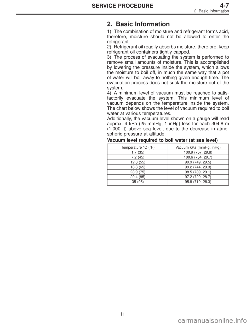
The chart below shows the level of vacuum required to boil
water at various temperatures.
Additionally, the vacuum level shown on a gauge will read
approx. 4 kPa (25 mmHg, 1 inHg) less for each 304.8 m
(1,000 ft) above sea level, due to the decrease in atmo-
spheric pressure at altitude.
Vacuum level required to boil water (at sea level)
Temperature°C(°F) Vacuum kPa (mmHg, inHg)
1.7 (35) 100.9 (757, 29.8)
7.2 (45) 100.6 (754, 29.7)
12.8 (55) 99.9 (749, 29.5)
18.3 (65) 99.2 (744, 29.3)
23.9 (75) 98.5 (739, 29.1)
29.4 (85) 97.2 (729, 28.7)
35 (95) 95.8 (719, 28.3)
11
4-7SERVICE PROCEDURE
2. Basic Information
Page 1396 of 2890
8. Leak Testing
The following points should be kept in mind when conduct-
ing a refrigerant leak test.
1) The A/C system to be tested must have an adequate
refrigerant charge to begin with.
2) The area where the leak test is conducted must be free
of wind and drafts, with still air being the ideal condition.
3) The atmosphere where the leak test is conducted must
be free of refrigerant contamination.
4) Operate the A/C system for approx. 10 minutes, then
turn the engine off an begin the leak test.
5) Refrigerant gas is heavier than air, therefore always
hold the probe below the connection being tested.
6) When checking for a leak along a length of hose or
tube, the leak detector probe must be moved slowly,
approx. 25 mm (1 in) per second making sure probe does
not come in contact with the component being tested.
7) When checking for a leak at a certain point, the leak
detector probe must be held at that point for at least 5
seconds.
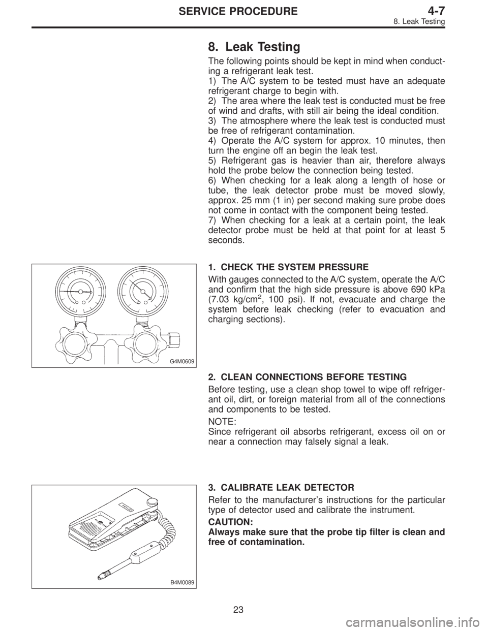
G4M0609
1. CHECK THE SYSTEM PRESSURE
With gauges connected to the A/C system, operate the A/C
and confirm that the high side pressure is above 690 kPa
(7.03 kg/cm
2, 100 psi). If not, evacuate and charge the
system before leak checking (refer to evacuation and
charging sections).
2. CLEAN CONNECTIONS BEFORE TESTING
Before testing, use a clean shop towel to wipe off refriger-
ant oil, dirt, or foreign material from all of the connections
and components to be tested.
NOTE:
Since refrigerant oil absorbs refrigerant, excess oil on or
near a connection may falsely signal a leak.
B4M0089
3. CALIBRATE LEAK DETECTOR
Refer to the manufacturer’s instructions for the particular
type of detector used and calibrate the instrument.
CAUTION:
Always make sure that the probe tip filter is clean and
free of contamination.
23
4-7SERVICE PROCEDURE
8. Leak Testing
Page 1399 of 2890
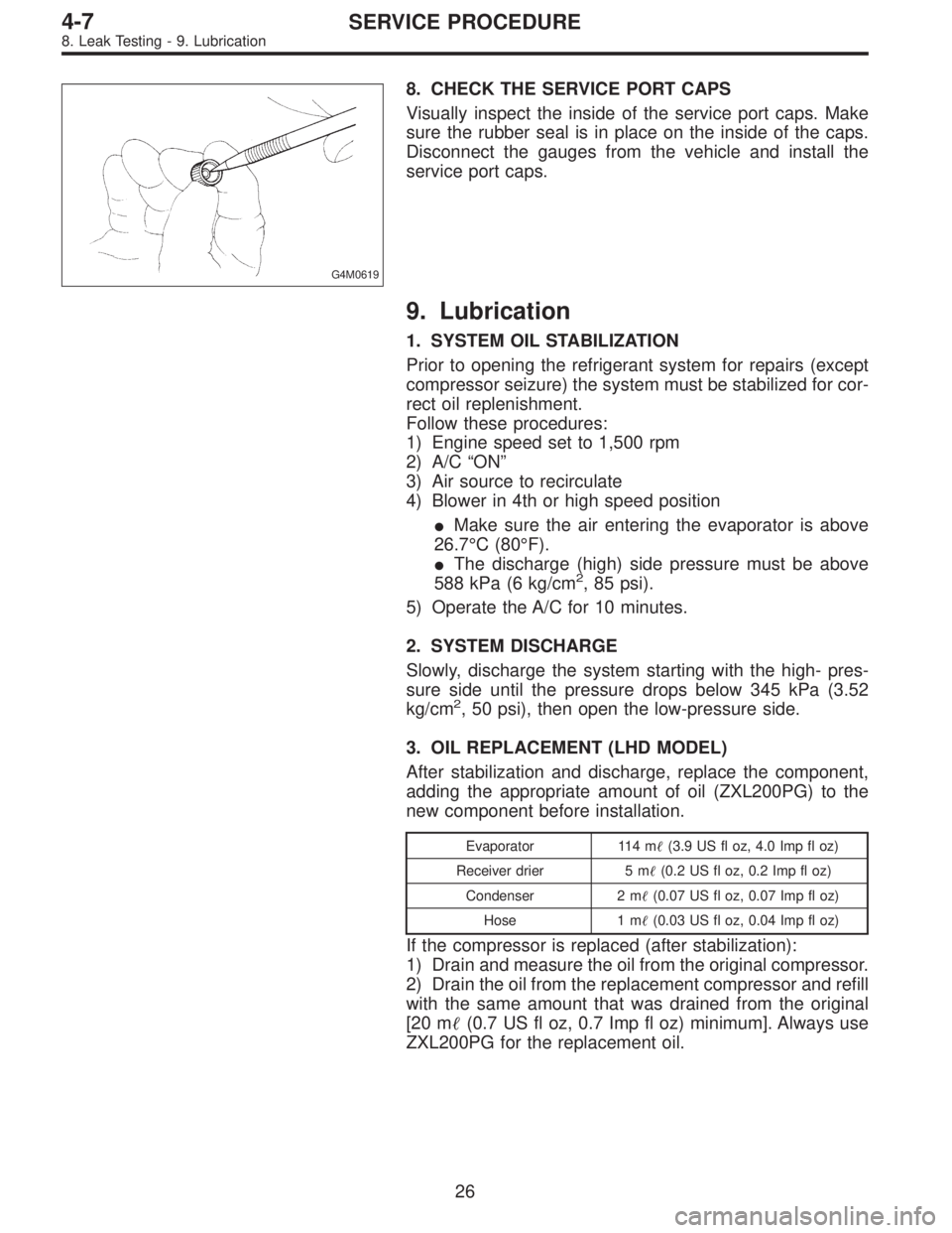
G4M0619
8. CHECK THE SERVICE PORT CAPS
Visually inspect the inside of the service port caps. Make
sure the rubber seal is in place on the inside of the caps.
Disconnect the gauges from the vehicle and install the
service port caps.
9. Lubrication
1. SYSTEM OIL STABILIZATION
Prior to opening the refrigerant system for repairs (except
compressor seizure) the system must be stabilized for cor-
rect oil replenishment.
Follow these procedures:
1) Engine speed set to 1,500 rpm
2) A/C“ON”
3) Air source to recirculate
4) Blower in 4th or high speed position
�Make sure the air entering the evaporator is above
26.7°C (80°F).
�The discharge (high) side pressure must be above
588 kPa (6 kg/cm
2, 85 psi).
5) Operate the A/C for 10 minutes.
2. SYSTEM DISCHARGE
Slowly, discharge the system starting with the high- pres-
sure side until the pressure drops below 345 kPa (3.52
kg/cm
2, 50 psi), then open the low-pressure side.
3. OIL REPLACEMENT (LHD MODEL)
After stabilization and discharge, replace the component,
adding the appropriate amount of oil (ZXL200PG) to the
new component before installation.
Evaporator 114 m�(3.9 US fl oz, 4.0 Imp fl oz)
Receiver drier 5 m�(0.2 US fl oz, 0.2 Imp fl oz)
Condenser 2 m�(0.07 US fl oz, 0.07 Imp fl oz)
Hose 1 m�(0.03 US fl oz, 0.04 Imp fl oz)
If the compressor is replaced (after stabilization):
1) Drain and measure the oil from the original compressor.
2) Drain the oil from the replacement compressor and refill
with the same amount that was drained from the original
[20 m�(0.7 US fl oz, 0.7 Imp fl oz) minimum]. Always use
ZXL200PG for the replacement oil.
26
4-7SERVICE PROCEDURE
8. Leak Testing - 9. Lubrication
Page 1400 of 2890
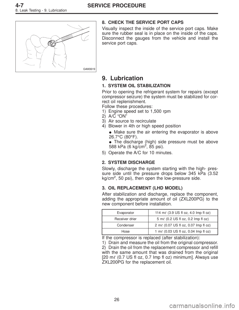
G4M0619
8. CHECK THE SERVICE PORT CAPS
Visually inspect the inside of the service port caps. Make
sure the rubber seal is in place on the inside of the caps.
Disconnect the gauges from the vehicle and install the
service port caps.
9. Lubrication
1. SYSTEM OIL STABILIZATION
Prior to opening the refrigerant system for repairs (except
compressor seizure) the system must be stabilized for cor-
rect oil replenishment.
Follow these procedures:
1) Engine speed set to 1,500 rpm
2) A/C“ON”
3) Air source to recirculate
4) Blower in 4th or high speed position
�Make sure the air entering the evaporator is above
26.7°C (80°F).
�The discharge (high) side pressure must be above
588 kPa (6 kg/cm
2, 85 psi).
5) Operate the A/C for 10 minutes.
2. SYSTEM DISCHARGE
Slowly, discharge the system starting with the high- pres-
sure side until the pressure drops below 345 kPa (3.52
kg/cm
2, 50 psi), then open the low-pressure side.
3. OIL REPLACEMENT (LHD MODEL)
After stabilization and discharge, replace the component,
adding the appropriate amount of oil (ZXL200PG) to the
new component before installation.
Evaporator 114 m�(3.9 US fl oz, 4.0 Imp fl oz)
Receiver drier 5 m�(0.2 US fl oz, 0.2 Imp fl oz)
Condenser 2 m�(0.07 US fl oz, 0.07 Imp fl oz)
Hose 1 m�(0.03 US fl oz, 0.04 Imp fl oz)
If the compressor is replaced (after stabilization):
1) Drain and measure the oil from the original compressor.
2) Drain the oil from the replacement compressor and refill
with the same amount that was drained from the original
[20 m�(0.7 US fl oz, 0.7 Imp fl oz) minimum]. Always use
ZXL200PG for the replacement oil.
26
4-7SERVICE PROCEDURE
8. Leak Testing - 9. Lubrication
Page 1405 of 2890
B4M0760A
B: REMOVAL
1) Disconnect ground cable from battery.
2) Discharge refrigerant using refrigerant recovery system.
(1) Fully close low-pressure valve of manifold gauge.
(2) Connect low-pressure charging hose of manifold
gauge to low-pressure service valve.
(3) Open low-pressure manifold gauge valve slightly,
and slowly discharge refrigerant from system.
CAUTION:
Do not allow refrigerant to rush out. Otherwise, com-
pressor oil will be discharged along with refrigerant.
B4M0761A
3) Remove low-pressure hose�1(Flexible hose Ps) and
high-pressure hose�
2(Flexible hose Pd).
CAUTION:
�Be careful not to lose O-ring of low-pressure hose.
�Plug the opening to prevent foreign matter from
entering.
G4M0624
4) Remove compressor belt cover and alternator belt
cover.
Remove bolts which secure belt covers.
G4M0625
5) Remove alternator V-belt.
Loosen lock bolt on alternator bracket. Turn adjusting bolt
and remove V-belt.
31
4-7SERVICE PROCEDURE
11. Compressor
Page 1408 of 2890
G4M0634
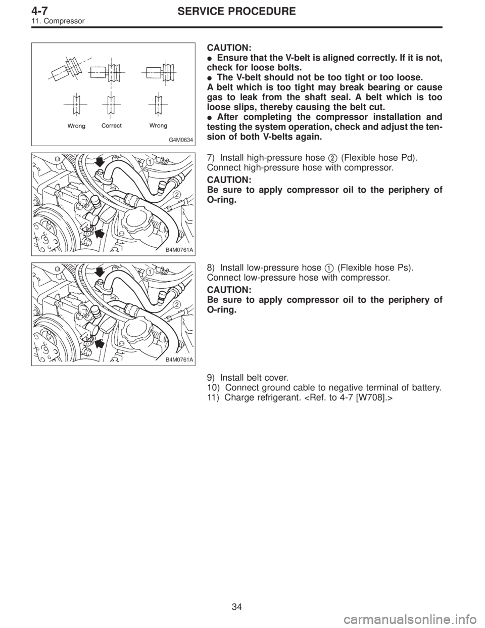
CAUTION:
�Ensure that the V-belt is aligned correctly. If it is not,
check for loose bolts.
�The V-belt should not be too tight or too loose.
A belt which is too tight may break bearing or cause
gas to leak from the shaft seal. A belt which is too
loose slips, thereby causing the belt cut.
�After completing the compressor installation and
testing the system operation, check and adjust the ten-
sion of both V-belts again.
B4M0761A
7) Install high-pressure hose�2(Flexible hose Pd).
Connect high-pressure hose with compressor.
CAUTION:
Be sure to apply compressor oil to the periphery of
O-ring.
B4M0761A
8) Install low-pressure hose�1(Flexible hose Ps).
Connect low-pressure hose with compressor.
CAUTION:
Be sure to apply compressor oil to the periphery of
O-ring.
9) Install belt cover.
10) Connect ground cable to negative terminal of battery.
11) Charge refrigerant.
34
4-7SERVICE PROCEDURE
11. Compressor
Page 1409 of 2890
B4M0095
12. Condenser
A: REMOVAL AND INSTALLATION
1) Disconnect battery negative terminal.
2) Discharge refrigerant using refrigerant recovery system.
3) Remove front grille.
G2M0375
4) Remove canister from bracket.
CAUTION:
�Do not disconnect hose from canister.
�Insert air vent hose of canister into the hole on body.
B4M0096A
5) Remove the radiator upper bracket of both side.
6) Disconnect high-pressure hose�
1and high-pressure
pipe�
2from condenser.
B4M0097
7) Remove the two bolts which secure condenser. While
lifting condenser, remove it through space between radia-
tor and radiator panel.
B4M0098A
8) The condenser should be installed in the reverse order
in which it was removed.
When installing the condenser, pay attention to the follow-
ing:
CAUTION:
Before connecting the pipe, be sure to apply oil to the
periphery of O-ring.
35
4-7SERVICE PROCEDURE
12. Condenser
Page 1410 of 2890
![SUBARU LEGACY 1996 Service Repair Manual NOTE:
After installing condenser, ensure that guide on lower side
of condenser is inserted into hole in radiator panel. Tighten
attaching bolts.
9) Charge refrigerant. <Ref. to 4-7 [W708].>
B: INSPECT](/manual-img/17/57433/w960_57433-1409.png "SUBARU LEGACY 1996 Service Repair Manual NOTE:
After installing condenser, ensure that guide on lower side
of condenser is inserted into hole in radiator panel. Tighten
attaching bolts.
9) Charge refrigerant. <Ref. to 4-7 [W708].>
B: INSPECT")
NOTE:
After installing condenser, ensure that guide on lower side
of condenser is inserted into hole in radiator panel. Tighten
attaching bolts.
9) Charge refrigerant.
B: INSPECTION
1) Make sure the condenser fins are free from dust and
insects. If the fins are clogged, clean by blowing air or
water through them.
NOTE:
To prevent dust and water from getting into the condenser,
this work must be done when the condenser is installed in
an actual vehicle.
2) Check the condenser to see if it shows any sign of oil.
Should oil ooze or gas leak from the condenser replace it
with a new one.
G4M0640
13. Receiver Drier
A: REMOVAL AND INSTALLATION
1) Disconnect battery negative terminal.
2) Discharge refrigerant using refrigerant recovery system.
3) Disconnect pressure switch harness�
1.
4) Disconnect pipes�
2.
5) Remove mounting bolt�
3and remove receiver drier.
CAUTION:
The receiver drier contains a desiccant. Be sure to put
a blind plug in the detached receiver drier to protect it
from moisture.
6) Install the receiver drier in the reverse order of removal.
7) Charge refrigerant.
36
4-7SERVICE PROCEDURE
12. Condenser - 13. Receiver Drier
![SUBARU LEGACY 1996 Service Repair Manual B4M0760A
B: REMOVAL
1) Disconnect ground cable from battery.
2) Discharge refrigerant using refrigerant recovery system.
<Ref. to 4-7 [W601].>
(1) Fully close low-pressure valve of manifold gauge.
(2)](/manual-img/17/57433/w960_57433-1404.png "SUBARU LEGACY 1996 Service Repair Manual B4M0760A
B: REMOVAL
1) Disconnect ground cable from battery.
2) Discharge refrigerant using refrigerant recovery system.
<Ref. to 4-7 [W601].>
(1) Fully close low-pressure valve of manifold gauge.
(2)")
![SUBARU LEGACY 1996 Service Repair Manual B4M0095
12. Condenser
A: REMOVAL AND INSTALLATION
1) Disconnect battery negative terminal.
2) Discharge refrigerant using refrigerant recovery system.
<Ref. to 4-7 [W601].>
3) Remove front grille.
G2M](/manual-img/17/57433/w960_57433-1408.png "SUBARU LEGACY 1996 Service Repair Manual B4M0095
12. Condenser
A: REMOVAL AND INSTALLATION
1) Disconnect battery negative terminal.
2) Discharge refrigerant using refrigerant recovery system.
<Ref. to 4-7 [W601].>
3) Remove front grille.
G2M")