Page 60 of 2890
2-7
tT5o21
ON-BOARD
DIAGNOSTICS
II
SYSTEM
5
.
Specified
Data
CT
il
Signal
(V)
Content
onnector
erm
na
I9nition
SW
ON
Note
No
.
No
.
(Engine
OFF)Engine
ON
(Idling)
Rear
oxygen
sensor
B84
37
0-1
.0
0-1
.0
-
heater
signal
AT
diagnosis
input
B84
80
Less
than
1
.-
.
More
Less
than
1
+-+
MoreWaveform
signal
than4
than
4
GND
(sensors)
B84
200
0
-
i
B
469
GND
(
njectors)
80
0
-
95
GND
(ignition
system)
B84
940
0
-
ND
l
B
4
19
(powersupp
y)
G
800
-
46
17
GND
(control
systems)
B84
00
-
18
GND
(oxygen
sensor
B84
4200
heater)
2
.
ENGINECONDITION
DATA
Content
Specified
data
i
fl
M
1.7
-
3
.3
(g/sec)
:
Idling
r
ass
a
ow
7
.1
-
14
.2
(g/sec)
:
2,500
rpm
racing
E
il
d
1.6
-
2
.9
(%)
:
Idling
ng
neoa
6
.4
-
12
.8
(%)
:
2,500
rpm
racing
Measuring
condition
:
"
After
warm-up
theengine
.
"
Gear
position
is
in
"N"
or
"P"
position
.
"
A/C
is
turned
OFF
.
All
accessory
switches
are
turned
OFF
.
46
Page 61 of 2890
![SUBARU LEGACY 1996 Service Repair Manual 2-7
(T6A1]
ON-BOARD
DIAGNOSTICS
II
SYSTEM
6
.
Wiring
Diagram
and
Wiring
Harness
Combination
mete
Tachometer
il0
:e
i
12
:
b
Malfunction
I
il4
:c
indicator
~--
lamp
Speedometer
circuit
ill
Main SUBARU LEGACY 1996 Service Repair Manual 2-7
(T6A1]
ON-BOARD
DIAGNOSTICS
II
SYSTEM
6
.
Wiring
Diagram
and
Wiring
Harness
Combination
mete
Tachometer
il0
:e
i
12
:
b
Malfunction
I
il4
:c
indicator
~--
lamp
Speedometer
circuit
ill
Main](/manual-img/17/57433/w960_57433-60.png)
2-7
(T6A1]
ON-BOARD
DIAGNOSTICS
II
SYSTEM
6
.
Wiring
Diagram
and
Wiring
Harness
Combination
mete
Tachometer
il0
:e
i
12
:
b
Malfunction
I
il4
:c
indicator
~--
lamp
Speedometer
circuit
ill
Main
relay
~`1
o
B47
Twi
sted
wire
0
846
E
:~~M
R
Fuel
pump
relay
6
.
Wiring
Diagram
and
Wiring
Harness
A
:
WIRING
DIAGRAM
1
.
ENGINE
ELECTRICAL
SYSTEM
To
Power
Supply
Routing
FB-20
~
FUSE
Na
15
MB-3
SBF-2
FB-4
FUSE
Na
l6
ST
IG
SW
FB-22
FUSE
Na
15
I2
B37
i3
B39
S
.
M
.
J
.
[Refer
to
foldout
page
.)
R58R57RIS
Fuel
pump
Inhibitor
switch
812
F45
B62
Check
connector
a
v
879
mvov-~o
M
PPm
M
f~
vrn
f~
Om
.O
Enginecontro
I
B84
module
14001
B97B17
Rl
Vehicle
speed
sensor
2
g7
(B
I
ac
k)
i
It
(g
)(Green)
Rl5
(B
I
ec
k)
R58
1212
123
34
3456
456
i
14
(L
1
ght
gray)
I101l2
(L
I
ght
gray)
12345678910111213
123456789101111314116
50
B47
(Brown)
B12
(Gray)
1
2
1
23
4345
67
8
5
69
1011
12
F45
B79
(Gray)
1
23
4567
8
910
11121R314
(2
i3
(Brown)
2345
6789
1234
678910
1'1
11
1
1
1
13
1
14
1
15
1
16
1
17
1
18
1
19
1
20,011
1
12
1
13
1
14
1
1
51
16
1
17
1
18
1
19
1
20
1
21
1
22
1
BUR10-02A
Page 63 of 2890
2-7
[rsai]
ON-BOARD
DIAGNOSTICS
II
SYSTEM
6
.
Wiring
Diagram
and
Wiring
Harness
Engine
Shield
Boost
Throttle
coolant
joint
sensorposition
Knock
temperature
E
.G.R
.
connector
sensor
sensor
sensor
solenoid
BB3
FF
R
I
B2
H
I
(
:
P
P
(:
9
)
PEE
(
ED
EH
(
9
)
....
E2
821
Ref
.
toAT
control
system
.
Enginecontro
I
B84
module
....
822
E3
B3
Mess
air
flowsensor
.
.
..
..
..
III
(Ca
I
(forn
(a
mode
I)
arri
813
m
EE
Ignitor
O
(Brown)
El8
E8
(Brown)
(B
I
eck)
B2
El3
(Brown)
12
123
B3
(Grey)(
ED
(Grey)
1234
123456
52
Ell
(Gray)
123
B2l
(L
i
ght
gray)
1234
5678
910U12
Ell
Ignition
coil
B83
1234
B22
CL
i
ght
gray)
1234
5678
9
1011
12
13141516
BUR10-02C
Page 64 of 2890
![SUBARU LEGACY 1996 Service Repair Manual
ON-BOARD
DIAGNOSTICS
II
SYSTEM
[TSAy]
2-7
6
.
Wiring
Diagram
and
Wiring
Harness
CrankshaftCamshaftpositionposition
sensorsensor
E10
I
E15
....
.
.
...
1
11
_..
.
..
._.J
r--
..
U)
33
3
:
E
1
--- SUBARU LEGACY 1996 Service Repair Manual
ON-BOARD
DIAGNOSTICS
II
SYSTEM
[TSAy]
2-7
6
.
Wiring
Diagram
and
Wiring
Harness
CrankshaftCamshaftpositionposition
sensorsensor
E10
I
E15
....
.
.
...
1
11
_..
.
..
._.J
r--
..
U)
33
3
:
E
1
---](/manual-img/17/57433/w960_57433-63.png)
ON-BOARD
DIAGNOSTICS
II
SYSTEM
[TSAy]
2-7
6
.
Wiring
Diagram
and
Wiring
Harness
CrankshaftCamshaftpositionposition
sensorsensor
E10
I
E15
....
.
.
...
1
11
_..
.
..
._.J
r--
..
U)
33
3
:
E
1
------------
-----------
-
m
M
~
B20
V1
1I1III
_
1
y
P
Iu+IN'"I
INI
II
Engine
control
B84
module
v
M
~~l
c
o
JJ
a
J
L
m
m
J3
F
Y
J
J
J
J
P1
H
JJ
L
m
;
~N
E3
4
}E17
~~
Eb
~
E16
~
E5
3E7
~~
A
E4
#4
#3#2
#1
Fuel
(nJector
Ely
(Dark
grey)
E10
(Gray)
12
E4
(B
I
ue)
E7
(Gray)
B20
(L
i
ght
grey)
12
123
123
456
BUR10-02D
Idle
air
control
Purge
control
solenoid
valve
solenoid
valve
B84
(Light
blue)
1
2
LI3
4
U
5
6U78U
1112
0
1314
1J
1516
1718
1920
21
22
23
24
252627282930
1
31
1
32
1
33
1
34
1
35
1
36~
1
37
1
38
1
39
1
401
41
1421
43
44
45
1
46
1
47
1
48
1
49
1
5
0
1
51
1
52
1
53
1
54,
~
5
1
56
1
57
1
8
626364
65
bb
6768
69
7071
7273
74
75
7
6
77
78
79
80
81
B283
1
84
1
65
1
86
1
87
1
88
1
89
1
90
1
91
1
92
1
93
1
94
1
95
1
96
(L
(
ght
gray)
E5
El6
(L
(
ght
gray)
(Darkgray)
E6
(O
(Dark
grey)
12
53
Page 66 of 2890

ON-BOARD
DIAGNOSTICS
II
SYSTEM
[Tsn2i
2-7
6
.
Wiring
Diagram
and
Wiring
Harness
FWD
switch
(AWD)
B9
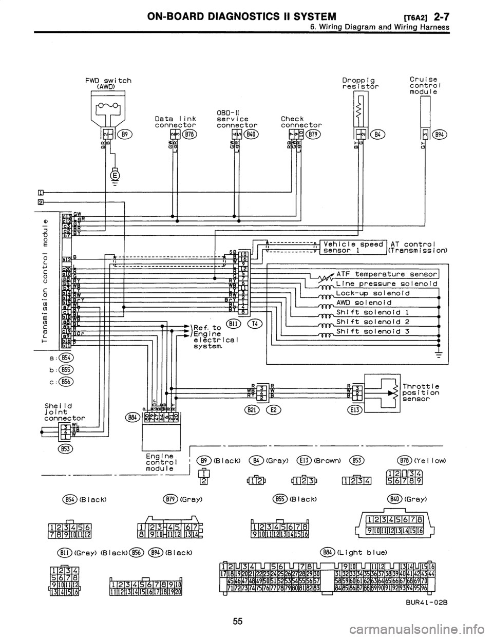
ffl
Droppig
Cruise
resistor
cont
rol
modu
le
OBD-II
Data
link
serviceCheck
connectorconnectorconnector
B78
ERB40
0
B79
m
B4
E
K
E
)
w
7
OEs
o
-
-
-
------------------
-
------
-
-
L
a
....
c
H
0
U
It
C
Y
0
.N
;W
Rr
06
N
BI1
T41
Ref
.
to
/Engine
electrical
system
.
a
:
B54
b
:
B55
c
:
856
She
ild
joint
connector
884
~
WK
LZIM
WL
B53
Engine
control
B9(B
I
ac
k)
module
1
2
854
(B
I
ac
k)
B79
(Grey)
1
23456
1
23
45
67
7
1
8
1
9101112
8
910
1112
1
13
1
14
r,
Bll
(Grey)
(B
I
ac
k)
B56894
(B
I
aCk)
34
S
78
D
q
Oil
2
9
Pl
.
12131415,91617
la19
110
I
5
16
1
3
14
1111121131141151161171161191201
AT
contro
I
------------
a
,,
Vehicle
speed
i(Transmission)
___
_____
__
__
sensor
1
ATF
temperature
sensor
Line
pressuresolenoid
Lock-up
solenoid
AWD
solenoid
Shift
solenoid
1
Shift
solenoid
2
Shift
solenoid
3
R3
Throttle
~-Cz'1
R~l
position
sensor
B2l
E2
El3
O
(Gray)
E13
(Brown)
853
B78
(Y
e
II
ow)
12
123
1234
56789
B55
(B
I
ack)
(
ED
(Grey)
12345678
12345678
9~011t213141St6
91111213141516
864
(L
i
ght
b
I
ue)
12
345678
9l0
lll21314
1516
I7l8l9
20
2122
23
24
2627282930
3132
3334
35
3637383940
4142
43
44
454647
1
48
1
49
~
0
1
51
2
15
3
15
4
~
5
1
56
15
7
8596061626364656667686970
7172
73
1
74
1
75
1
76
1
77
78
1
79
1
60
1
81
B
1
132
1
83d
8485
86
87888990
9192
93
94
9596
BUR41-02B
55
Page 78 of 2890
ON-BOARD
DIAGNOSTICS
II
SYSTEM
[T9G0]
2-7
9
.
Diagnostics
for
Engine
Starting
Failure
G
:
CRANKSHAFT
POSITION
SENSOR
CIRCUIT
WIRING
DIAGRAM
:
B84
B20
E1
ECM
''--------
E10
Crankshaft
position
sensor
O
Crankshaft
sprocket
E84
B20
E10
1
23
456
12
1
23456
7
8
1718190
21
2
2324
28290
45
1
46
1
4
7
1
48
1
49
150
11
1
521
53
1
54
55
5657
7
1
721731
1
4
175
11
6
/
80
81
8283
B2M0529
NOTE
:
For
the
diagnostic
procedure
on
crankshaft
position
sen-
sor
circuit,
referto
2-7
[T1OZ0]*2
.
67
Page 79 of 2890
2-7
[T9H0]
ON-BOARD
DIAGNOSTICS
II
SYSTEM
9
.
Diagnostics
for
Engine
StartingFailure
H
:
CAMSHAFT
POSITION
SENSOR
CIRCUIT
WIRING
DIAGRAM
:
B84
B20
E1
------------
ECM
T
..........
.r
E15
Camshaft
pulley
Camshaft
position
sensor
B84
B20E15
0
123
456
i2
82M0530
NOTE
:
For
the
diagnostic
procedure
on
crankshaft
position
sen-
0AA0]*2
.
sor
circuit,
referto
2-7
[T1
~
1
2
11
3
2
4
21
u
5
4
6
u
7
8
29
u
0
4546
47484950
51
5253545556
51
1
469
80
1
82
3
68
Page 80 of 2890

ON-BOARD
DIAGNOSTICS
II
SYSTEM
[Tyooyl
2-7
10
.
General
Diagnostics
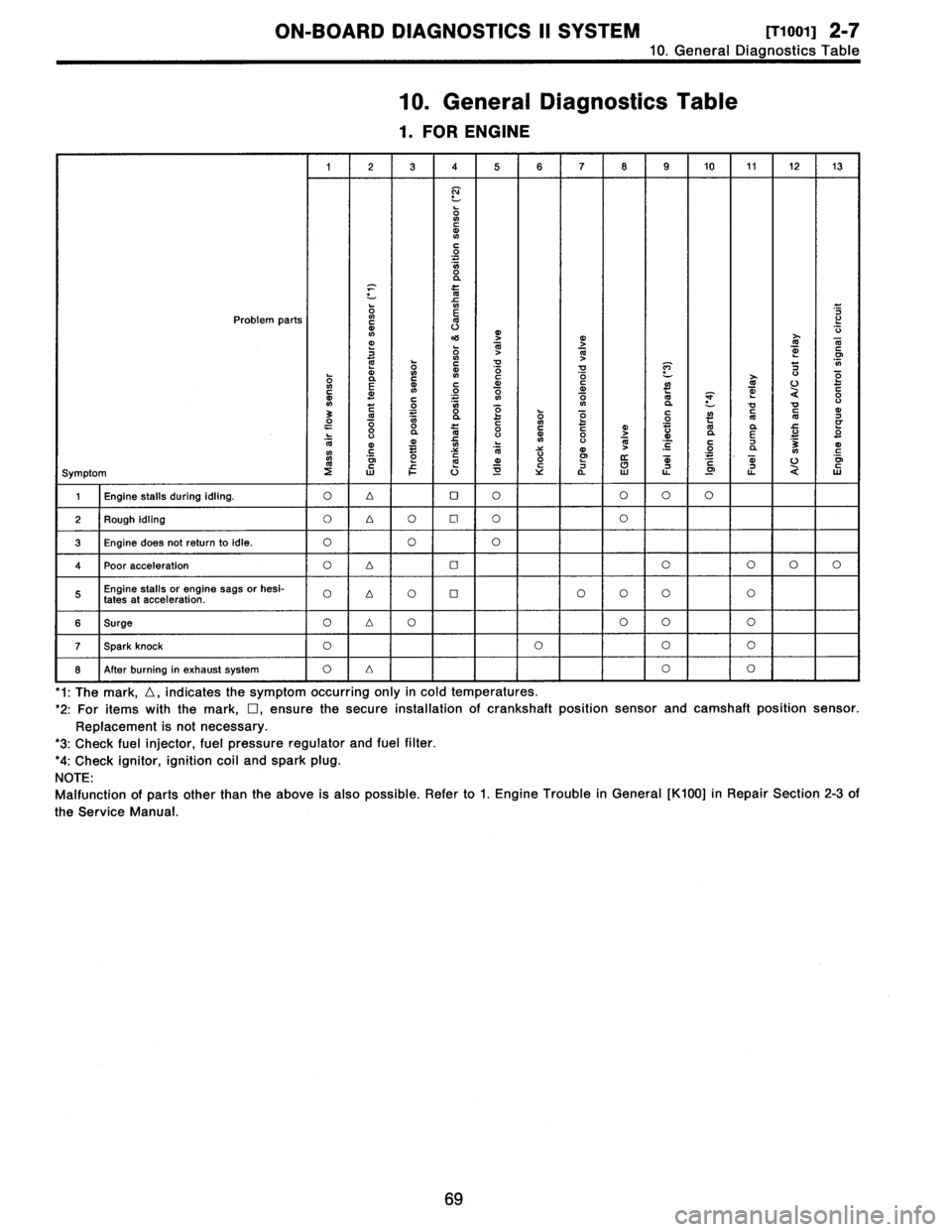
Table
10
.
General
Diagnostics
Table
1
.
FOR
ENGINE
1
23
4
5678
9
10
11
1213
N
ONCdN
C
O
O
a
x
m
Problem
parts
`o
m
v
mj
4'S
O
1>j
T
N
dm
G
~
ON
41
m
~
!d
V
P]
7
0
E
m
~n
N
~o
C
o
O
d
~
~
U
O
c
m~
C
.
.
.
V1
ON
aVa
U
3
C~
0
"
y
dO1OyOQ
~
"O
CN
d7
O
"
0va
l0
0CdyGo
>
"
Vd
da
E
U
"
O
l0
ymC
~
O
NC
N
V
V
4)
N
~
'C
C
.2
7
a
3NmC
oi
mm
o
W
m
.
mU
o~
Symptom
2WFU~Ya
LL
.0
ti
QW
1
Engine
stalls
during
idling
.
O4OOOOO
2
Rough
idling
O
4O
Cl
OO
3
Engine
does
notreturnto
idle
.
O
OO
4Poor
acceleration
O4OOOOO
Engine
stalls
or
engine
sags
or
hesi-
O
D
OOOOOO
fates
at
acceleration
.
6
Surge
O4OOOO
T
Spark
knock
OOOO
8
After
burning
in
exhaust
system
O
Lr
I
O
I
'1
:
The
mark,
D,
indicates
the
symptom
occurring
only
in
cold
temperatures
.
'2
:
For
itemswiththe
mark,
D,ensure
the
secure
installationof
crankshaft
position
sensor
and
camshaft
position
sensor
.
Replacement
is
not
necessary
.
'3
:
Check
fuel
injector,
fuel
pressure
regulator
and
fuel
filter
.
'4
:
Check
ignitor,
ignition
coil
and
spark
plug
.
NOTE
:
Malfunction
of
partsother
than
the
above
is
also
possible
.
Refer
to
1
.
Engine
Trouble
in
General
[K100]
in
Repair
Section
2-3
of
the
Service
Manual
69