Page 1977 of 2890
�3GROUP OF #3 AND #4 CYLINDERS
: Are there faults in #3 and #4 cylinders?
NOTE:
Check the following items.
�Spark plugs
�Fuel injectors
�Ignition coil
: Go to next.
: Go to DTC P0170, 2-7 [T10P3], [T10P4] and
[T10P5].
NOTE:
If no abnormal is discovered, check for“8. F: IGNITION
SYSTEM”of #3 and #4 cylinders side.
�
4GROUP OF #1 AND #3 CYLINDERS
: Are there faults in #1 and #3 cylinders?
NOTE:
Check the following items.
�Spark plugs
�Fuel injectors
�Skipping timing belt teeth
: Go to next.
: Go to DTC P0170, 2-7 [T10P3], [T10P4] and
[T10P5].
�
5GROUP OF #2 AND #4 CYLINDERS
: Are there faults in #2 and #4 cylinders?
NOTE:
Check the following items.
�Spark plugs
�Fuel injectors
�Skipping timing belt teeth
: Go to next.
: Go to DTC P0170, 2-7 [T10P3], [T10P4] and
[T10P5].
�
6THE CYLINDER AT RANDOM
: Is the engine idle rough?
: Go to next.
: Go to DTC P0170, 2-7 [T10P3], [T10P4] and
[T10P5].
209
2-7ON-BOARD DIAGNOSTICS II SYSTEM
10. Diagnostics Chart with Trouble Code
Page 2063 of 2890
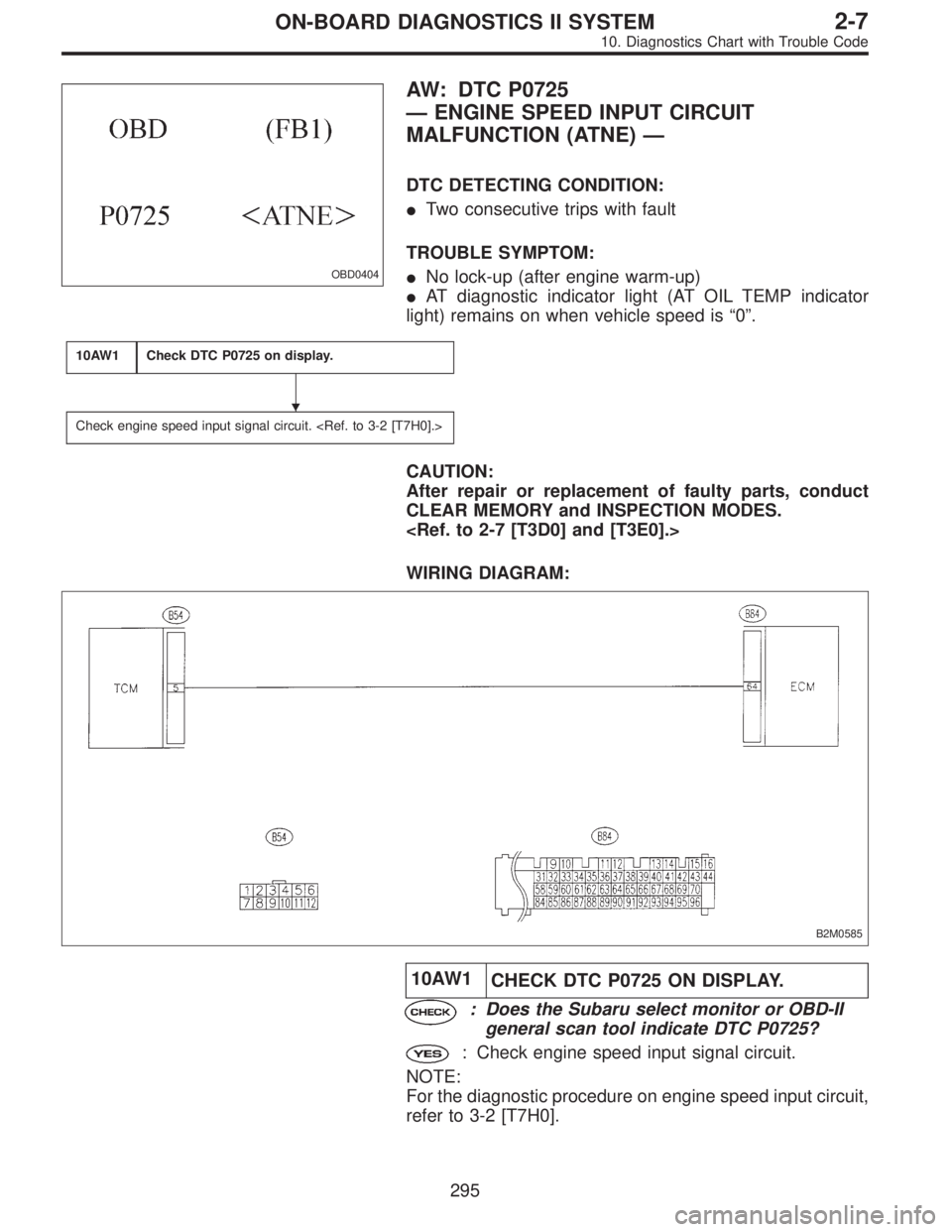
OBD0404
AW: DTC P0725
—ENGINE SPEED INPUT CIRCUIT
MALFUNCTION (ATNE)—
DTC DETECTING CONDITION:
�Two consecutive trips with fault
TROUBLE SYMPTOM:
�No lock-up (after engine warm-up)
�AT diagnostic indicator light (AT OIL TEMP indicator
light) remains on when vehicle speed is“0”.
10AW1Check DTC P0725 on display.
Check engine speed input signal circuit.
CAUTION:
After repair or replacement of faulty parts, conduct
CLEAR MEMORY and INSPECTION MODES.
WIRING DIAGRAM:
B2M0585
10AW1
CHECK DTC P0725 ON DISPLAY.
: Does the Subaru select monitor or OBD-II
general scan tool indicate DTC P0725?
: Check engine speed input signal circuit.
NOTE:
For the diagnostic procedure on engine speed input circuit,
refer to 3-2 [T7H0].
�
295
2-7ON-BOARD DIAGNOSTICS II SYSTEM
10. Diagnostics Chart with Trouble Code
Page 2142 of 2890
 Check that selector lever does not move from“N”to“R”
without pushing the bu")
G3M0717
3. OPERATION OF SHIFT SELECTOR LEVER
WARNING:
Stop the engine while checking operation of selector
lever.
1) Check that selector lever does not move from“N”to“R”
without pushing the button.
2) Check that selector lever does not move from“R”to“P”
without pushing the button.
3) Check that selector lever does not move from“P”to“R”
without pushing the button.
4) Check that selector lever does not move from“3”to“2”
without pushing the button.
3. Electrical Components Location
1. SENSOR AND CONTROL MODULE
B3M0178B
�1Throttle position sensor
�
2Dropping resistor
�
3Vehicle speed sensor 2
�
4Inhibitor switch
�
5ECM
�
6Vehicle speed sensor 1 (AWD)
�
7Vehicle speed sensor 1 (FWD)
�
8TCM�
9Data link connector (for Subaru select monitor only)
�
10Data link connector (for Subaru select monitor and OBD-II
general scan tool)
�
11Diagnosis connector
�
12Diagnosis terminal
�
13AT OIL TEMP indicator light
(AT diagnostic indicator light)
3
3-2AUTOMATIC TRANSMISSION AND DIFFERENTIAL
2. Pre-inspection - 3. Electrical Components Location
Page 2143 of 2890
 Check that selector lever does not move from“N”to“R”
without pushing the bu")
G3M0717
3. OPERATION OF SHIFT SELECTOR LEVER
WARNING:
Stop the engine while checking operation of selector
lever.
1) Check that selector lever does not move from“N”to“R”
without pushing the button.
2) Check that selector lever does not move from“R”to“P”
without pushing the button.
3) Check that selector lever does not move from“P”to“R”
without pushing the button.
4) Check that selector lever does not move from“3”to“2”
without pushing the button.
3. Electrical Components Location
1. SENSOR AND CONTROL MODULE
B3M0178B
�1Throttle position sensor
�
2Dropping resistor
�
3Vehicle speed sensor 2
�
4Inhibitor switch
�
5ECM
�
6Vehicle speed sensor 1 (AWD)
�
7Vehicle speed sensor 1 (FWD)
�
8TCM�
9Data link connector (for Subaru select monitor only)
�
10Data link connector (for Subaru select monitor and OBD-II
general scan tool)
�
11Diagnosis connector
�
12Diagnosis terminal
�
13AT OIL TEMP indicator light
(AT diagnostic indicator light)
3
3-2AUTOMATIC TRANSMISSION AND DIFFERENTIAL
2. Pre-inspection - 3. Electrical Components Location
Page 2151 of 2890
B: ABNORMAL DISPLAY ON AT OIL TEMP
INDICATOR
When any on-board diagnostic item is malfunctioning, the
display on the AT OIL TEMP indicator blinks immediately
after the engine starts.
The malfunctioning part or unit can be determined by a
trouble code during on-board diagnostic operation. Prob-
lems which occurred previously can also be identified
through the memory function.
If the AT OIL TEMP indicator does not show a problem
(although a problem is occurring), the problem can be
determined by checking the performance characteristics of
each sensor using the select monitor.
Indicator signal is as shown in the figure.
WARNING:
Warning can be noticed only when the engine is ini-
tially started.
B3M0410A
11
3-2AUTOMATIC TRANSMISSION AND DIFFERENTIAL
6. Diagnostic Chart for On-board Diagnostic System
Page 2174 of 2890
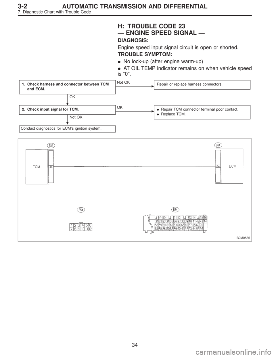
H: TROUBLE CODE 23
—ENGINE SPEED SIGNAL—
DIAGNOSIS:
Engine speed input signal circuit is open or shorted.
TROUBLE SYMPTOM:
�No lock-up (after engine warm-up)
�AT OIL TEMP indicator remains on when vehicle speed
is“0”.
1. Check harness and connector between TCM
and ECM.
OK
�Not OK
Repair or replace harness connectors.
2. Check input signal for TCM.
Not OK
�OK
�Repair TCM connector terminal poor contact.
�Replace TCM.
Conduct diagnostics for ECM’s ignition system.
B2M0585
�
�
34
3-2AUTOMATIC TRANSMISSION AND DIFFERENTIAL
7. Diagnostic Chart with Trouble Code
Page 2208 of 2890

One-way clutch (3-")
Overrunning clutch
Drive pinion
Crown gear
Axle shaft
Differential gear
Final gear
Seal pipe
Oil pump
High clutch
Band brake
Low & reverse clutch
Reverse clutch
One-way clutch (1-2)
One-way clutch (3-4)
Double oil seal
Input shaft
Output shaft
Planetary gear
Reduction gear
Drive plate
Torque converter one-way clutch
Lock-up facing
Lock-up damper
ATF deterioration
ATF level too high or too low
Differential gear oil level too high or too low
Engine performance
Engine speed signal
Parking brake mechanism
Problem parts
30 31 32 33 34 35 36 37 38 39 40 41 42 43 44 45 46 47 48 49 50 51 52 53 54 55 56 57 58 Symptom
Starter does not rotate when select lever is
in“P”or“N.”; starter rotates when select
lever is“R”,“D”,“3”or“2.”
XXXAbnormal noise when select lever is in“P”or
“N.”
X Hissing noise occurs during standing starts.
X X X X Noise occurs while driving in“D
1”range.
X X X X Noise occurs while driving in“D
2”range.
X X X Noise occurs while driving in“D
3”range.
X X X X Noise occurs while driving in“D
4”range.
XXEngine stalls while shifting from one range to
another.
Vehicle moves when select lever is in“N.”
XShock occurs when select lever is moved
from“N”to“D.”
Excessive time lag occurs when select lever
is moved from“N”to“D.”
XShock occurs when select lever is moved
from“N”to“R.”
XXExcessive time lag occurs when select lever
is moved from“N”to“R.”
XXXX X XXX X XVehicle does not start in any shift range
(engine revving up).
XVehicle does not start in any shift range
(engine stall).
XXVehicle does not start in“R”range only
(engine revving up).
XXVehicle does not start in“R”range only
(engine stall).
XVehicle does not start in“D”or“3”range
(engine revving up).
Vehicle does not start in“D”,“3”or“2”range
(engine revving up).
XVehicle does not start in“D”,“3”or“2”range
(engine stall).
Vehicle starts in“R”range only (engine rev-
ving up).
XXAcceleration during standing starts is poor
(high stall rpm).
XXXAcceleration during standing starts is poor
(low stall rpm).
XX XAcceleration is poor when select lever is in
“D”,“3”or“2”range (normal stall rpm).
XXXXAcceleration is poor when select lever is in
“R”(normal stall rpm).
XNo shift occurs from 1st to 2nd gear.
X X No shift occurs from 2nd to 3rd gear.
XNo shift occurs from 3rd to 4th gear.
No“kick-down”shifts occur.
Engine brake is not effected when select
lever is in“3”range.
30 31 32 33 34 35 36 37 38 39 40 41 42 43 44 45 46 47 48 49 50 51 52 53 54 55 56 57 58
68
3-2AUTOMATIC TRANSMISSION AND DIFFERENTIAL
9. General Diagnostic Table
Page 2209 of 2890

Problem parts
Inhibitor switch
Control module
Vehicle speed sensor 1
Vehicle speed sensor 2
Select cable
Select lever
FWD switch
Starter motor and harness
Throttle position sensor
Diagnosis switch
Accumulator (“N”—“D”)
Accumulator (2A)
Accumulator (4A)
Accumulator (3R)
ATF temperature sensor
Strainer
Duty solenoid A
Duty solenoid B
Shift solenoid 1
Shift solenoid 2
Shift solenoid 3
Control valve
Detent spring
Manual plate
Transfer clutch
Transfer valve
Transfer pipe
Duty solenoid C
Forward clutch
Symptom1234567891011121314151617181920212223242526272829
Engine brake is not effected when select
lever is in“3”or“2”range.
Engine brake is not effected when select
lever is in“1”range.X
Shift characteristics are erroneous.XXXX X X
No lock-up occurs. X X X X
Vehicle cannot be set in“D”range power
mode.XX
“D”range power mode cannot be released. X X X
Parking brake is not effected. X X
Shift lever cannot be moved or is hard to
move from“P”range.XX
Select lever is hard to move. X X X X
Select lever is too light to move (unreason-
able resistance).XX
ATF spurts out.
Differential oil spurts out.
Differential oil level changes excessively.
Odor is produced from oil supply pipe.XX
Shock occurs when select lever is moved
from“1”to“2”range.X XXXX X
Slippage occurs when select lever is moved
from“1”to“2”range.X XXXX X
Shock occurs when select lever is moved
from“2”to“3”range.XXXXXX
Slippage occurs when select lever is moved
from“2”to“3”range.XXXXXX
Shock occurs when select lever is moved
from“3”to“4”range.X X XXX X
Slippage occurs when select lever is moved
from“3”to“4”range.X X XXX X
Shock occurs when select lever is moved
from“3”to“2”range.XXXXX
Shock occurs when select lever is moved
from“D”to“1”range.XXXXX
Shock occurs when select lever is moved
from“2”to“1”range.XXXXX
Shock occurs when accelerator pedal is
released at medium speeds.XXXXX
Vibration occurs during straight-forward
operation.XX
Select lever slips out of position during
acceleration or while driving on rough terrain.XX XX
Vibration occurs during turns (tight corner
“braking”phenomenon).XXX X X XX X
Front wheel slippage occurs during standing
starts.X X X X X X XXXX
Vehicle is not set in FWD mode. X XXX X
1234567891011121314151617181920212223242526272829
69
3-2AUTOMATIC TRANSMISSION AND DIFFERENTIAL
9. General Diagnostic Table