Page 869 of 2890
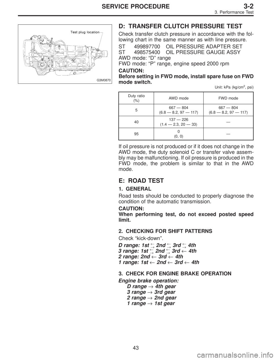
G3M0870
D: TRANSFER CLUTCH PRESSURE TEST
Check transfer clutch pressure in accordance with the fol-
lowing chart in the same manner as with line pressure.
ST 499897700 OIL PRESSURE ADAPTER SET
ST 498575400 OIL PRESSURE GAUGE ASSY
AWD mode:“D”range
FWD mode:“P”range, engine speed 2000 rpm
CAUTION:
Before setting in FWD mode, install spare fuse on FWD
mode switch.
Unit: kPa (kg/cm2, psi)
Duty ratio
(%)AWD mode FWD mode
5667—804
(6.8—8.2, 97—117)667—804
(6.8—8.2, 97—117)
40137—226
(1.4—2.3, 20—33)—
950
(0, 0)—
If oil pressure is not produced or if it does not change in the
AWD mode, the duty solenoid C or transfer valve assem-
bly may be malfunctioning. If oil pressure is produced in the
FWD mode, the problem is similar to that in the AWD
mode.
E: ROAD TEST
1. GENERAL
Road tests should be conducted to properly diagnose the
condition of the automatic transmission.
CAUTION:
When performing test, do not exceed posted speed
limit.
2. CHECKING FOR SHIFT PATTERNS
Check“kick-down”.
D range: 1st
←
→2nd←
→3rd←
→4th
3 range: 1st←
→2nd←
→3rd←4th
2 range: 2nd←3rd←4th
1 range: 1st←2nd←3rd←4th
3. CHECK FOR ENGINE BRAKE OPERATION
Engine brake operation:
D range→4th gear
3 range→3rd gear
2 range→2nd gear
1 range→1st gear
43
3-2SERVICE PROCEDURE
3. Performance Test
Page 889 of 2890
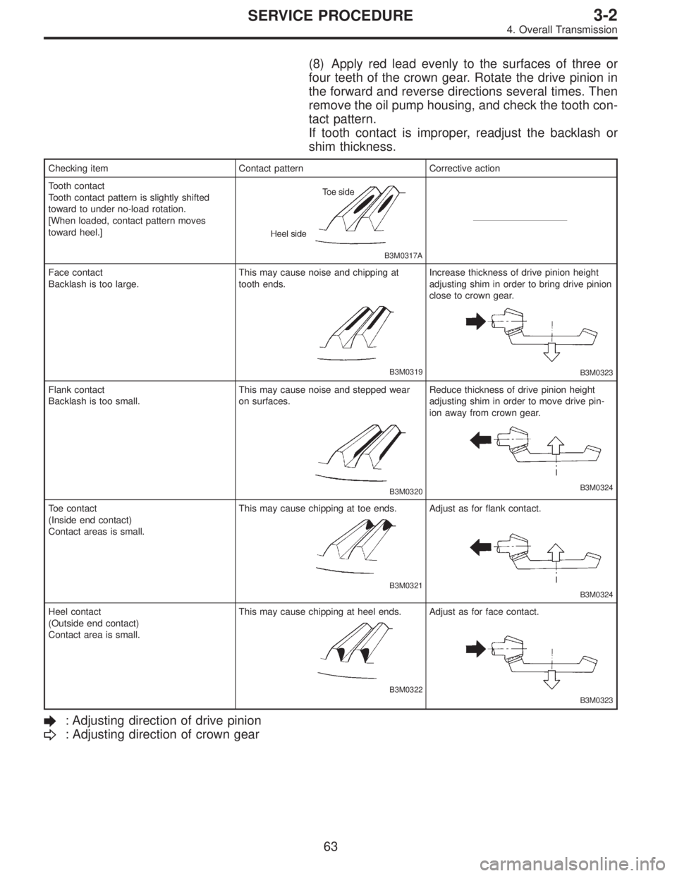
(8) Apply red lead evenly to the surfaces of three or
four teeth of the crown gear. Rotate the drive pinion in
the forward and reverse directions several times. Then
remove the oil pump housing, and check the tooth con-
tact pattern.
If tooth contact is improper, readjust the backlash or
shim thickness.
Checking item Contact pattern Corrective action
Tooth contact
Tooth contact pattern is slightly shifted
toward to under no-load rotation.
[When loaded, contact pattern moves
toward heel.]
B3M0317A
Face contact
Backlash is too large.This may cause noise and chipping at
tooth ends.
B3M0319
Increase thickness of drive pinion height
adjusting shim in order to bring drive pinion
close to crown gear.
B3M0323
Flank contact
Backlash is too small.This may cause noise and stepped wear
on surfaces.
B3M0320
Reduce thickness of drive pinion height
adjusting shim in order to move drive pin-
ion away from crown gear.
B3M0324
Toe contact
(Inside end contact)
Contact areas is small.This may cause chipping at toe ends.
B3M0321
Adjust as for flank contact.
B3M0324
Heel contact
(Outside end contact)
Contact area is small.This may cause chipping at heel ends.
B3M0322
Adjust as for face contact.
B3M0323
: Adjusting direction of drive pinion
: Adjusting direction of crown gear
63
3-2SERVICE PROCEDURE
4. Overall Transmission
Page 924 of 2890
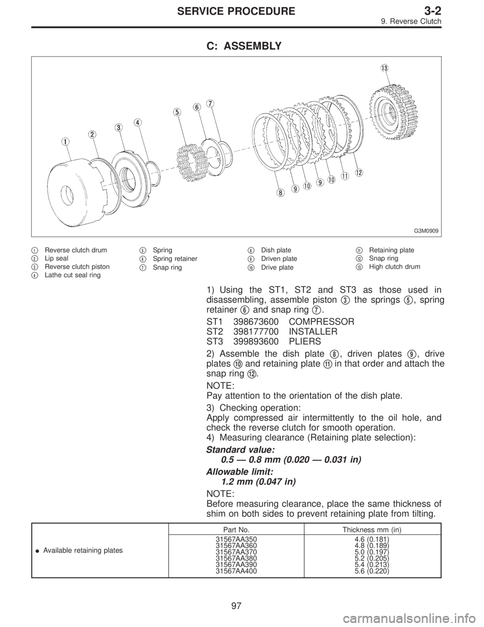
C: ASSEMBLY
G3M0909
�1Reverse clutch drum
�
2Lip seal
�
3Reverse clutch piston
�
4Lathe cut seal ring�
5Spring
�
6Spring retainer
�
7Snap ring�
8Dish plate
�
9Driven plate
�
10Drive plate�
11Retaining plate
�
12Snap ring
�
13High clutch drum
1) Using the ST1, ST2 and ST3 as those used in
disassembling, assemble piston�
3the springs�5, spring
retainer�
6and snap ring�7.
ST1 398673600 COMPRESSOR
ST2 398177700 INSTALLER
ST3 399893600 PLIERS
2) Assemble the dish plate�
8, driven plates�9, drive
plates�
10and retaining plate�11in that order and attach the
snap ring�
12.
NOTE:
Pay attention to the orientation of the dish plate.
3) Checking operation:
Apply compressed air intermittently to the oil hole, and
check the reverse clutch for smooth operation.
4) Measuring clearance (Retaining plate selection):
Standard value:
0.5—0.8 mm (0.020—0.031 in)
Allowable limit:
1.2 mm (0.047 in)
NOTE:
Before measuring clearance, place the same thickness of
shim on both sides to prevent retaining plate from tilting.
�Available retaining platesPart No. Thickness mm (in)
31567AA350
31567AA360
31567AA370
31567AA380
31567AA390
31567AA4004.6 (0.181)
4.8 (0.189)
5.0 (0.197)
5.2 (0.205)
5.4 (0.213)
5.6 (0.220)
97
3-2SERVICE PROCEDURE
9. Reverse Clutch
Page 926 of 2890
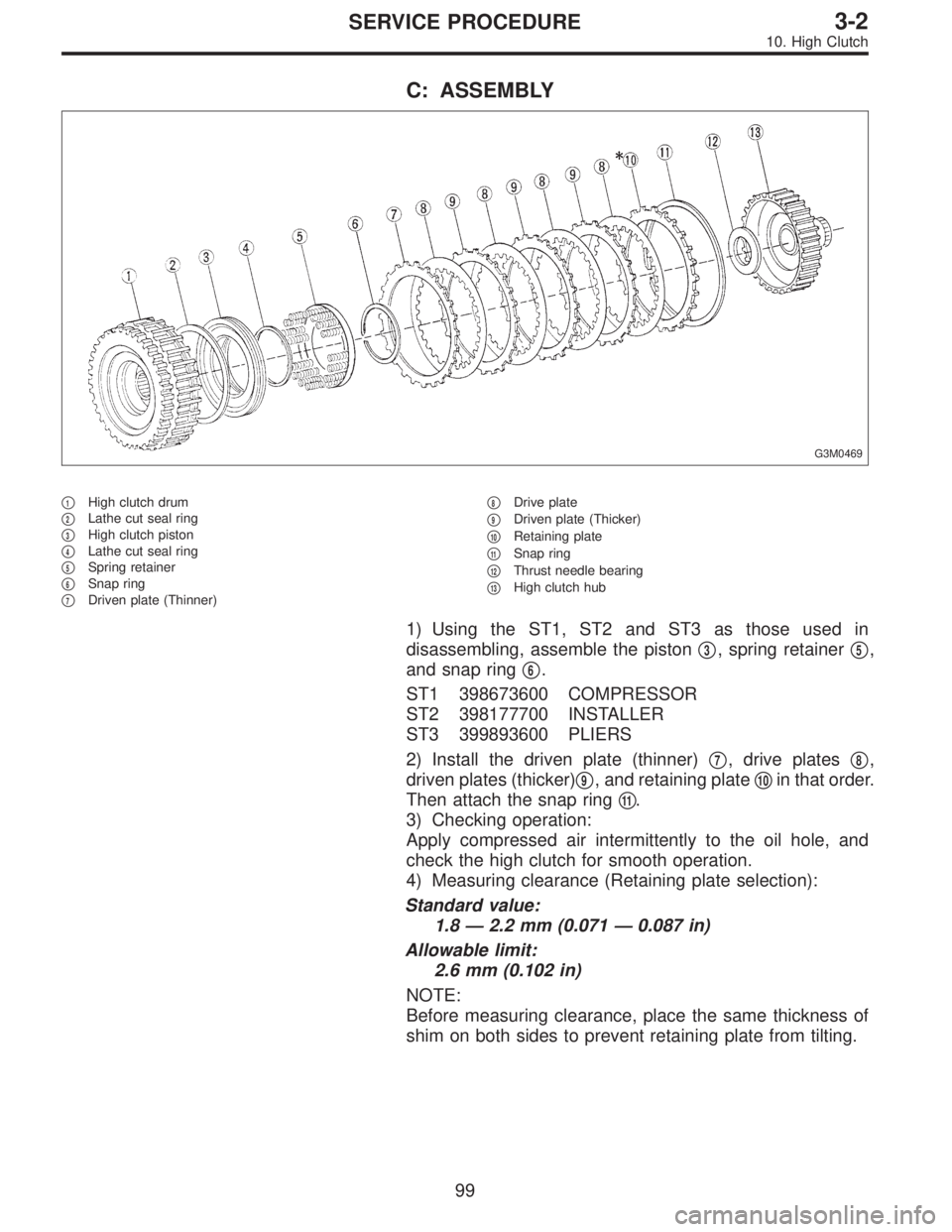
C: ASSEMBLY
G3M0469
�1High clutch drum
�
2Lathe cut seal ring
�
3High clutch piston
�
4Lathe cut seal ring
�
5Spring retainer
�
6Snap ring
�
7Driven plate (Thinner)�
8Drive plate
�
9Driven plate (Thicker)
�
10Retaining plate
�
11Snap ring
�
12Thrust needle bearing
�
13High clutch hub
1) Using the ST1, ST2 and ST3 as those used in
disassembling, assemble the piston�
3, spring retainer�5,
and snap ring�
6.
ST1 398673600 COMPRESSOR
ST2 398177700 INSTALLER
ST3 399893600 PLIERS
2) Install the driven plate (thinner)�
7, drive plates�8,
driven plates (thicker)�
9, and retaining plate�10in that order.
Then attach the snap ring�
11.
3) Checking operation:
Apply compressed air intermittently to the oil hole, and
check the high clutch for smooth operation.
4) Measuring clearance (Retaining plate selection):
Standard value:
1.8—2.2 mm (0.071—0.087 in)
Allowable limit:
2.6 mm (0.102 in)
NOTE:
Before measuring clearance, place the same thickness of
shim on both sides to prevent retaining plate from tilting.
99
3-2SERVICE PROCEDURE
10. High Clutch
Page 1025 of 2890
D: ASSEMBLY
1) Before installing coil spring, strut mount, etc., on the
strut, check for the presence of air in the dampening force
generating mechanism of the strut since air prevents
proper dampening force from being produced.
2) Checking for the presence of air
(1) Place the strut vertically with the piston rod facing
upward.
(2) Move the piston rod to the center of its entire
stroke.
(3) While holding the piston rod end with finger-tips,
move the rod up and down.
(4) If the piston rod moves at least 10 mm (0.39 in) in
step (3), purge air from the strut.
3) Air purging procedure
(1) Place the strut vertically with the piston rod facing
upward.
(2) Fully extend the piston rod.
(3) With the piston rod fully extended, place the piston
rod side down. The strut must stand vertically.
(4) Fully contract the piston rod.
(5) Repeat 3 or 4 times steps (1) through (4) above.
NOTE:
After completely purging air from the strut, be sure to place
the strut with the piston rod facing upward. If it is laid down,
check for entry of air in the strut as outlined under item 2)
above.
B4M0568A
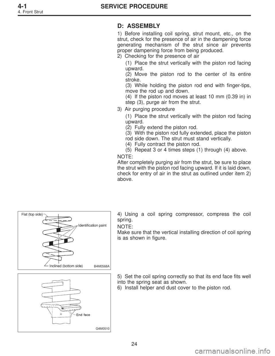
4) Using a coil spring compressor, compress the coil
spring.
NOTE:
Make sure that the vertical installing direction of coil spring
is as shown in figure.
G4M0510
5) Set the coil spring correctly so that its end face fits well
into the spring seat as shown.
6) Install helper and dust cover to the piston rod.
24
4-1SERVICE PROCEDURE
4. Front Strut
Page 1147 of 2890
![SUBARU LEGACY 1996 Service Repair Manual 5. Control Valve (Power Steering
Gearbox) [LHD model]
NOTE:
This section focuses on the disassembly and reassembly
of control valve. For the inspection and adjustment and the
service procedures for as SUBARU LEGACY 1996 Service Repair Manual 5. Control Valve (Power Steering
Gearbox) [LHD model]
NOTE:
This section focuses on the disassembly and reassembly
of control valve. For the inspection and adjustment and the
service procedures for as](/manual-img/17/57433/w960_57433-1146.png)
5. Control Valve (Power Steering
Gearbox) [LHD model]
NOTE:
This section focuses on the disassembly and reassembly
of control valve. For the inspection and adjustment and the
service procedures for associated parts, refer to“Steering
Gearbox”.
G4M0136
�1Power cylinder
�
2Cylinder
�
3Rack piston
�
4Rack axle
�
5Input shaft�
6Torsion bar
�
7Valve housing
�
8Valve body
�
9Control valve�
10Pipe B
�
11Pipe A
�
12Pinion
�
13Pinion axle
A: CHECKING OIL LEAKING POINTS
1. OIL LEAKING POINTS
1) If leak point is other than a, b, c, or d, perform check
step 5) in 4-3 [W5A2] before dismounting gearbox from
vehicle. If gearbox is dismounted without confirming where
the leak is, it must be mounted again to locate the leak
point.
2) Even if the location of the leak can be easily found by
observing the leaking condition, it is necessary to thor-
oughly remove the oil from the suspected portion and turn
the steering wheel from lock to lock about 30 to 40 times
with engine running, then make comparison of the sus-
pected portion between immediately after and several
hours after this operation.
3) Before starting oil leak repair work, be sure to clean the
gearbox, hoses, pipes, and surrounding parts. After com-
pleting repair work, clean these areas again.
40
4-3SERVICE PROCEDURE
5. Control Valve (Power Steering Gearbox) [LHD model]
Page 1156 of 2890
![SUBARU LEGACY 1996 Service Repair Manual 6. Control Valve (Power Steering
Gearbox) [RHD model]
NOTE:
This section focuses on the disassembly and reassembly
of control valve. For the inspection and adjustment and the
service procedures for as SUBARU LEGACY 1996 Service Repair Manual 6. Control Valve (Power Steering
Gearbox) [RHD model]
NOTE:
This section focuses on the disassembly and reassembly
of control valve. For the inspection and adjustment and the
service procedures for as](/manual-img/17/57433/w960_57433-1155.png)
6. Control Valve (Power Steering
Gearbox) [RHD model]
NOTE:
This section focuses on the disassembly and reassembly
of control valve. For the inspection and adjustment and the
service procedures for associated parts, refer to“Steering
Gearbox”.
B4M0668A
A: CHECKING OIL LEAKING POINTS
1. OIL LEAKING POINTS
1) If leak point is other than a, b, c, or d, perform check
step 5) in 4-3 [W6A2] before dismounting gearbox from
vehicle. If gearbox is dismounted without confirming where
the leak is, it must be mounted again to locate the leak
point.
2) Even if the location of the leak can be easily found by
observing the leaking condition, it is necessary to thor-
oughly remove the oil from the suspected portion and turn
the steering wheel from lock to lock about 30 to 40 times
with engine running, then make comparison of the sus-
pected portion between immediately after and several
hours after this operation.
3) Before starting oil leak repair work, be sure to clean the
gearbox, hoses, pipes, and surrounding parts. After com-
pleting repair work, clean these areas again.
49
4-3SERVICE PROCEDURE
6. Control Valve (Power Steering Gearbox) [RHD model]
Page 1189 of 2890
10) Check the fluid leakage at flare nuts after turning
steering wheel from lock to lock with engine running.
CAUTION:
�Before checking, wipe off any fluid on flare nuts and
piping.
�In case the fluid leaks from flare nut, it is caused by
dust (or the like) and/or damage between flare and
tapered seat in piping.
�So remove the flare nut, tighten again it to the speci-
fied torque after cleaning flare and tapered seat. If flare
or tapered seat is damaged, replace it with a new one.
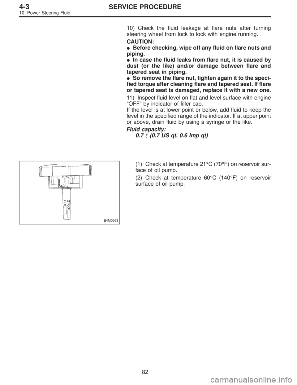
11) Inspect fluid level on flat and level surface with engine
“OFF”by indicator of filler cap.
If the level is at lower point or below, add fluid to keep the
level in the specified range of the indicator. If at upper point
or above, drain fluid by using a syringe or the like.
Fluid capacity:
0.7�(0.7 US qt, 0.6 Imp qt)
B4M0563
(1) Check at temperature 21°C (70°F) on reservoir sur-
face of oil pump.
(2) Check at temperature 60°C (140°F) on reservoir
surface of oil pump.
82
4-3SERVICE PROCEDURE
10. Power Steering Fluid