Page 1892 of 2890
DTC
No.Abbreviation
(Subaru select monitor)Item Page
P0500 VSP Vehicle speed sensor malfunction 266
P0505 ISC Idle control system malfunction 269
P0506 ISC
—L Idle control system RPM lower than expected 276
P0507 ISC
—H Idle control system RPM higher than expected 277
P0600—Serial communication link malfunction 278
P0601 RAM Internal control module memory check sum error 281
P0703 ATBRK Brake switch input malfunction 283
P0705 ATRNG Transmission range sensor circuit malfunction 286
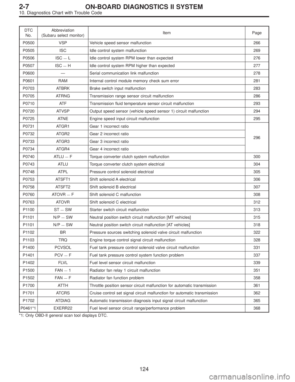
P0710 ATF Transmission fluid temperature sensor circuit malfunction 293
P0720 ATVSP Output speed sensor (vehicle speed sensor 1) circuit malfunction 294
P0725 ATNE Engine speed input circuit malfunction 295
P0731 ATGR1 Gear 1 incorrect ratio
296 P0732 ATGR2 Gear 2 incorrect ratio
P0733 ATGR3 Gear 3 incorrect ratio
P0734 ATGR4 Gear 4 incorrect ratio
P0740 ATLU
—F Torque converter clutch system malfunction 300
P0743 ATLU Torque converter clutch system electrical 304
P0748 ATPL Pressure control solenoid electrical 305
P0753 ATSFT1 Shift solenoid A electrical 306
P0758 ATSFT2 Shift solenoid B electrical 307
P0760 ATOVR
—F Shift solenoid C malfunction 308
P0763 ATOVR Shift solenoid C electrical 312
P1100 ST
—SW Starter switch circuit malfunction 313
P1101 N/P
—SW Neutral position switch circuit malfunction [MT vehicles] 315
P1101 N/P
—SW Neutral position switch circuit malfunction [AT vehicles] 318
P1102 BR Pressure sources switching solenoid valve circuit malfunction 322
P1103 TRQ Engine torque control signal circuit malfunction 328
P1400 PCVSOL Fuel tank pressure control solenoid valve circuit malfunction 331
P1401 PCV
—F Fuel tank pressure control system function problem 337
P1402 FLVL Fuel level sensor circuit malfunction 339
P1500 FAN
—1 Radiator fan relay 1 circuit malfunction 351
P1502 FAN
—F Radiator fan function problem 358
P1700 ATTH Throttle position sensor circuit malfunction for automatic transmission 361
P1701 ATCRS Cruise control set signal circuit malfunction for automatic transmission 362
P1702 ATDIAG Automatic transmission diagnosis input signal circuit malfunction 365
P0461*1 EXERR22 Fuel level sensor circuit range/performance problem 368
*1: Only OBD-II general scan tool displays DTC.
124
2-7ON-BOARD DIAGNOSTICS II SYSTEM
10. Diagnostics Chart with Trouble Code
Page 2061 of 2890
OBD0380
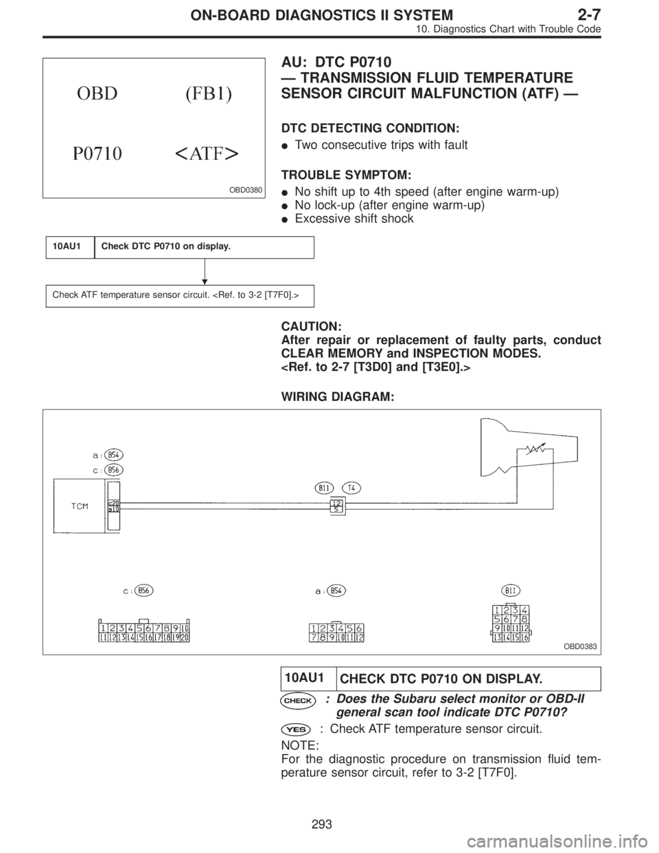
AU: DTC P0710
—TRANSMISSION FLUID TEMPERATURE
SENSOR CIRCUIT MALFUNCTION (ATF)—
DTC DETECTING CONDITION:
�Two consecutive trips with fault
TROUBLE SYMPTOM:
�No shift up to 4th speed (after engine warm-up)
�No lock-up (after engine warm-up)
�Excessive shift shock
10AU1Check DTC P0710 on display.
Check ATF temperature sensor circuit.
CAUTION:
After repair or replacement of faulty parts, conduct
CLEAR MEMORY and INSPECTION MODES.
WIRING DIAGRAM:
OBD0383
10AU1
CHECK DTC P0710 ON DISPLAY.
: Does the Subaru select monitor or OBD-II
general scan tool indicate DTC P0710?
: Check ATF temperature sensor circuit.
NOTE:
For the diagnostic procedure on transmission fluid tem-
perature sensor circuit, refer to 3-2 [T7F0].
�
293
2-7ON-BOARD DIAGNOSTICS II SYSTEM
10. Diagnostics Chart with Trouble Code
Page 2855 of 2890
Connector Connecting to
No. Pole Color Area No. Name
B30 24 * C-1 D1 Front door cord LH
B31 7 Yellow C-1 AB1 SRS (Airbag) harness
B32 3 Black C-1 Turn & hazard module
B33 4 Brown B-1 Diode (Brake fluid level)
B34 3 * B-1 Diode (Door warning)
B35 2 Black B-1 Diode (Step light)
B36 22 Black C-1 i1
Instrument panel wiring
harness B37 22 * C-1 i2
B38 22 Brown C-1 i3
B39 20 Blue C-1 i4
B40 16 Gray C-2 OBD-II service connector
B41 2 * C-2 Power window circuit breaker
B42 4 * C-2Power window and sunroof
relay
B43 6 Black C-2 Illumination control module
B44 8 * C-2 Seat belt timer
B45 4 * B-1 R53 Sunroof cord
B46 4 Green B-1 Fuel pump relay
B47 6 Brown B-1 Main relay
B48 4 Blue B-1 Front fog light relay
B49 3 Black B-1 Horn relay
B50 4 * B-1 Blower relay
B51 11 Gray B-1
F/B
B52 12 Gray B-1
B53 4 * B-2 Shield joint connector (AT)
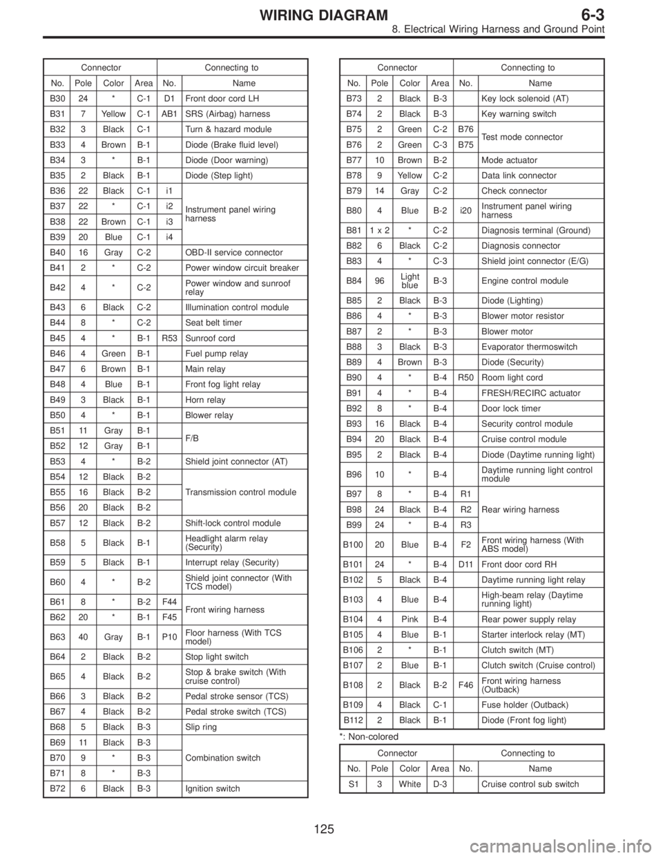
B54 12 Black B-2
Transmission control module B55 16 Black B-2
B56 20 Black B-2
B57 12 Black B-2 Shift-lock control module
B58 5 Black B-1Headlight alarm relay
(Security)
B59 5 Black B-1 Interrupt relay (Security)
B60 4 * B-2Shield joint connector (With
TCS model)
B61 8 * B-2 F44
Front wiring harness
B62 20 * B-1 F45
B63 40 Gray B-1 P10Floor harness (With TCS
model)
B64 2 Black B-2 Stop light switch
B65 4 Black B-2Stop & brake switch (With
cruise control)
B66 3 Black B-2 Pedal stroke sensor (TCS)
B67 4 Black B-2 Pedal stroke switch (TCS)
B68 5 Black B-3 Slip ring
B69 11 Black B-3
Combination switch B70 9 * B-3
B71 8 * B-3
B72 6 Black B-3 Ignition switchConnector Connecting to
No. Pole Color Area No. Name
B73 2 Black B-3 Key lock solenoid (AT)
B74 2 Black B-3 Key warning switch
B75 2 Green C-2 B76
Test mode connector
B76 2 Green C-3 B75
B77 10 Brown B-2 Mode actuator
B78 9 Yellow C-2 Data link connector
B79 14 Gray C-2 Check connector
B80 4 Blue B-2 i20Instrument panel wiring
harness
B81 1 x 2 * C-2 Diagnosis terminal (Ground)
B82 6 Black C-2 Diagnosis connector
B83 4 * C-3 Shield joint connector (E/G)
B84 96Light
blueB-3 Engine control module
B85 2 Black B-3 Diode (Lighting)
B86 4 * B-3 Blower motor resistor
B87 2 * B-3 Blower motor
B88 3 Black B-3 Evaporator thermoswitch
B89 4 Brown B-3 Diode (Security)
B90 4 * B-4 R50 Room light cord
B91 4 * B-4 FRESH/RECIRC actuator
B92 8 * B-4 Door lock timer
B93 16 Black B-4 Security control module
B94 20 Black B-4 Cruise control module
B95 2 Black B-4 Diode (Daytime running light)
B96 10 * B-4Daytime running light control
module
B97 8 * B-4 R1
Rear wiring harness B98 24 Black B-4 R2
B99 24 * B-4 R3
B100 20 Blue B-4 F2Front wiring harness (With
ABS model)
B101 24 * B-4 D11 Front door cord RH
B102 5 Black B-4 Daytime running light relay
B103 4 Blue B-4High-beam relay (Daytime
running light)
B104 4 Pink B-4 Rear power supply relay
B105 4 Blue B-1 Starter interlock relay (MT)
B106 2 * B-1 Clutch switch (MT)
B107 2 Blue B-1 Clutch switch (Cruise control)
B108 2 Black B-2 F46Front wiring harness
(Outback)
B109 4 Black C-1 Fuse holder (Outback)
B112 2 Black B-1 Diode (Front fog light)
*: Non-colored
Connector Connecting to
No. Pole Color Area No. Name
S1 3 White D-3 Cruise control sub switch
125
6-3WIRING DIAGRAM
8. Electrical Wiring Harness and Ground Point