Page 1132 of 2189
Front Suspension
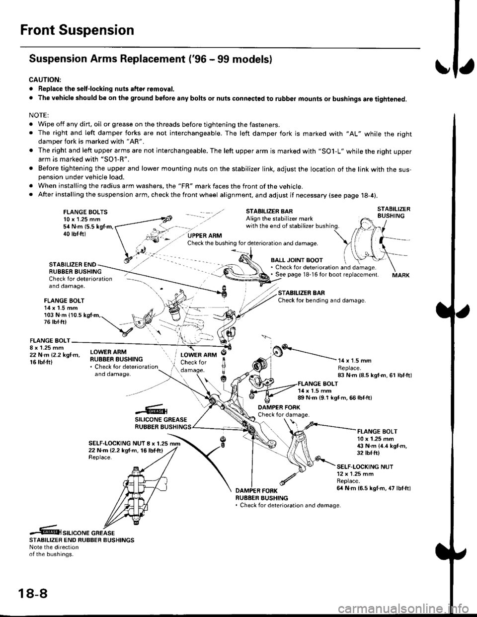
Suspension Arms Replacement ('96 - 99 models)
CAUTION:
. Replace the selt-locking nuts after removal.
. The vehicle should be on the ground betore any bolts or nuts connected to rubber mounts or bushings are tightened.
NOTE:
. Wipe off any dirt, oil or grease on the threads before tightening the fasteners.. The right and left damper forks are not interchangeable. The left damper fork is marked with "AL" while the rightdamper fork is marked with "AR'
. The right and left upper arms are not interchangeable. The left upper arm is marked with "SO1-L" while the right upperarm is marked with "SOl-R".
. Before tightening the upper and lower mounting nuts on the stabilizer link, adjust the location of the link with the sus-pension under vehicle load.
. When installing the radius arm washers, the "FR" mark faces the front ofthe vehicle.. After installing the suspension arm, ch eck the front wheel alignment, and adjust if necessary (see page 18-4).
FLANGE BOLTS10 x 1.25 mm54 N.m 15.5 kgl.m,40 tbf.ftl
STAEILIZER ENDRUBBER BUSHING
BALL JOINT BOOT. Check for deterioration and damage.. See page 18-16 for boot replacement.
STABILIZER BARCheck for bending and damage.
Check for deterioration - ---\--
and damage, -\
FLANGE BOLT14 x 1.5 mm/)l103 N.m {10.5 kg{.m,. t, ,/4,76lb{.ft) t,,"-iV
v:\FLANGE BOLT-
;iffillr-"- ilHitffi*::,"*"
and damaoe,
o.'-----------14 x 1.5 mmReplace.83 N.m {8.5 kgf.m, 61 lbf.ftl
LOWER ARMCheck for
c
JlTTda
1{ x 1.5 mm89 N.m {9.1 kgt m. 66 lbtft)
-6;SILICONE GREASERUBBER BUSHING
DAMPER FORKCheck for damage.
SELF-LOCKING NUT I x 1.2522 N.m (2.2 kg{.m, 16lbf.ftlReplace.
FLANGE BOLT10 x 1.25 mm€ N.m {4.6 kgt m.32 tbf.ft)
SELF-LOCKING NUT12x 1.25 mmReplace.6it N m {6.5 kgf.m, 47 lbf.ftl
RUEBER BUSHING. Check for deterioration and damage.
.6t",.,"o".c"KeSTAAIL|zER END RUBBER EUSHINGSNote the directionof the bushings.
18-8
Page 1133 of 2189
I
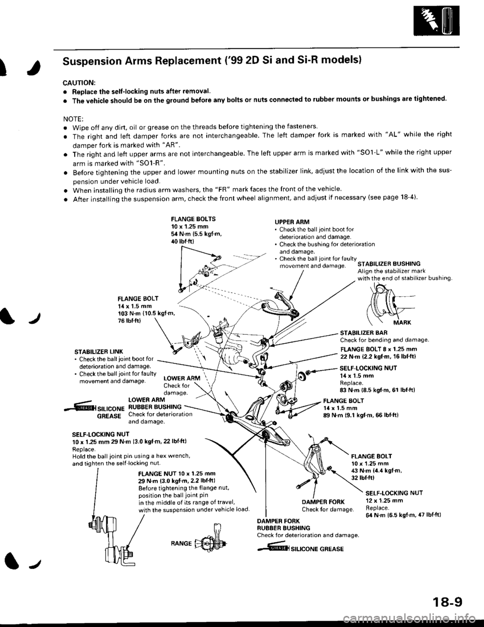
Suspension Arms Replacement ('99 2D Si and Si-R models)
CAUTION:
. Replace the selt-locking nuts after removal.
. The vehicle should be on the ground belore any bolts or nuts connected to rubber mounts or bushings are tightened.
NOTE:
. Wipe off any dirt, oil or grease on the threads before tightening the fasteners
. The right and ieft damper forks are not interchangeable. The left damper fork is marked with "AL" while the right
damper fork is marked with "AR"
. The right and left upper arms are not interchangeable. The left upper arm is marked with "SOl-L" while the right upper
arm is marked with "SO1-R".
. Before tightening the upper and lower mounting nuts on the stabilizer link, adiust the location of the link with the sus-
pension under vehicle load.
. When installing the radius arm washers, the "FR" mark faces the front of the vehicle.
. After installing the suspension arm, check the front wheel alignment, and adjust if necessary (see page 18-4).
FLANGE BOLTS10 x 1.25 mmsit N.m 15.5 kgf.m,40 tbtftl
UPPER ARM' Check the ball joint boot fordeterioration and damage.. Check the bushing for deteriorationano oamage,. Check the ball ioint fo. faultymovement and clamage.STABILIZER BUSHINGAlign the stabilizer markwith the end of stabilizer bushing
FLANGE BOLT14 x 1.5 mm
l./
103 N.m (10.5 kgf.m,76 tbr.ftl
STABILIZER LINK. Check the ballioint bootfordeterioration and damage.. Checkthe ballioint tor faultymovement and damage.
STABILIZER BARCheck for bending and damage.
FLANGE BOLT 8 x 1.25 mm22 N.m (2.2 kgf.m, 16lbf.ft)
SELF-LOCKING NUT14 x 1.5 mmReplace.83 N.m 18.5 kgf m, 61 lbf.ft)
-.6r srr-,co", hSHrtlrT.[*"u
6g619g Check for deteriorationano oamage.
SELF.LOCKING NUT10 x 1.25 mm 29 N m 13.0 kgf m, 22 lbf ftl
Replace.Hold the ball ioint pin using a hex wrench,
and taghten the self'locking nut.
LOWER ARMCheck fordamage.
FLANGE NUT l0 x 1.25 mm
29 N.m 13.0 kgI m,2.2 lbf ft)
Before tightening the {lange nut,position the ball joint Pinin the middle of its range of travel,
with the suspension under vehicle load
FLANGE BOLT14 x 1.5 mm89 N.m 19.1 kgf.m, 66 lbf.ft)
FLANGE BOLT10 x '1.25 mm43 N.m {4.4 kgf.m,32 tbtft)
DAMP€R FORKCheck lor damage.
DAMPER FORKRU88ER BUSHINGCheck for deterioration and damage.
4@lsrlrcoNE GREASE
SELF.LOCKING NUT12 x 1.25 mmReplace.64 N m 16.5 kgl.m, 47 lblft)
J
RANGE
18-9
Page 1141 of 2189
Front Damper
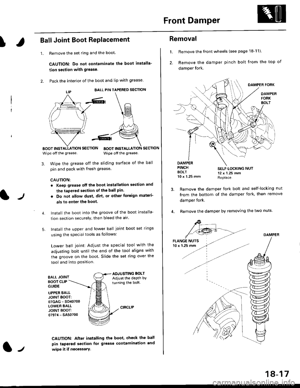
!Ball Joint Boot RePlacement
1.Remove the set ring and the boot.
CAUTION: Do not contaminate the boot installa-
tion section with grease.
Pack the interior of the boot and lip with grease
EALL PIN TAPERED SECTION
EOOT INSTALLATION SECTION
Wipe off the grease.BOOT INSTALLATION SECTION
Wipe off the grease.
lJ
3. Wipe the grease off the sliding surface of the ball
pin and pack with fresh grease.
CAUTION:
. Keep grease off the boot installation section and
the tapeled section of the ball pin.
5.
. Do not allow dust, dirt, or other toreign materi-
als to enter the boot.
Install the boot into the groove of the boot installa-
tion section securely, then bleed the atr.
Install the upper and lower ball joint boot set rings
using the special tools as follows:
Lower ball joint: Adiust the special tool with the
adjusting bolt until the end of the tool aligns with
the groove on the boot. Slide the set ring over the
tool and into Position.
BALL JOINTAOJUSTING BOLTAdjust the depth by
turning the bolt.BOOT CLIPGUIDE
4.
UPPER EALLJOINT EOOT:07GAG - SD40700LOWER BALLJOINT BOOT:07974 - SA50700
CAUTION: After installing the boot, check the ball
pin tapsrod section fol grease contamination and
wipe it if necessary.lt
18-17
Removal
l. Remove the front wheels (see page 18-11).
2, Remove the damper pinch bolt trom the top of
damper fork.
DAMPER FORK
OAMPERFORKBOLT
OAMPERPINCHAOLT10 x 1.25 mm
SELF-LOCKING NUT12 x 1.25 mmReplace.
Remove the damper fork bolt and self-locking nut
from the bottom of the damper fork, then remove
damper fork.
Remove the damper by removing the two nuts
DAMPER
Page 1188 of 2189
Rear Brake Caliper
Reassembly (cont'dl
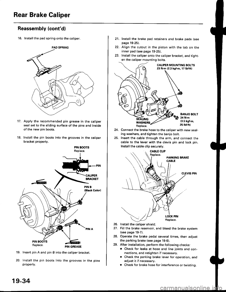
'16. Installthe pad spring onto the caliper.
Apply the recommended pin groase in the caliper
seal set to the sliding surface of the pins and inside
of the new pin boots.
Install the pin boots into the grooves in the caliper
bracket properly.
PIN BOOTSReplsce.
(Bl.ck Colorl
PINRepl6ce.
19. Insert pin A and pin B into the caliper bracket.
20. Install the pin boots into the grooves in thepropefly.
PAD SPRING
11.
PIN GREASE
19-34
pr ns
22.
21. Install the brake pad retainers and brake pads (see
page 19-25).
Align the cutout in the piston with the tab on the
inner pad (see page 19-25).
Install the caliper onto the caliper bracket. and tight-
en the caliper mounting bolts.
CALIPER MOUNTING BOLTS23 N.m {2.3 kg{.m. 17 lbf.ft)
WASHERSReplace.
BANJO BOLT34 N.m13.5 kg{.m.25 rbtft)
24.Connect the brake hose to the caliper with new seal,
ing washers, and tighten the banjo bolt,
Insert ths cable through the arm, and connect the
cabls to the lever with the clevis pin and lock pin.
Install the cable clip securely.
CLEVIS PIN
-t
//t
LOCK PINRoplace.
26. Install the caliDer shield.
27. Fill the brake reservoir, and bleed the brake svstem(see page 19-71.
28. Operate the brake pedal several times, then adjust
the parking brake (see page 19-6).
29. After installation, perform the following checks:. Check for leaks at hose and line joints and con-nections, and retighten if necessary.. Check the parking brake lever for operation, and
adjust it if necessary.
. Check for brake hose for interference or twistinq.
Page 1289 of 2189
Interior Trim
tReplacement
CAUTION:
. Put on gloves to protect your hands.
o When prying with a flat-tip screwdriver, wrap it with protective tape to prevent damage.
NOTE: Take care not to bend or scratch the trim and panels.
4D:
>: Clip locationsa>,2c >,2'lo >,2E >,2
r*'" n t-lt't
\wi, i
' l ll/
_tr* @,
CENTER PILLARUPPER TRIMREAR PILLARTRIM
LOCK CYLINDER TRIM
tl'
I
E'vBELT UPPERANCHOR(see page 20-85)
Disconnect thehigh mount brakelrght connector.
T SIDE TRIMRemove the rear seat cushion and rearseat side bolster lsee page 20-19]'.
)
lnstallation is the reverse of the removal procedure.
NOTE:
. lf necessary, replace any damaged clips.. Before installing the front seat belt upper anchor
and rear shelf. make sure there are no twists or
kinks in the seat belts.(cont'd)
B>,6
REAR SHELF
k"si
fEFT KICKPANEL
20-59
Page 1474 of 2189
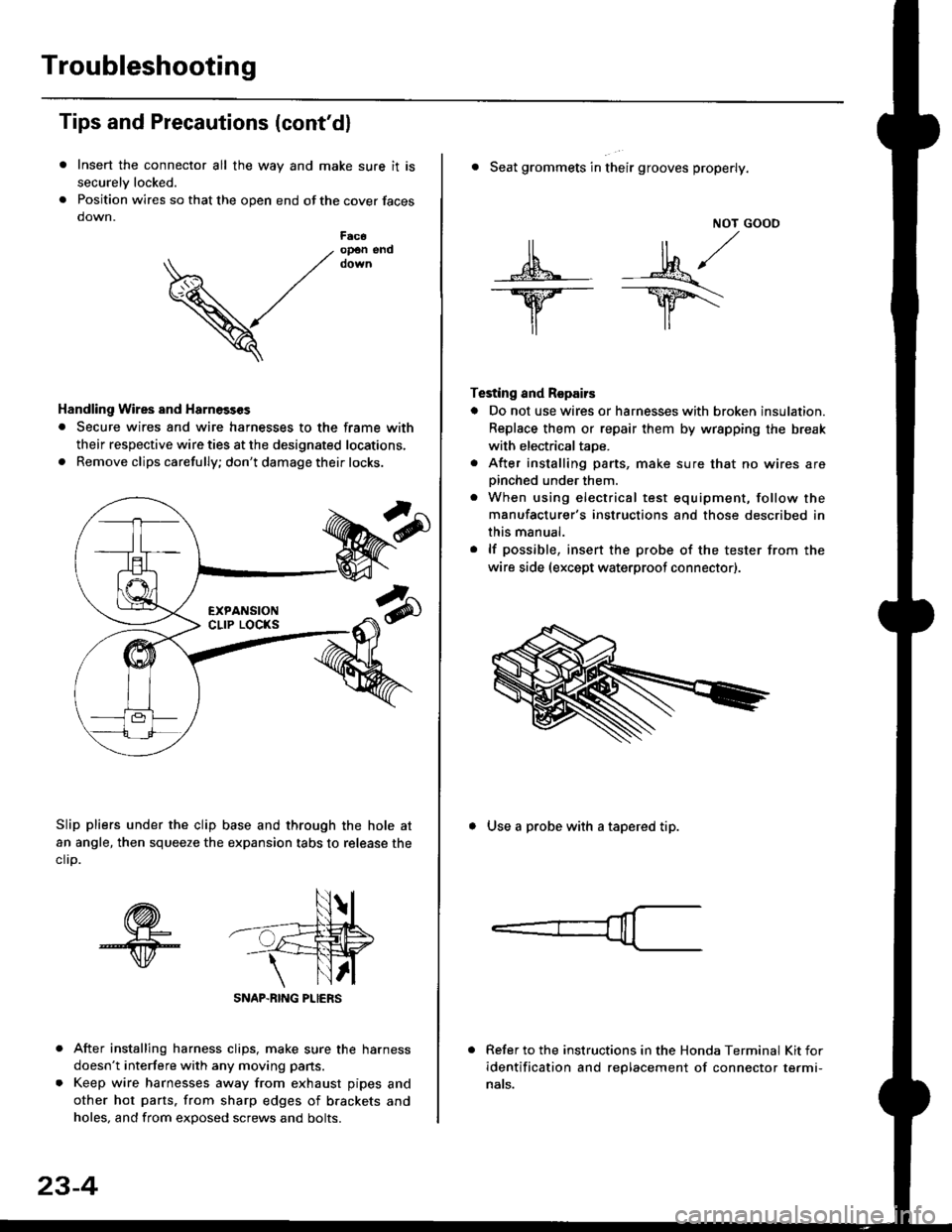
Troubleshooting
Tips and Precautions (cont'dl
Insert the connector all the way and make sure it is
securelv locked.
Position wires so that the open end of the cover faces
down.
After installing harness clips, make sure the harness
doesn't interfere with any moving pans.
Keep wire harnesses away from exhaust pipes and
other hot parts. from sharp edges of brackets and
holes, and from exDosed screws and bolts.
V
F6c6op€n end
Handling Wires and Harnosscs
. Secure wires and wire harnesses to the frame with
their respective wire ties at the designated locations,
. Remove clips carefully; don't damage their locks.
Slip pliers under the clip base and through the hole at
an angle, then squeeze the expansion tabs to release the
clrp.
SNAP-BING PLIERS
23-4
NOT GOOO
ll il,/
s*' -.1}8."/_Y--_Y5\
il ,,
Testing and Repairs
o Do not use wires or harnesses with broken insulation.
Replace them or repair them by wrspping the break
with electricaltaoe.
. After installing parts, make sure that no wires arepinched under them.. When using electrical test equipment, follow the
manufacturer's instructions and those described in
this manual.
. lf possible, insert the probe of the tester from the
wire side (except waterproof connector).
. Seat grommets in their grooves properly.
. Use a probe with a tapered tip.
Refer to the instructions in the Honda Terminal Kit for
identification and replacement of connector termi-
nats.
Page 1479 of 2189
D
INTEGRATEDCONTROL UNITUNDER.OASHFUSE/RELAY BOX
HORN RELAYI Wire colors: WHT/GRttt, WXf/Cnru,l
[GRY, and BLU/RED ,J
POWER WINDOW RELAY
INTERLOCK CONTROL UNIT
'gtP"tat{}r) (}t /t t ------,)
F;;snHn-nnn"nf-H-n o
F !r rr rr rr r,r Lr Ll u u l,r
Fnnnnnnnrrrr-1F rr rr rJ LJ rJ r-r t-r L-r LJ Lr ||J
u_::;_:_:_:_:_l_;I::
*TCM (CVT)
*: Coupe
23-9
Page 1481 of 2189
O
UNDER.OASHFUSE/NELAY BOX
. TCM (CVT): Coupe. KEYLESS DOOR LOCK CONTROL UNIT: '99 model {USAI
REAR WINDOWDEFOGGEB
INTERLOCK CONTROL UNIT
POWER WINDOW RELAY
oF- -=----rr Jl r c
23-11