1996 HONDA CIVIC inter lock
[x] Cancel search: inter lockPage 635 of 2189

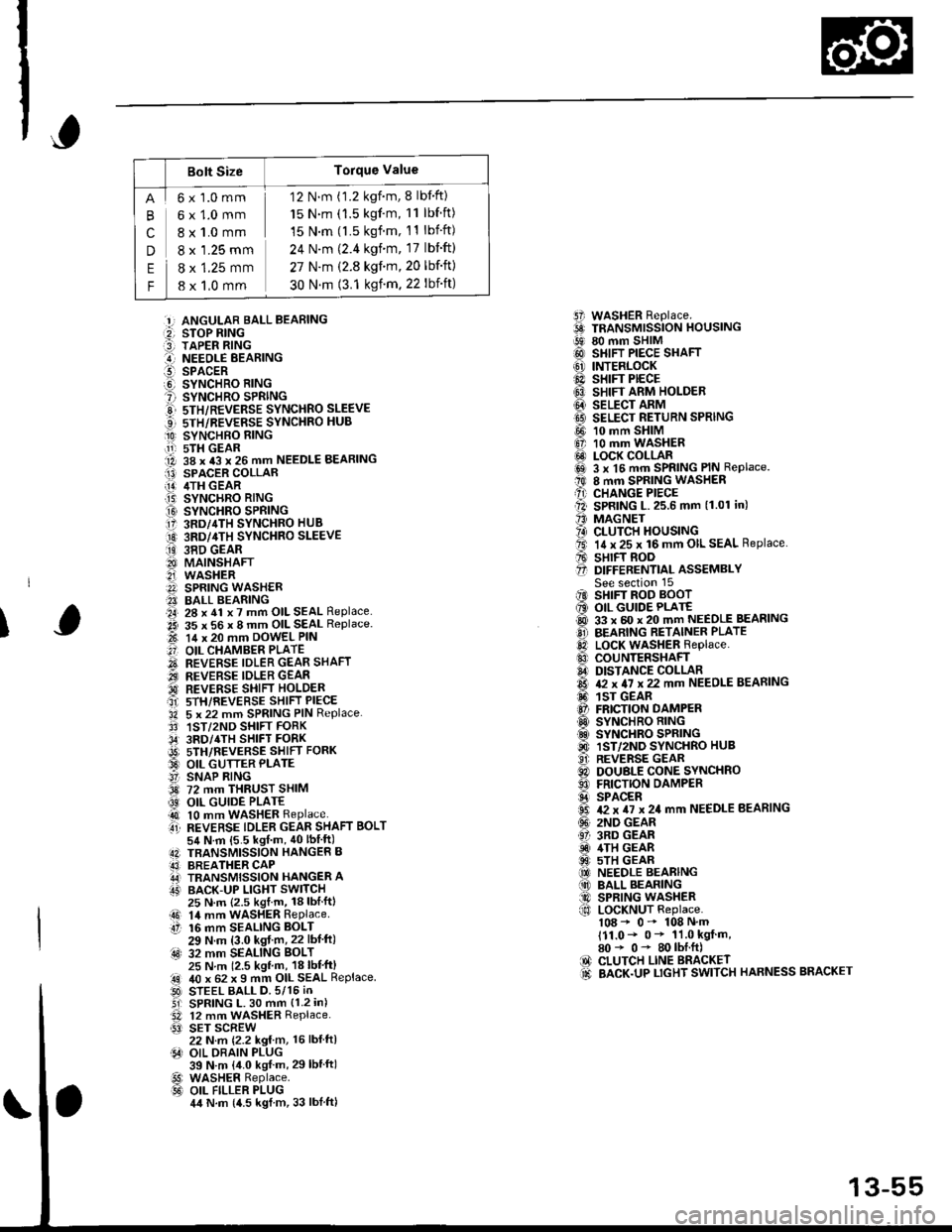
Bolt SizeTorque Value
cn
E
F
6x1.0mm
6x1.0mm
8 x 1.0 mm
8 x '1.25 mm
8 x 1.25 mm
8 x 1,0 mm
12 N.m (1.2 kgnm, 8 lbf'ft)
15 N.m (1.5 kgf'm, 11 lbf ft)
15 N.m (l.5 kgf.m, 11 lbift)
24 N'm (2.4 kgim, 17 lbift)
27 N.m (2.8 kgf.m,20 lbf'ft)
30 N.m (3.1 ksf m. 22 lbift)
5i WASHER Replace.6 TRANSMrssioN HouslNG!9 80 mm SHIM@ SHIFT PIECE SHAFT(6' INTERLOCK@ sHrFr PECE6} SHIFT ARM HOLDER@ seucr nnrvtI9 SELECT RETURN SPRING
@ 10 mm SHIM6, 10 mm WASHER@ LOCK COLLARi6sl 3 x l5 mm SPRING PIN Replace.t0 8 mm SPRING WASHERA) CHANGE PIECEll SPRING L.25.6 mm (1.01 in)'' MAGNET?4) CLUTCH HOUSINGta. 14 x 25 x 16 mm OIL SEAL Replace.A sHrFT BooO D|FFERENT|aL ASSEMBLYSee section 15iIO SHIFT ROD BOOT6 OIL GUIDE PLATE@ 33 x 60 x 20 mm NEEDLE BEASINGO BEARING RETAINER PLATElD LocK WASHER Replace..0 couNTERSHAFIA DISTANCE COLLAR6 & x 4I x 22 mm NEEDLE BEARING6. 1sr GEAR@ FRICTION DAMPERO SYNCHRO RING.d SYNCHRO SPRING@ 1ST/2ND SYNCHRO HUB..9i. REVERSE GEARC) DOUBLE CONE SYNCHROO FRICTION DAMPERS SPACER6 T2 x TI x 24 mm NEEDLE BEARING(!' 2ND GEAR61 3RD GEARiD 4TH GEAR@ 5TH GEAR(O NEEDLE BEARING(10 BALL BEARING@ SPRING WASHERf,o LoCKNUT Replace.108 - 0- 108 N'm111.0- 0* 11.0 kgf m,80* 0- 80lbI.ft)IO CLUTCH LINE BRACKET.d BACK.UP LTGHT SWITCH HARNESS BRACKET
:!, ANGULAR BALL BEABING:2, STOP RING:3] TAPER RING..-I NEEOLE BEARINGl!-- SPACERO SYNCHRO RING? SYNCHRO SPRINGE 5TH/REVERSE SYNCHRO SLEEVE...] sTH/REVERSE SYNCHRO HUB
O SYNCHBO EING.11-r sTH GEAR1A 38 x 43 x 26 mm NEEDLE BEARINGI13) SPACER COLLAR[!] /ITH GEAR.T5) SYNCHRO RING
O SYNCHRO SPRING17 3RD/4TH SYNCHRO HUB
O 3RD/4TH sYNcHRo SLEEVE
ii9 38D GEAR8I MAINSHAFT2i WASHERA SPRING WASH€R?I BALL BEARING.a4, 28 x 41 x 7 mm OIL SEAL Replace..2i 35 x 56 x 8 mm OIL SEAL Replace.t-t 14 x 20 mm DowEL PIN
.'] OIL CHAMBER PLATE
O REVERSE IDLER GEAR SHAFT.iI.., REVERSE IDLER GEAR'd REVERSE SHIFI HOLDERait srH/REVERSE sHIFT PIECE'34 5 x 22 mm SPRING PIN Replace.3' 1ST/2ND SHIFT FORK,34' 3RD/4TH SHIFT FORKi9t) srH/nevense sstrr ronx33 OIL GUTTER PLATE!' SNAP RING3d 72 mm THRUST SHIM
@ OIL GUIDE PLATE4t 10 mm WASHER Replaceti REVERSE TDLER GEAR SHAFT BoLT54 N.m {5.5 kgf m, 40lbIft)4N TBANSMISSION HANGER B43] BREATHER CAPA,J TRANSMISSION HANGER AIT' BACK-UP LIGHT SWITCH
I
25 N.m {2.5 kgl.m, 18lblftl14 mm WASHER RePlaceaO 14 mmtt 16 mm16 mm SEALING BOLT29 N.m (3.0 kgf m,22 lbf ft):4s) 32 mm SEALING BoLT25 N m 12.5 kgl m, 18 lbl'ft)40 x 62 x I mm OIL SEAL ReplaceSTEEL BALL D.5/15 iNSPRING L. 30 mm {1.2 in)12 mm WASHER Replace.SET SCREW22 N.m {2.2 kg{ m, 16 lbl ftlOIL DRAIN PLUG39 N.m {4.0 kgf m, 29lbtftlWASHER Replace.OIL FILLER PLUG4,t N.m {4.5 kgl m, 33 lblftl
.!rl00
@l
13-55
Page 639 of 2189

Change Holder AssemblY
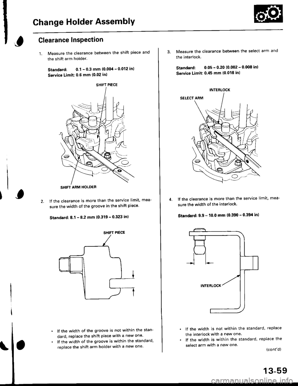
,Glearance InsPection
1.Measure the clearance between the shift piece and
the shift arm holder.
Standard: 0.1 - 0.3 mm {0.004 - 0.012 in)
service Limit: 0.6 mm {0.02 in)
lf the clearance is more than the service limit, mea-
sure the width of the groove in the shift piece'
Standard: 8.1 - 8 2 mm {0'319 - 0.323 in}
lf the width of the groove is not within the stan-
dard, replace the shift piece with a new one'
lf the width of the groove is within the standard,
replace the shift arm holder with a new one'
SHIFT PIECE
SHIFT ARM HOLDER
SHIFT PIECE
4.
3. Measure the clearance between the select arm and
the interlock.
Standard: 0.05 - 0.20 10 002 - 0.008 inl
Service Limit:0.45 mm (0.018 inl
lf the clearance is more than the service limit, mea-
sure the width of the interlock.
Standatd: 9.9 - 10.0 mm (0.390 - 0.39't in)
lf the width is not within the standard, replace
the interlock with a new one.
lf the width is within the standard, replace the
select arm with a new one.(cont'd)
INTERLOCK
13-59
Page 641 of 2189

UO
11. Measure the clearance between the select arm and
the change Piece.
Standard: 0.05 - O'25 mm 10'002 - 0'010 in)
Servica Limii: 0.5 mm {0.02 in)
lf the clearance is more than the service limit, mea-
sure the width of the change Plece.
Standard: 12.05 - 12.15 mm {0.47'|{ - 0 47tI| inl
CHANGE PIECE
lf the width is not within the standard, replace
the change Piece with a new one'
lf the width is within the standard, replace the
select arm with a new one.
't2.
a
a
SELECT ARM
Removal
1. Bemove the shift piece shaft. then remove the shift
piece and the interlock.
SHIFT PIECE SHAFT
INTERLOCK
2. Remove the change holder assembly'
13-61
Page 671 of 2189

Transmission
ReassemblY
1. Install the new oil seal
2. Set the change Piece.
3. Install the shift rod
4. Install the steel ball' the spring, and the set screw'
5. Install the spring washer and change piece attach-
ing bolt.
6. Install the shift rod boots.
8x1.0mm31 N.m 13.1 kg-m,22lb-ltl
CHANGEPIECE
@:4OIL SEALReplace.SPRINGWASHER
7. Install the oil chamber Plate'
6 x '1.0 mm12 N.m (1.2 kg-m,9lb-ft|
SPRING
, /L.256fim B()(
@ / t't o'ti"l I
{zw"y-6@
q
10.
Set the spring washer and the washer'
lnstall the mainshaft, the countershaft, and the shift
fork assemblies.
NOTE: Align the finger of the interlock with the
groove in the shift fork shaft.
SHIFT FORKS
13-91
Page 672 of 2189

Transmission
Reassembly (cont'd)
11. Installthe change holder assembly.
6x1.0mm15 N.m {1.5 kgf.m,
12 N.m {1.2 kgf.m,9lbtftlCHANGE HOLDERASSEMBLY
Install the shift piece and the interlock. then installthe shift piece shaft.
12.
13-92
(
13. Measure the distance @ after mounting the shiftpiece shaft. lf it's incorrect. check the installation.
Distance @: 11.9 - 12.3 mm {0./t7 - 0.48 inl
14. Install the .everse idler gear and the reverse idlergear shaft.
REVERSE IDLER GEAR
REVERSEIDLE
Page 681 of 2189

Description
The automatic transmission is a 3-element torque converter and a dual-shaft electronically controlled unit which provides
4 soeeds forward and 1 reverse.
Torque Convertel, Geats, and Clutches
The torque converter consists of a pump, turbine and stator, assembled in a single unit. They are connected to the engine
crankshaft so they turn together as a unit as the engine turns. Around the outside of the torque converter is a ring gear
which meshes with the starter pinion when the engine is being started. The entire torque converter assembly seryes as a
flywheel while transmiuing power to the transmission mainshaft.
The transmission has two parallel shafts: the mainshaft and the countershaft. The mainshaft is in Iine with the engine
crankshaft. The mainshaft includes the 1st, 2nd and 4th clutches, gears tor 2nd, 4th, reverse and lst (3rd gear is integral
with the mainshaft, while the reverse gear is integral with the 4th gear). The countershaft includes the 3rd clutch, and
gears for 3rd,2nd, 4th, reverse. 1st and park. The gears on the mainshaft are in constant mesh with those on the counter-
shaft. When certain combinations of gears in transmission are engaged by clutches. power is transmitted from the main-
shaft to the countershaft to provide E, ld, E, and E positions.
Electronic Control
The electronic control svstem consists of the Powertrain Control Module {PCM), sensors, a linear solenoid and four
solenojd valves. Shifting and lock-up are electronically controlled for comtonable driving under all conditions. The PCM is
located below the dashboard, under the front lower panel on the passenger's side
Hydraulic Control
The valve bodies include the main vatve body, the secondary valve body, the regulator valve body, the servo body and the
lock-up valve body through the respective separator plates, They are bolted on the torque converter housang
The main valve body contains the manual valve, the 1-2 shift valve. the 2nd orifice control valve, the CPB {Clutch Pressure
Back-up) valve, the modulator valve. the servo control valve, the relief valve, and ATF pump gears The secondary valve
body contains the 2-3 shift valve. the 3-4 shift valve, the 3-4 orifice control valve, the 4th exhaust valve and the CPC (Clutch
pressure Control) valve. The regulator valve body contains the pressure regulator valve, the torque converter check valve,
the cooler relief valve, and the lock-up control valve. The servo body contains the servo valve which is integrated with the
reverse shift fork, and the accumulators. The lock-up valve body contains the lock-up shift valve and the lock-up timing
valve. The linear solenoid and the shift control solenoid valve Ay'B are bolted on the outside of the transmission housing,
and the lock-up control solenoid valve Ay'B is bolted on the outside of the torque converter housing. Fluid from regulator
passes through the manual valve to the various control valves. The clutches receive fluid from their respective teed pipes
or internal hydraulic circuit.
Shift Control Mechanism
Input from various sensors located throughout the car determines which shift control solenoid valve the PCM will activate
Activating a shift control solenoid valve changes modulator pressure, causing a shift valve to move. This pressurizes a line
to one of the clutches, engaging that clutch and its corresponding gear, The shift control solenoid valves A and B are con-
trolled by the PCM.
Lock-up Mechanism
In ,Dt1 position, in 3rd and 4th. and in E position in 3rd, pressurized fluid is drained from the back of the torque converter
through a fluid passage, causing the lock-up piston to be held against the torque converter cover. As this takes place, the
mainshaft rotates at the same as the engine crankshaft. Together with hydraulic control, the PCM optimizes the timing of
the lock-up mechanism. The lock-up valves control the range of lock-up according to lock-up control solenoid valves A and
B, and linear solenoid. When lock-up control solenoid valves A and B activate, the modulator pressure changes The lock-
up control solenoid valves A and B and the linear solenoid are controlled by the PCM.
(cont'd)
14-3
Page 682 of 2189

Description
(cont'dl
Gear Selection
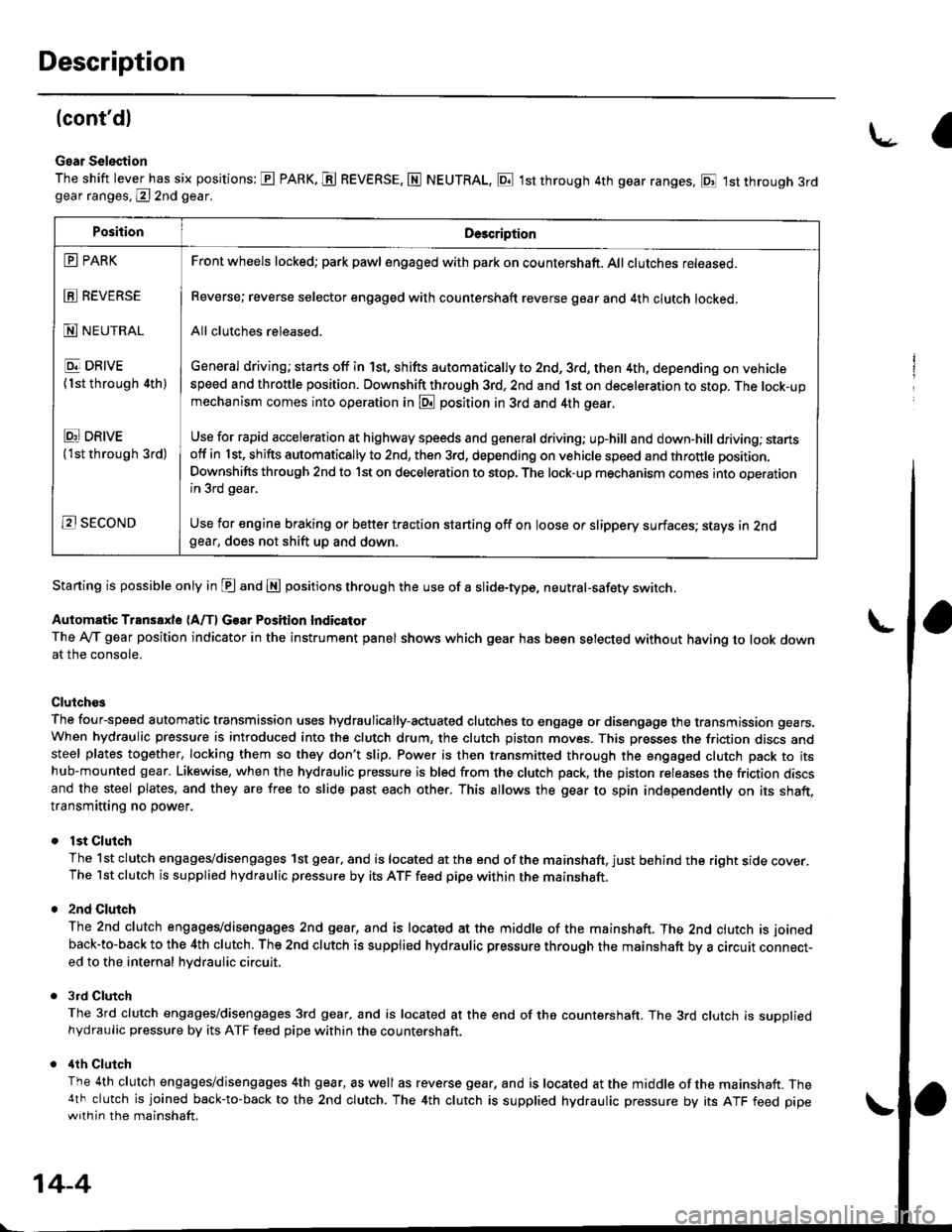
The shift lever has six positions: E PARK. E REVERSE, N NEUTRAL, E 1st through 4th gear ranges, E 1st through 3rdgear ranges, @ 2nd gear.
Starting is possible only in E and E positions through the use of a slide-type, neutral-safety switch.
Automatic Transaxle (A/f, Gear Position Indicator
The Ay'T gear position indicator in the instrument panel shows which gear has been selected without having to look downat the console.
Clutch€s
The four-speed automatic transmission uses hydraulically-actuated clutches to engage or disengage the transmission gears.When hydraulic pressure is introduced into the clutch drum, the clutch piston moves. This presses the friction discs andsteel plates together, locking them so they don't slip. Power is then transmitted through the engaged clutch pack to itshub-mounted gear. Likewise, when the hydraulic pressure is bled from the clutch pack, the piston releases the friction discsand the steel plates, and they are free to slide past each other. This allows the gear to spin independently on its shaft,transmitting no power.
lst Clutch
The 1st clutch engages/disengages 1st gear, and is located at the end of the mainshaft, just behind the right sroe cover.The 1st clutch is supplied hydraulic pressure by its ATF feed pipe within the mainshaft.
2nd Clulch
The 2nd clutch engagegdisengages 2nd gear, and is located at the middle of the mainshaft. The 2nd clutch is joined
back-to-back to the 4th clutch. The 2nd clutch is supplied hydraulic pressure through the mainshaft by a circutr connect-ed to the internal hvdraulic circuit,
3rd Clutch
The 3rd clutch engages/disengages 3rd gear, and is located at the end of the countershaft. The 3rd clutch is suooliedhydraulic pressure by its ATF feed pipe within the countershaft.
ilth Clutch
The 4th clutch engages/disengages 4th gear, as well as reverse gear, and is located at the middle of the mainshaft. The4th clutch is joined back-to-back to the 2nd clutch. The 4th clutch is supplied hydraulic pressure by its ATF feed pipewith in the mainshaft.
\-a
PositionDe3cription
E PARK
E REVERSE
N NEUTRAL
E DRIVE
{1st through 4th)
Ei DRtvE('lst through 3rd)
B SECOND
Front wheels locked; park pawl engaged with pa* on countershaft. All clutches released.
Reverse; reverse selector engaged with countershaft reverse gear and 4th clutch locked.
All clutches released.
General driving; starts off in 1st, shifts automatically to 2nd, 3rd, then 4th, depending on vehiclespeed and throttle position. Downshift through 3rd, 2nd and 1st on deceleration to stop. The lock-upmechanism comes into operation in @ position in 3rd and 4th gear.
Use for rapid acceleration at highway speeds and general driving; up-hill and down,hill dfiving; stansotf in 1st, shifts automatically to 2nd, then 3rd, depending on vehicle speed and throttle position.
Downshifts through 2nd to lst on deceleration to stop. The lock-up mechanism comes into operationin 3rd gear,
Use for engine braking or better traction starting off on loose or slippery surfaces; stays in 2ndgear, does not shift up and down.
14-4
Page 685 of 2189

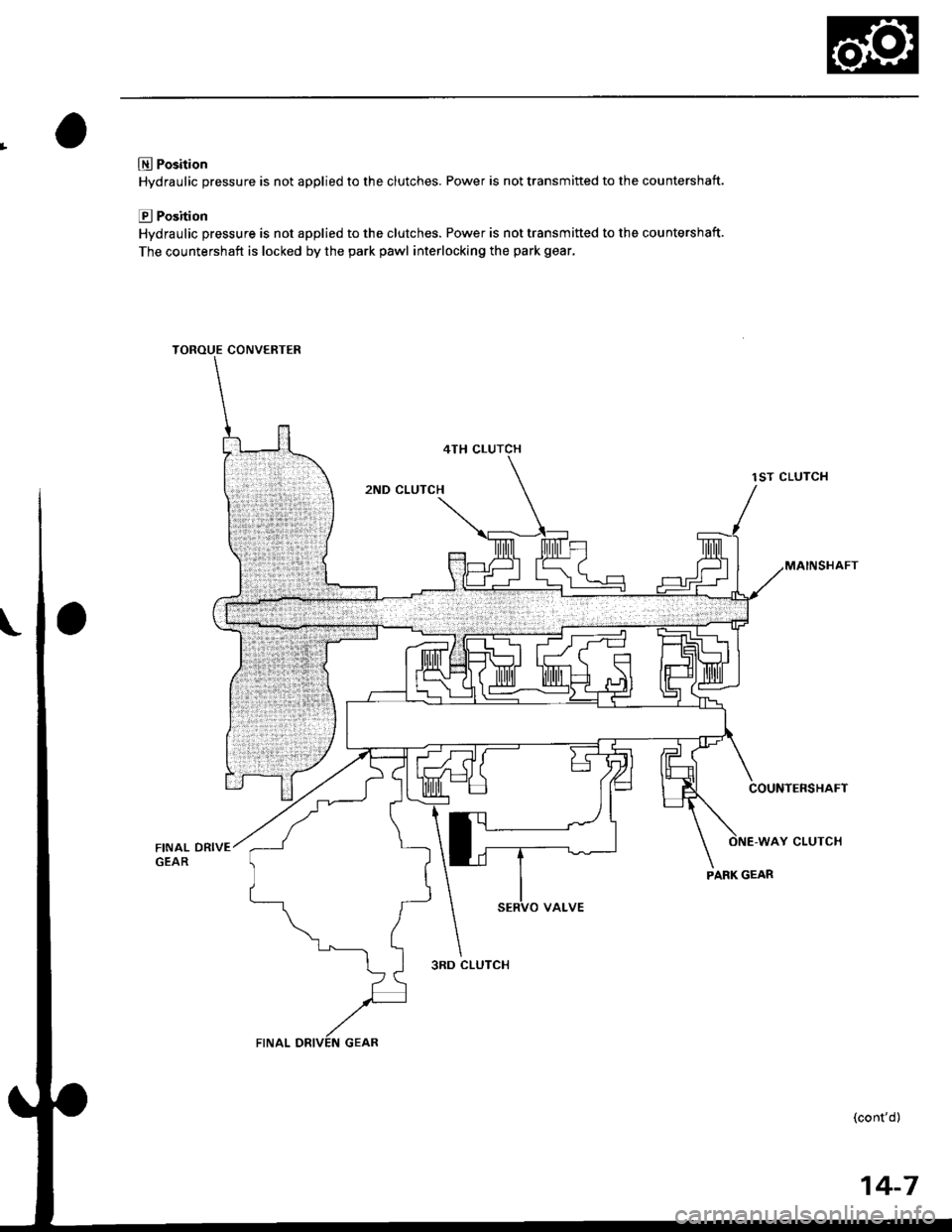
lXl Position
Hydraulic pressure is not applied to the clutches. Power is not transmifted to the countershaft.
E Position
Hydraulic pressure is not applied to the clutches. Power is not transmitted to the countershaft.
The countershaft is locked by the park pawl interlocking the park gear.
TOROUE CONVERTER
rST CLUTCH
COUNTERSHAFT
FINAL DRIVE
3RD CLUTCH
14-7