Page 452 of 2189

\Crankshaft Speed Fluctuation (GKFI Sensor .
firC- 48 Models, '99 - 00 D16Y5 engine with M/Tl
The scan tool indicates Diagnostic Trouble Code (DTC) P1336; Intermiftent interruption in the Crankshaft Speed
Fluctuation (CKF) sensor circuit.
ThescantooIindicatesDiagnosticTroub|ecode{DTC)P1337:NosignaIinthecrankshaftspeedF|uctuation(cKF}
sensor circuit.
D6scription
Thediagnosticsystemhasapu|serrotoronthecrankshaftandapu|sepick-upsensorontheengineblock.TheEcM/PcM
monitors the crankshaft speed ftuctuation based on the cKF sensor signal, and judges that 8n engine misfire occurred if
the fluctuation goes beyond a predetermined limit'
I
fPrk6l
lFr3g7-l
CKF SENSOR 3P CONNECTOR
L:l.)l l.' -Ir-T--T---.]l1 l2l3llL-''---r
CKFM I I CKFP
twrfit 1,.^ | lsLul\.7
Terminal side of male terminals
CKF MIWHT}
CKF PIBLUI
I(cont'd)
- The MtL hds been reported on.- DTC P1336 and/or P1337 a.e
stored.
P.oblem v€rific.tion:1. Do the ECM/PCM Reset Proce-
dure.2. Stan the enginelntormittont lailur6, tY3tom b OK
at thit tima. Chock tor Poor con'
nactions or loota wito! at C102
IC-KF son$rl .nd ECt /PCM, and
mrka suro CKF tonaor mounting
boh ittigM.
Chock for .n open in tho CKF aen-
30t:1. Turn the ignition switch OFF
2. Disconnect the CKF sensor 3P
connector,3. Measure the resista nce
between the CKF sensor 3P
connector terminals No. 1 and
No.3.
ls there 1.6- 3.2 kO?
Ch€ck tor a short in the CKF son'
30tiCheck {or continuitY between
body ground and the CKF sensor
3P connector termin6ls No. 1 and
No.3 individuallY.
(To page 11 184)
1 1-183
Page 570 of 2189
lllustrated Index
\
NOTE:
. Whenever the transmission is removed, clean and grease the release bearing sliding surface
. lf the parts marked with an asterisk (*) are removed, the clutch hydraulic system mustbe bled (seepage 12-6)
. Inspect the hoses for damage, leaks, interference, and twisting
'RESERVOIF TANK
ASSIST SPRING
LOCK PIN
5x1,0mm9.8 N.m (1.0 kgf.m,7.2 tbtftl*CLUTCH LINE15 N.m {1.5 kgJ m,11 tbt.ft)
RELEASE BEARINGRemoval/lnspection, page 12-1 1Installation, page 12-'12
*CLUTCH MASTER CYLINDERRemoval/lnstallation, page 12 5
6x1.0mm9.8 N.m (1.0 kgf.m,7.2 tbf.ft)
FLYWHEELInspectaon, page 12IReplacement, Page 12-9
CLUTCH DISCRemoval/lnspection, page 1 2-8
lnstallation, page 12-'10
'12 x 1.0 mm118 N.m {12.0 kgt'm,86.8lbfft)
PBESSURE PLATEBemoval/lnspection, page 12 7Installation, page 12''10
8 x 1.25 mm22 N m (2.2 kgf.m, 16lbf ft)
ISLAVE CYLINDERRemoval/lnstallation, page 12_6
12-3
Page 571 of 2189

Glutch Pedal
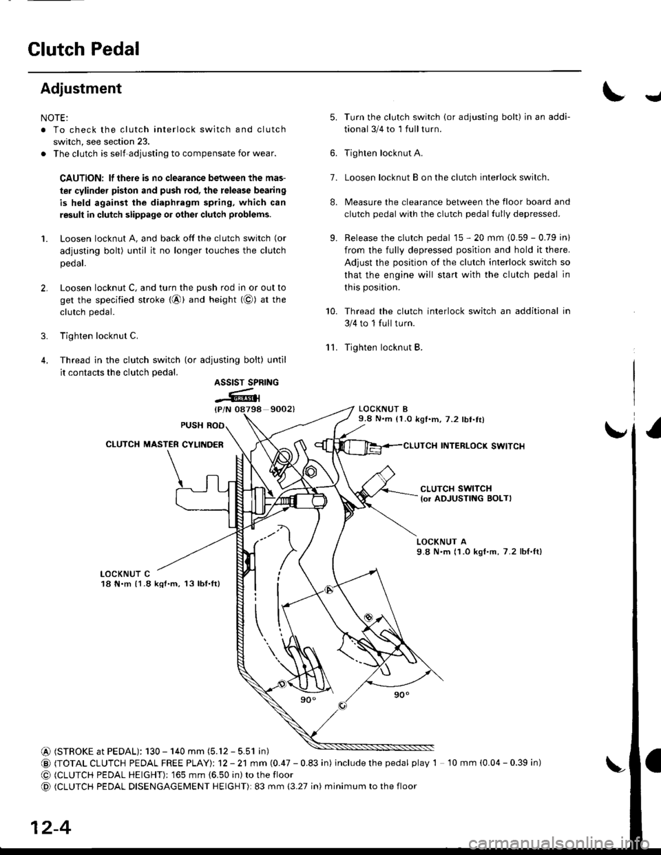
Adjustment
NOTE:
. To check the clutch interlock switch and clutch
switch, see section 23.
. The clutch is self-adjusting to compensate for wear.
CAUTION: lf there is no clearance between the mas-
ter cylinder pislon and push rod, the release bearing
is held against the diaphragm spring, which can
result in clutch slippage 01 other clutch problems.
1. Loosen locknut A, and back off the clutch switch (or
adjusting bolt) until it no longer touches the clutch
peoar.
2. Loosen locknut C, and turn the push rod in or out to
get the specified stroke {@} and height (@) at tne
clutch pedal.
3. Tighten locknut C.
4. Thread in the clutch switch {or adiusting bolt) until
it contacts the clutch pedal.
9002)
Turn the clutch switch (or adjusting bolt) in an addi-
tional 3/4 to 1 full turn.
Tighten locknut A.
Loosen locknut B on the clutch interlock switch.
Measure the clearance between the floor board and
clutch pedal with the clutch pedal fully depressed.
Release the clutch pedal 15 - 20 mm {0.59 - 0.79 in)
from the fully depressed position and hold it there.
Adjust the position of the clutch interlock switch so
that the engine will start with the clutch pedal in
this position.
Thread the clutch interlock switch an additional in
3/4 to 1 full turn.
Tighten locknut B.
LOCKNUT B9.8 N.m (1.0 k91.m,7.2 lbt.tt)
INTERLOCK SWITCI{
J
'lL
5.
7.
8.
9.
10.
ASSIST SPRING
-Atl
CLUTCH SWITCH
lo. ADJUSTING BOLTI
LOCKNUT A9.8 N'm (1.0 kgI.m, 7.2 lbf,ft)
LOCKNUT C18 N.m {1.8 kql.m, 13lbf.ft}
@ (STROKE at PEDAL): 130 - 140 mm (5.12 - 5.51 in)
@ (TOTAL CLUTCH PEDAL FREE PTAYI: 12 - 21 mm (0.47 - 0.83 in) includethepedal play 1 10 mm (0.04 - 0.39 in)
@ (CLUTCH PEDAL HEIGHT): '�]65 mm {6.50 in) to the floor
@ (CLUTCH PEDAL DISENGAGEMENT HEIGHT): 83 mm (3.27 in) minimum to the floor
12-4
Page 591 of 2189

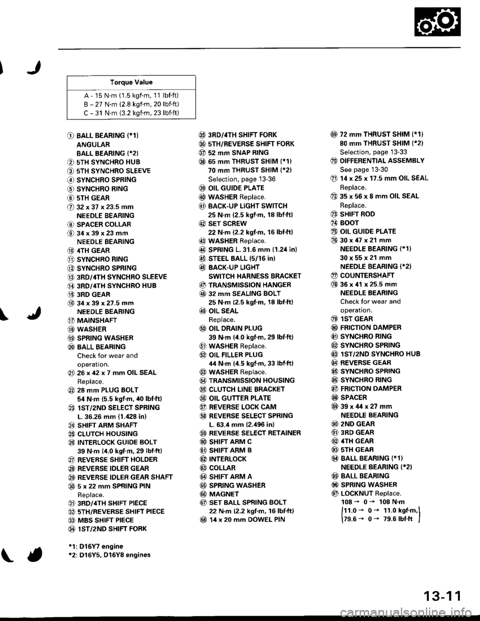
Torque Value
A - 15 N.m (1.5 kgf.m, 1'1 lbf.ft)
B - 27 N.m (2.8 kgf.m. 20 lbift)
C - 31 N.m {3.2 kgnm, 23 lbift)
\
O BALL BEARING (*T)
ANGULAR
BALL BEARING {*2I
O 5TH SYNCHRO HUB
O 5TH SYNCHRO SLEEVE
€) SYNCHRO SPRING
o SYNCHRO B|NG
@ 5TH GEAR
@ gz xgt x 23.5 mm
NEEDLE BEARING
@ SPACER COLLAR
@34x39x23mm
NEEDLE BEARING
(D 4TH GEAR
O SYNCHRO RING
C) SYNCHRO SPRING
CO 3RD/4TH SYNCHRO SLEEVE
@ 3RD/4TH SYNCHRO HUB
(} 3RD GEAR
@34x39x27.5mmNEEDLE BEARING
G) MAINSHAFT
G) WASHER
@ SPRING WASHER
@ BALL BEARING
Check for wear and
operation.(E 26x42x7 mm OIL SEAL
Replace.
@ 28 mm PLUG BOLT
5,1 N.m {5.5 kgf'm, /t0 lbt'ft)
@ lsT/zND SELECT SPRING
L. 36.26 mm (1./P8 in)
@ SHIFT ARM SHAFT
@ CLUTCH HOUSING
@ INTEELOCK GUIDE BOLT
39 N.m (4.0 kgf.m, 29 lbf.ftl
@ REVERSE SHIFT HOLDER
@ REVERSE IDLER GEAR
@ REVERSE IDLER GEAR SHAFT
@ 5 x 22 mm SPRING PIN
Replace.
@ 3RD/4TH SHIFT PIECE
@ 5TH/REVERSE SHIFT PIECE
@ MBS SHIFT PIECE
@ 1ST/2ND SHIFI FORK
*1:D16Y7 engine*2: D16Y5, D16Y8 engines
@ 3RD//|TH SHIFT FORK
@ 5TH/REVERSE SHIFT FORK
@ 52 mm SNAP RING
@ 65 mm THRUST SHIM (*11
70 mm THRUST SHIM (*21
Selection, page 13-36
@ OIL GUIDE PLATE
@ wASHER Replace.
@ BACK.UP LIGHT SWITCH
25 N.m (2.5 kgf'm, 18 lbf'ft)
@ sET SCREW
22 N.m {2.2 kgf.m, 16 lbl.ft}
@ WASHER Replace.
@D SPRING 1.31.6 mm (1.2,1inl
@ STEEL BALL 15/16 in)
@ BACK-UP LIGHT
SWITCH HARNESS BRACKET
@ TRANSMISSION HANGER
@ 32 MM SEALING BOLT
25 N.m (2.5 kgf.m, 18 lbt'ft)
@ OIL SEAL
Replace.
@ OIL DRAIN PLUG
39 N.m (4.0 kgf.m, 29 lbf.ft)
@ WASHER Replace.
@} OIL FILLER PLUG
44 N.m (4.5 kgf.m, 33 lbf'ftl
@ WASHER Replace.
@) TRANSMISSION HOUSING
€) CLUTCH LINE BRACKET
@ OIL GUTTER PLATE
@ REVERSE LOCK CAM
@ REVEBSE SELECT SPRING
L. 63.4 mm {2.,196 in)
@ REVERSE SELECT RETAINER
@ SHIFT ARM C
@ SHIFT ARM B
@ INTERLoCK
@ COLLAR
@ SHIFT ARM A
@ SPRING WASHER
@ MAGNET
@ sET BALL SPRING BOLT
22 N.m (2.2 kgf.m, 16 lbf.ftl
@ 14 x 20 mm DOWEL PIN
@ 72 mm THRUST SHIM l*11
80 mm THRUST SHIM (*21
Selection, page '13-33
@ DIFFERENTIAL ASSEMBLY
See page 13-30
@ 14 x 25 x 17.5 mm OIL SEAL
Replace.
@ 35 x 56 x 8 mm OIL SEAL
Replace.
@ SHIFT ROD
@ BOOr
@ OIL GUIDE PLATE
@30x47x21 mm
NEEDLE BEARING (* 1}
30x55x21 mm
NEEDLE BEARING {'2)
@ COUNTERSHAFT
@36x41 x 25.5 mm
NEEDLE BEARING
Check for wear and
operatron.
@ lsT GEAR
@ FRICTION DAMPER
@ SYNCHRO RING
@ SYNCHRO SPRTNG
@ lST/2ND SYNCHRO HUB
@ REVERSE GEAR
@ SYNCHRO SPRING
@ SYNCHRO RING
@ FRICTION DAMPER
@ SPACER
@39x4lx27mm
NEEDLE BEARING
@ 2ND GEAR
@ 3RD GEAR
@ 4TH GEAR
@ sTH GEAR
@) BALL BEARING {* 1}
NEEDLE BEARING (*2}
@ BALL BEARING
@) SPRING WASHER
@ LoCKNUT Replace.
108 - 0- 108 N.m
ftt.o* o- 1r.o kst.m,l
179.6- 0- 79.6 rbtft I
13-1 1
Page 594 of 2189
Reverse ldler Gear
Mainshaft, Cou ntershaft,
Shift Fork
Removal
1. Remove the reverse shift holder.
REVERSE SHIFTHOLOER
Remove the reverse id ler
idler gear.
gear shaft and reverse
REVERSE IDLERGEAR SHAFT
13-14
Disassembly
1. Remove the interlock guide bolt from under the
clutch housing.
SHIFT ARM 8ATTACHING BOLT
CLUTCHHOUSING
INTERLOCK GUIDE BOLT
Remove the shift arm B attaching bolt.
Remove the mainshaft and countershaft assemblies
with the shift fork from the clutch housinq.
NOTE: Before removing the mainshaft and counter-
shaft assemblies, tape the mainshaft splines to pro-
tect the seal.
Tape the mainshaftsplines.
WASHER
SPRINGWASHER
Page 609 of 2189

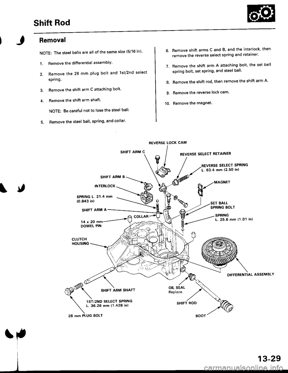
Shift Rod
Removal
NOTE: The steel batlsareall of the same size (5/16 in)'
1. Remove the differential assembly'
2. Remove the 28 mm plug bolt and lst/2nd select
spring.
3. Remove the shift arm C attaching bolt'
4. Remove the shift arm shaft'
NOTE: Be careful notto lose the steel ball'
5. Remove the steel ball, spring, and collar'
SHIFT ARM C
SHIFT ARM B
INTERLOCK
6. Remove shift arms C and B, and the interlock, then
remove the reverse select spring and retainer'
7. Remove the shift arm A attaching bolt, the set ball
spring bolt, set spring, and steel ball'
8. Remove the shift rod' then remove the shift arm A'
9. Remove the reverse lock cam'
10. Remove the magnet.
CAM
REVERSE SELECT RETAINER
REVERSE SELECT SPRING
L. 63.4 mm {2.50 inl
REVERSE LOCK
lIV/
' lJ
\s
SPRING L. 21.4 mm(0.843 in)
SI{IFT ARM A
14x20OOWEL PIN
COLLAR
,*(S* \
6S* srtrr ran,t srarr
\
',)r,r"o r..."r "rr,*n
t. 36.26 mm {1.428 in,
28 mm PI-UG BOLT
OIL SEALReplace.
&-"onn"
BALLSPRING EOLT
SPRINGL. 25.6 mm 11.01 inl
DIFFERENTIAL ASSEMBLY
SHIFT ROD
Page 619 of 2189

Transmission
Reassembly
NOTE: The steel balls are all ofthe same size (5/16 in).
1. Install the magnet and reverse lock cam.
2. Set shift arm A on the clutch housing, then install
the shift rod.
3. Install the spring washer and shift arm A attaching
bolt.
Installthe steel ball, spring, and set ball spring bolt.
Install shift arm B in the interlock, then set it on the
clutch housing.
1.
Insert shift arm shaft in the clutch housing.
Install the collar, spring. and steel ball into the case.
Compress the ball and insert the shift arm shaft,
Install shift arm C in shift arm A, then insert the shift
arm shaft.
Install the reverse select retainer and reverse select
spring onto shift arm shaft.
Install the differential assembly.
5.
8.
9.
10.
A:8x1.0mm3'l N,m (3.2 kgt.m,23 lbf.ft)
6 x 1.0 mm15 N.m 11.5 kgt.m, 11 lbt'ftl
OIL SEALReplace.
SI{IFT ARM C
COLLAR
REVERSE SELECT SPRINGL. 63.4 mm 12.50 in)
REVERSE LOCK CAM
REVERSE SELECT RETAINER
sHtFT ARM ' ___\.*^
rNrERLocK p
|Jiiill---=l@
MAGNET
SET BALL SPRING BOLT22 N.m 12.2 kgl.m, 16 lbf'ftl
SPRINGL. 25.6 mm (1.O1 in)
SHIFT AFM A
CLUTCHHOUSING
SHIFT ARM SHAFT
(cont'd)
13-39
SHIFT ROD
l
BOOT
Page 620 of 2189
Transmission
Reassembly lcont'dl
11. Position the 36 mm spring washer and washer onto
the mainshaft bearing.
MAINSHAFT/COUNTERSHAFTSHIFT FORK ASSEMELIES
Tape the mainshaftsplines.
12.
13.
Install the mainshaft, countershaft, and shift fork
assemblies.
NOTE; Align the finger of the interlock with thegroove in the shift fork shaft,
lnstall the spring washer and shift arm B attaching
bolt.I x 1.0 mm31 N.m (3.2 kgl.m, 23 lbt.ft)
IST/2ND SELECT SPRINGL. 36.26 mm 11.428 in)
54 N.m 15.5 kgf.m,40 tbt.ftl
SPf,INGWASHER
GUIDE BOLT
14.
39 N.m 14.0 kgf.m, 29 lbf.frl
Install the 1sv2nd select spring, 28 mm plug bolt.
and interlock guide bolt,
NOTE: Apply Iiquid gasket (P/N 08718 - 0001 or
08718 - 0003) to the threads of the 28 mm plug bolt
and interlock guide bolt.
13-40
15. Install the reverse idler gear and reverse idler gear
shaft.
REVERSE IDLERGEAR SHAFT
LJ16. Install the reverse shift holder.
REVERSE SHIFT
l5 N.m (1.5 kgf.m,11 lbt.trl
GEAR
6 x 1.0 mm