1996 HONDA CIVIC trip meter
[x] Cancel search: trip meterPage 374 of 2189

3.
5.
6.
1.
Fuel Cut-off Control
. During deceleration with the throttle valve closed, current to the fuel injectors is cut off to improve fuel economy at
speeds over the following rpm:. D16Y5 engine (M/T):850 rpm. D]6Y5 engine (CVT), D'16Y8 engine (USA M/T): 920 rpm
. Dl6Y8 engine (USA A,/I), D16Y7 engine (USA A,/T);910 rpm
. D16Y8 engine (Canada M/T), D16Y7 engine (canada): 990 rpm
' D16Y8 engine (Canada M/T): 1,000 rpm
. 816A2 engine: 970 rpm
. Fuel cut-off action also takes place when engine speed exceeds 6,900 rpm (D16Y5, D16Y7 engine; D'16Y8 engine:
7,000 rpm. 816A2 engine: 8.100 rpm), regardless of the position of the throttle valve, to protect the engine from
over-rewing. With '99 Dl6Y7 engine (A,/T) and '99 D16Y8 engine (A./T), the PCM cuts the fuel at engine speeds over
5,000 rpm when the vehicle is not moving.
IVC Compressor Clutch Relay
When the ECM/PCM receives a demand for cooling from the air conditioning system, it delays the compressor from
being energized, and enriches the mixture to assure smooth transition to the A,/C mode
Evaporative Emission (EVAP) Purge Control Solenoid Valve*'
When the engine coolant temperature is above 154'F (68'C). the ECM/PCM controls the EVAP purge control solenoid
valve which controls vacuum to the EVAP purge control canister.
Evaporative Emission (EVAP) Purge Control Solenoid Valve*a
When the engine coolant temperature above 154"F (68"C), intake air temperature above 32"F (0'C) and vehicle speed
above 0 mile (0 km/h) or [Ay'C compressor clutch on and intake air temperature above 160"F (41'C)], the ECM/PCM
controls the EVAP purge control solenoid valve which controls vacuum to the EVAP purge control canister.
Exhaust Gas Recirculation (EGR) Control Solenoid Valve*?
When EGR is required for control of oxides of nitrogen (NOx) emissions. the ECM controls the EGR control solenoid
valve which supplies regulated vacuum to the EGR valve
Alternator Control
The system controls the voltage generated at the alternator in accordance with the electrical load and driving mode,
which reduces the engine load to improve the fuel economy.
ECM/PCM Fail-safe/Back-up Functions
1. Fail safe Function
When an abnormality occurs in a signal from a sensor, the ECM/PCM ignores that signal and assumes a pre-pro-
grammed value for that sensor that allows the engine to continue to run.
2. Back-uD Function
When an abnormality occurs in the ECM/PCM itself, the fuel injectors are controlled by a back-up circuit independent
of the system in order to permit minimal driving.
3. Self diagnosis Function lMalfunction Indicator Lamp (MlL)l
When an abnormality occurs in a signal from a sensor, the ECM/PCM supplies ground for the lvllL and stores the DTC
in erasable memory. When the ignition is initially turned on, the ECM/PCM supplies ground for the MIL for two sec-
onds to check the MIL bulb condition.
4. Two Trip Detection Method
To prevent false indications, the Two Trip Detection Method is used for the HO2S, fuel metering-related. idle control
system, ECT sensor, EGR system and EVAP control system self-diagnostic functions. When an abnormality occurs,
the ECM/PCM stores it in its memory. When the same abnormality recurs after the ignition switch is turned OFF and
ON 0l) again, the ECM/PCM informs the driver by lighting the MlL. However, to ease troubleshooting, this function is
cancelled when you jump the service check connector. The MIL will then blink immediately when an abnormality
occurs,
5. Two (or Three) Driving Cycle Detection Method
A "Driving Cycle" consists ot starting the engine. beginning closed loop operation, and stopping the engine. lf misfir-
ing that increases emissions is detected during two consecutive driving cycles, or TWC deterioration is detected dur-
ing three consecutive driving cycles, the ECM/PCM turns the MIL on. However, to ease troubleshooting, this function
is cancelled when you jump the service check connector. The MIL will then blink immediately when an abnormality
occurs.
(cont'd)
1 1-1 05
.1.
Page 1808 of 2189

Airbag
Disposal
Before scrapping any airbags (including those in a wholevehicle to be scrapped), the airbags must be deployed. lfthe vehicle is still within the warranty period, before youdeploy the airbags, the Honda District Service Managermust give approval and/or special instructions. Onlv afterthe airbags have been deployed (as the result of vehiclecollision, for example), can they be scrapped.lf the airbags appear intact (not deployed). treat themwith extreme caution.
Follow this p.ocedure:
Deploying the Airbags: In.vehiclo
NOTE: lf an SRS vehicle is to be entirely scrapped, itsairbags should be deployed while still in the vehicle. Theairbags should not be considered as salvageable partsand should never be installed in another veh;cle.
!@ confirm thst oach airbag assembty issecurely mounted; otharwiso. sev€re personal iniurycould result lrom deployment.
1. Disconnect the baftery negative cable, then discon_nect the positive cable.
2. Confirm that the special tool is functioning properlyby following the check procedure on the tool labelor on page 24-'l'l .
Driver's Airbag:
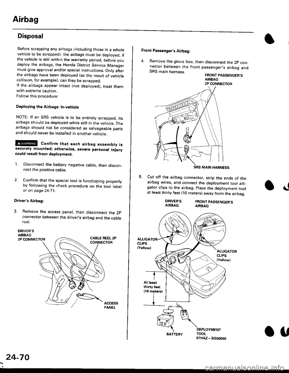
3. Remove the access panel, then disconnect the 2pconnector between the driver,s airbag and the cablereet.
DRIVER'SAIRBAG2P CONNECTOR
24-70
BATTERY.U
Front Passenger's Airbag:
4. Remove the glove box, then disconnect the 2p con-nector between the lront passenger,s airbag andSRS main harness.FRONT PASSENGER'SAIREAG2P CONNECTOB
SRS MAIN HARNESS
Cut off the airbag connector, strip the ends of theairbag wires, and connect the deployment tool alli_gator clips to the airbag. place the deployment toolat least thirty feet (10 meters) away from the airbag.
a!
DRIVER'SAIRBAGFRONT PASSENGER'SAIRBAG
ALLIGACLIPS(Yellow)ALLIGATORCLIPS{Yellowl
At loastthiny toet(10 metorsl
Page 1980 of 2189

Gauges (cont'd)
- How the Gircuit Works
When the ignition switch is in ON (ll) or START (lll),
battery voltage is supplied through fuse 25 to the
gauges in the gauge assembly.
Speedometer and Odometer
The odometer and soeedometer drive circuits
receive pulses from the vehicle speed sensor
(VSS). The pulse rate increases as the car
accelerates. The frequency and duration of these
input pulses are measured and displayed by the
speedometer, odometer and tripmeter.
Tachometer
The tachometer drive circuit receives pulses from
the ignition control module (lCM) in the distributor
assembly or the ECM/PCM. The solid-state
lachometer then displays these pulses as engine
speed. For each 200 pulses per minute from the
ignition control modul€ (lCM) or the ECM/PCM, the
tachometer displays 100 RPM.
Engine Coolant Temperature Gauge
The engine coolant temperature gauge has two
intersecting coils wound around a permanent
magnet rotor. Voltage applied to the coils, through
fuse 25, generates a magnetic lield. The magnetic
field, controlled by the coolant temperature sending
unit, causes the rotor to rotate and the gauge
needle to move. As the resistance in the sending
unit varies, current through the gauge coils
changes. The gauge needle moves toward the coil
with the strongest magnetic field.
The 6ngine coolant temperature sending unit's
resistance varies from about 137 ohms at low
engine temperature to between 3H6 ohms at high
temperature (radiator fan running).
Refer to the Service Manual (Section 23, Electrical)
for specific tests or troubleshooting procedures.
81-2
(
Fuel Gauge (All except cX)
The fuel gauge has two intersecting coils wound
around a permanent magnet rotor. Voltage applied
to the coils, through tuse 25, generates a magnetic
field. The magnetic field, controlled by the fuel
gauge sending unit, causes the rotor to rotate and
the gauge needle to move. As the resislance in the
sending unit varies, current through the gauge coils
changes. The gauge needle moves toward the coil
with the strongest magnetic field.
The fuel gauge sending unit's resistance varies
from about 2-5 ohms at full, to about 110 ohms at
empty. When you turn the ignition switch off, the
gauge remains at the last reading until you turn the
ignition switch to ON (ll) or START (lll) again,
Refer to the Service Manual (Section 23, Electrical)
for specific tests or troubleshooting procedures.
Fuel Gauge (GX)
The fuel gauge has two intersecting coils wound
around a permanent magnet rotor. Voltage applied
to the coils, through fuse 25, generates a magnetic
field. The magnetic field, controlled by the PCM,
causes the rotor to rotate and the gauge needle to
move. The PCM calculates the gas quantity in the
fuel tank by using the fuel pressure value detected
by the tuel tank pressure sensor and the fuel
temperature value detected by the fuel tank
temperalure sensor, and outputs the signal to the
gauge assembly. The gauge needle moves toward
the coil with the strongest magnetic field.
When you turn the ignition switch off , the gauge
remains at the last reading until you turn the ignition
switch to ON (ll) or START (lll) again. When the
PCM detects a malfunction with the fuel pressure or
temperature, or detects a gas leak, the PCM
reduces the fuel meter to 0.
Refer to the Service Manual GX Supplement
(Section 11 , Fuel and Emissions) for specific tests
or troubleshooting procedures.
a
a