1996 HONDA CIVIC Right air
[x] Cancel search: Right airPage 2 of 2189

INTRODUCTION
How to Use This Manual
This manual contains information for the 1996 - 2000 ClVlC. lt is
divided into 24 sections. The first page of each section is marked
with a black tab that lines up with its corresponding thumb index
tab on this page and the back cover. You can quicklY find the first
page of each section without looking through a tull table ol con_
tents. The symbols printed at the top corner of each page can also
be used as a quick reference system.
Each section includesl
1. A table of contents, or an exploded view index showing:
. Parts disassemblY sequence.
. Bolt torques and thread sizes.
. Page references to descriptaons in text
2. Disassembly/assembly procedures and tools.
3. Inspection.
4. Testing/troubleshooting.
5. Repair.
6. Adjustments.
Special Information
!@ Indicates a sttong possibility of sover. perconal iniurY
or loss ol lite if in3tructions are not follow€d.
GAUTION: Indicaiqs a possibility ot p€lsonal injury or 6quipm.nt
damage il instiuc'tions are not followod
t Noncali-. pu.po.. ot thes6 messages is to help provent demage lo lhe
vehicle, other property, or the €nvironment.
NOTE: Gives helpful information.
CAUTfON: Detaifed descriptions ol standard workshop p.oceduro3.
safoty principles and servico operations are not included. Pleaso
note that this manual contain3 wetnings and cautions against
some sp6cific sGrvic€ methods which could cause PERSONAL
INJURY, damage a vohicle or make il unsafe. Ploase undorstand
that these warnings cannot covsr all conceivable weys in which
service. whelher or not iocommgndod bY HONDA. mighi bo done,
or ol tho possiblG hazardou3 consgquonces of ev€aY conceivablg
way, nor could HONDA invqstigato all 3uch way3. AnYono using
sgrvice procedures or lools, whethei or nol rGcommendod bY
HONDA, must srtisty hifisetf thoroughlylhat nohher pefsonal sefety
nor vehiclc satsty will be reopardi2ed.
All intormation contained in this manual is based on the latest prod
uct information available at the time oI printing We reserve the
right to make changes at any time without notice No part of this
publication may be reproduced, stored in retrieval system, or trans'
mitted, in any form by any means, electronic, mechanical, photo
copying, recording, or otherwise, without the prior written permis-
sion of the publisher. This includes text, figures and tables.
*Transaxle
ds
First Edition 8/99 1848 PagesAll Right Reserved
HONOA MOTOR CO., LTD.
Sorvico Publication Offico
As sections with * include SRS components;
sDecial precautions are lequired when servlclng
*Electrical't
*SRSSRS
Page 35 of 2189

Warning/Caution Label Locations
A: CABLE REEL CAUTION A: '96 -99 model
TO SERVICE MANUAL FOR DETAILED INSTRUC.
TtoNs.
'00 model
ALLATION OF THE SRS CAELE REEL IS CRITICAL TO
THE PROPER OPERATION OF THE SRS SYSTEM. REFER TO
THE SERVICE MANUAL DETAILED INSTALLATION
INSTRUCTIONS.
(cont'd)
1-33
C: DRIVER MODULE OANGER
DANGEREXPLOSIVE/FLAMMABLECONTACT WITH ACIO. WATER OR HEAVY METALS SUCH
AS COPPER. I.EAD OR MERCURY MAY PRODUCE HARMFUL
AND IRRITATING GASES OR EXPLOSIVE COMPOUNDS,
STOBAGE TEMPERATURES MUST NOT EXCEED 2OO'F
I1(x}"CI. FOR PROPER HANDLING. STORAGE AND DISPOS.
AL PROCEDURES REFER TO SERVICE MANUAL. SRS SUP.
PLEMENT.POTSONCONTAINS POISONOUS SODIUM AZIOE AND POTASSIUM
NITRATE.FIRST AID:IF CONTENTS ARE SWALLOWED, INDUCE VOMITING, FOB
EYE CONTACT. FLUSH EYES WTTH WATER FOR 15 MINUTES.
IF GASES {FNOM ACIO OR WATEB CONTACTI ARE INHALED,
SEEK FRESH AIR. IN EVERY CASE, GET PBOMPT MEDICAL
ATTET,ITION.KEEP OUT OF REACH OF CHILDREN.
Br oRIVER MODULE WARNING
WARNINGTHE AIRBAG INFLATOR IS EXPLOSIVE AND, IF ACCIOEN-
TALLY DEPLOYEO, CAN SERIOUSLY HURT OR KILL YOU.. DO NOT USE ELECTRICAL TEST EoUIPMENT oR PROB-
ING OEVICES.THEY CAN CAUSE ACCIDENTAL DEPLOYMENT.o NO SERVICEABLE PARTS lNSlDE. DO NOT
DISASSEMBLE.. PLACE AIRBAG UPRIGHT WHEN REMOVED.. FOLLOW SERVICE MANUAL NSTBUCTIONS CAFEFULLY.
Page 37 of 2189
Llo
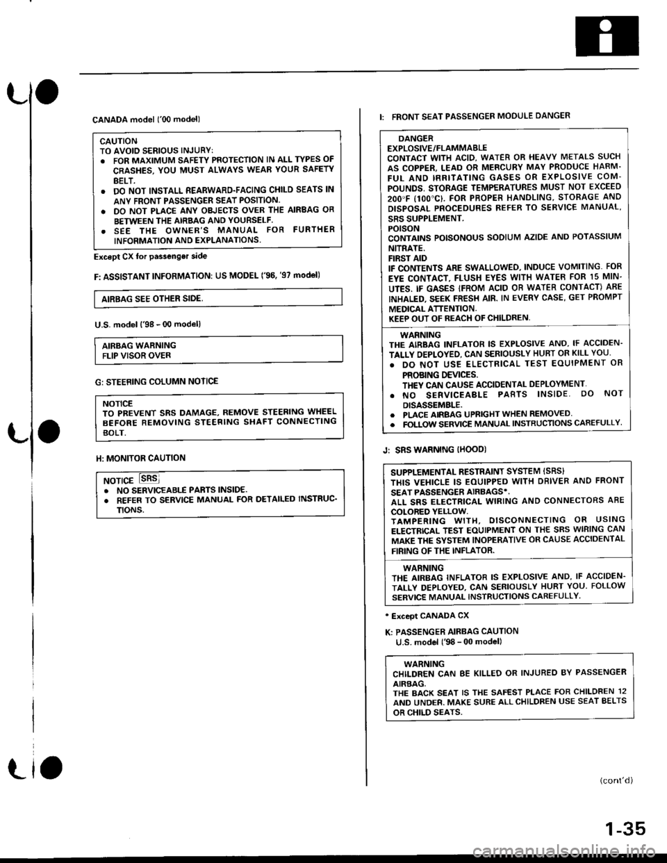
CANADA model ('00 model)
CAUTIONTO AVOID SERIOUS INJURYT. FOR MAXIMUM SAFETY PROTECTION lN ALL TYPES OF
CRASHES, YOU MUST ALWAYS WEAR YOUR SAFETY
BELT.. DO NOT INSTALL REARWARD-FACING CHILD SEATS lN
ANY FRONI PASSENGER SEAT POSITION.
. DO NOT PLACE ANY OBJECTS OVER THE AIRBAG OR
BETWEEN THE AIRBAG AND YOURSELF.. SEE THE OWNER'S MANUAL FOR FURTHER
INFORMATION AND EXPLANATIONS.
Except Cx tor passenger side
F: ASSISTANT INFoRMATION: US MODEL ('96. '97 mod€l)
AIRBAG SEE OTHER SIDE,
U.S. model l'98 - 00 modell
AIRBAG WARNINGFLIP VISOR OVER
Llo
G: STEERING COLUMN NOTICE
NOTICETO PBEVENT SRS DAMAGE, REMOVE STEERING WHEEL
BEFORE REMOVING STEERING SHAFT CONNECTING
BOLT.
ll: MONITOR CAUTION
NOTICE. NO SERVICEABIf PABTS lNSlDE.. REFER TO SERVICE MANUAL FOR DETAILED INSTRUC'
TtoNs.
DANGEREXPLOSIVE/FLAMMABLECONTACT WITH ACID, WATER OR HEAVY METALS SUCH
AS COPPER, LEAD OR MERCURY MAY PRODUCE HARM.
FUL AND IRRITATING GASES OR EXPLOSIVE COM-
POUNDS, STORAGE TEMPERATURES MUST NOT EXCEED
2OO'F I1OO"C}. FOR PROPER HANOLING, STORAGE AND
DISPOSAL PNOCEDURES REFER TO SERVICE MANUAL'
SRS SUPPLEMENT.POISONCONTAINS POISONOUS SODIUM AZIDE AND POTASSIUM
NITRATE.FIRST AIDIF CONTENTS ARE SWALLOWEO, INDUCE VOMITING. FOR
EYE CONTACT, FLUSH EYES WITH WATEB FOR 15 MIN-
UTES. IF GASES IFROM ACID OB WATER CONTACT) ABE
INHALED. SEEK FRESH AIR. IN EVERY CASE, GET PROMPT
MEDICAL ATTENTION.KEEP OUT OF REACH OF CHILDREN,
WARNINGTHE AIRBAG INFLATOR IS EXPLOSIVE AND, IF ACCIDEN-
TALLY OEPLOYED, CAN SERIOUSLY HUBT OR KILL YOU.
. DO NOT USE ELECTRICAL TEST EOUIPMENT OR
PROBING DEVICES.TH€Y CAN CAUSE ACCIDENTAL DEPLOYMENT'
. NO SERVICEABLE PABTS lNSlDE. oO NoT
DISASSEMBLE.. PLACE AIRBAG UPRIGHT WHEN REMOVED. FOLTOW SERVICE MANUAL INSTRUCTIONS CAREFULLY
I: FRONT SEAT PASSENGER MOOULE DANGER
Jr SRS WARNING IHOOD)
' Exceot CANADA CX
K: PASSENGER AIRBAG CAUTION
u.S. model l'98 - 00 model)
WARNINGCHILDREN CAN 8E KILLED OR INJUREO BY PASSENGER
AIRBAG,THE BACK SEAT IS THE SAFEST PLACE FOR CHILDREN 12
AND UNDER. MAKE SURE ALLCHILDREN USE SEAT BELTS
OR CHILD SEATS.
(cont'd)
1-35
SUPPLEMENTAL RESTRAINT SYSTEM ISRS}
THIS VEHICLE IS EOUIPPED WITH DBIVER AND FRONT
SEAT PASSENGER AIRBAGS'.ALL SRS ELECTRICAL WIRING AND CONNECTORS ABE
COLORED YELLOW.TAMPERING WITH, DISCONNECTING OR USING
ELECTRICAL TEST EOUIPMENT ON THE SRS WIRING CAN
MAKE THE SYSTEM INOPERATIVE OR CAUSE ACCIDENTAL
FIRING OF THE INFLATOR.
WARNINGTHE AIRBAG INFLATOR IS EXPLOSIVE AND, IF ACCIDEN.
TALLY DEPLOYED, CAN SERIOUSLY HURT YOU. FOLLOW
SERVICE MANUAL INSTRUCTIONS CAFEFULLY'
Page 125 of 2189
Valve Seals
Replacement (Cylinder head removal not requiredl
NOTE: Cylinder head removal is not required in thisprocedure.
The procedure shown below applies when using the in-
car valve spring compressor (Snap-on YA884S withY48845 - 2 A7/8" attachment).
!@@ Alway wear approved eye protection whenusing ihe in-cai valve spring compressor.
1. Turn the crankshaft so that the No. I and the No. 4pistons are at top dead center (TDC).
2. Remove the cylinder head cover and the rocker arm
assembly.
NOTE:
. Refer to page 6-30 for rocker arm assembly
removat.
. When removing or installing the rocker armassembly, do not remove the camshaft holder
bolts. The bolts will keep the holders, springs
and rocker arms on the shaft.
. Refer to page 6-46 when installing the cylinder
head cover.
Remove the fuel injectors and the wire harness.
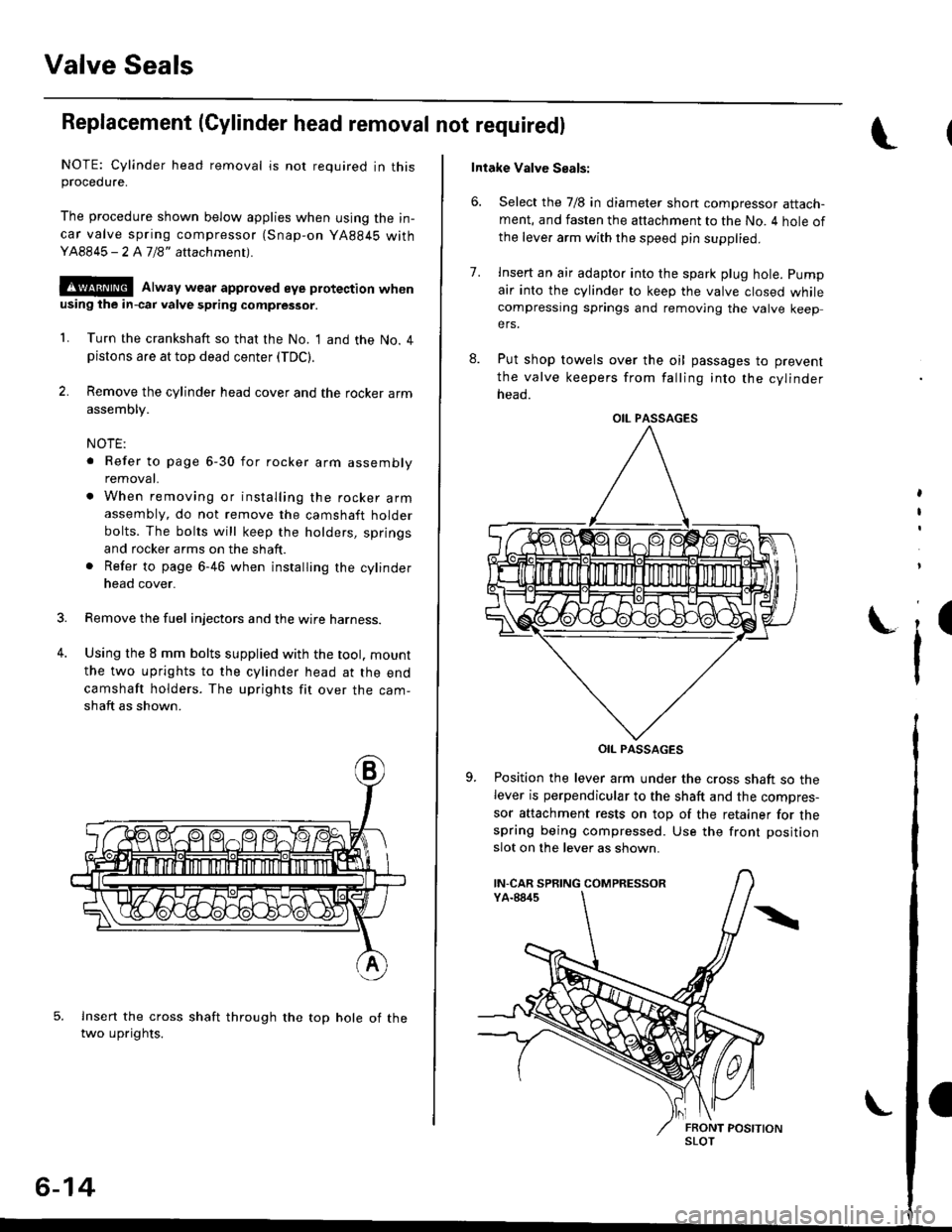
Using the 8 mm bolts supplied with the tool. mount
the two uprights to the cylinder head at the end
camshaft holders. The uprights fit over the cam-
shaft as shown.
lnsert the cross shaft through the top hole of thetwo uprights.
3.
4.
6-14
Intake Valve Seals:
6. Select the 7/8 in diameter short compressor attach-ment, and fasten the attachment to the No. 4 hole of
the leve. arm with the speed pin supplied.
8.
7.lnsert an air adapto. into the spark plug hole. pump
air into the cylinder to keep the valve closed whilecompressing springs and removing the valve keepers.
Put shop towels over the oil passages to prevent
the valve keepers from falling into the cylinder
neao.
OIL PASSAGES
Position the lever arm under the cross shaft so thelever is perpendicular to the shaft and the compres-
sor attachment rests on top of the retainer for thespring being compressed. Use the front position
slot on the lever as shown.
,
I
i'
OIL PASSAGES
IN-CAR SPRING COMPRESSOR
SLOT
Page 353 of 2189
Troubleshooting
Troubleshooting Procedures (cont,dl
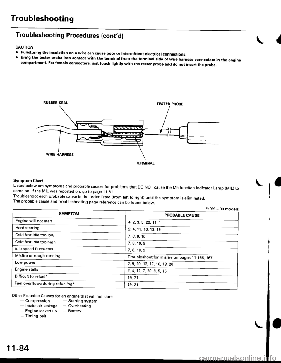
CAUTION:
. Punqturing ihe insulation on a wirs can cause poor or intermiftent electricar connections.I Bring the test€r probe into contacl with the terminatlrom the terminal side of wire harnesg conncctors in the gngin€compartment. For temale connectors, iust touch lightly with the tester probe and do not inse.t the probe.
\I
RUBBER SEAL
Other Probable Causes for an engine that will not start:- Compression- Starting system- lntake air leakage - Overheating- Engine locked up - Battery- Timing belt
TESTER PROBE
Symptom Chart
Listed below are symptoms and probable causes for problems that Do NoT cause the Malfunction indicator Lamp (MlL) tocome on. lfthe MIL was reported on, go to page 11_81.Troubleshoot each probabre cause in the order risted (from reft to right) untir the symptom is eriminated.The probable cause and troubleshooting page reference can be found berow.
L
*: '99 - 00 models
TERMINAL
SYMPTOMPROBABLE CAUSE
4,2,3, 5,20, 14, 1
2, 4, 11, 16, 13, 't9
?, s^6. 16
1,8,10.9
Engine will not sta rt
Hard starting
Cold fast idle too low
Cold fast idle too high
ldle speed fluctuates7,8, 10.9
Troubleshoot for misfire on pages l1-166, 167Misfire or rough running
LOW power
E"g|* "t"lb
2,9, 10, 12, 11, 16, 't8,20
2,4,11,7,20,8,5,15
't9, 21
1r, ,1
Difficult to refuel*
Fuel overflows during refueling*
11-84
Page 422 of 2189
Secondary Heated Oxygen Sensor {secondary HO2S) (Sensor 2l
*'t : D16Y8 engine*2:'99 - O0 m;dels except D16Y5 engine with M//T
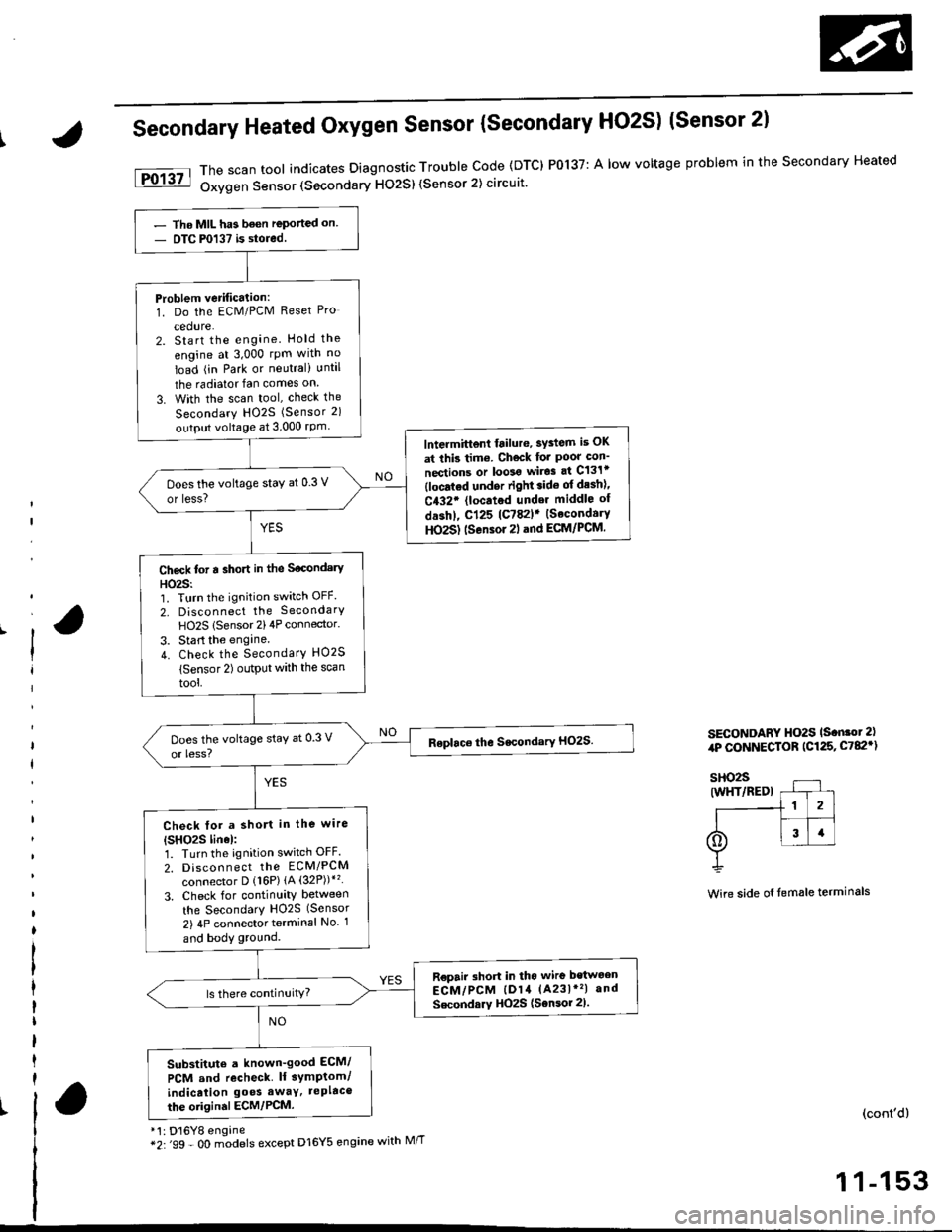
The scan tool indicates Diagnostic Trouble Code (DTC) P0137: A low voltage problem in the Secondary Heated
Oxygen Sensor (Secondary HO2S) (Sensor 2) circuit'
SECONDARY HO2S ls.n.ot 2),rP CONNECTOR (C125, C782')
Wire side oI temale terminals
(cont'd)
1 1-153
- Tho MIL has been reported on- DTC P0137 is stored.
Problem verification:1. Do the ECM/PCM Reset Pro
cedure.2. Start the engine. Hold the
engine at 3,000 rpm wlth no
load (in Park or neutral) until
the radiator fan comes on
3. With the scan tool, check the
Secondary HO2S (Sensor 2)
output voltage at 3,000 rPm
lntermittent frilure, sYdem is OK
at this tim6. Check for Poor con'
nections or loolo wir.3 at C131t(locatod undor right.ido of desh)'
C432. {located under middle of
dashl, cl25 lc782lr {SecondaryHO2S) tsensor 2l .nd ECM/PCM.
Does the voltage staY at 0.3 V
or less?
Ch6ck tot a sho.t in the S€condery
HO23:'1. Turn the ignition switch OFF.
2, Disconnect the SecondarY
HO2S lSensor 2)4P connector.
3. Start the engine.
4. Check the SecondarY HO2S
lsensor 2) output with the scan
tool,
Check tor a short in the wire
{SHO2S linel:1. Turn the ignition switch OFF.
2. Discon n ect tho EcM/PCM
connector D {16P) {A (32P))*'�
3. Check for continuity between
the SecondarY H02S (Sensor
2) 4P connector terminal No 1
and body ground.
R€pair short in tho wire bstwoen
ECM/PCM lD14 (A231*'�| and
Secondarv HOzS (Sensor 2).
Substitute a known-good ECM/
PCM and recheck lf 3ymptom/
indicalion go€s awaY, tePltco
the oiigin.l ECM/PCM.
Page 423 of 2189
PGM-FI System
I
a
a
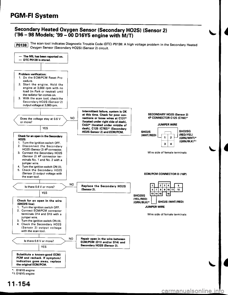
9ggoqOfry Heated Oxygen Sensor (Secondary HO2S) {sensor 2l('96 - 98 Models; '99 - 00 D16YS engine with M/Tl
The scan tool indicates Diagnostic Trouble Code (DTC) PO'138: A high voltag€ problem in the Secondary HeatedOxygen Sensor (Secondary HO2SI (sensor 2) circuit.
SECONDARY HO2S ls.nsor 2l4P CONNECTOR C125 tc782t*
JUMPER WIRE
sHo2sIWHT/RED}
sHo2sG(RED/YEL)(GRN/WHT)*(GRN/BLK)*'
Wire side of female terminals
ECM/FCM CONN€CTOR D Il6PI
sH()2sG{YEL/RED){GRN/BLK}'
JUMPER WINE
Wire side of female terminals
'i D16Yg engine*1i Dl6Y5 engine
- Ths MIL ha3 bcen r6port.d on.- DTC m138 i. 3tored.
Problem vorilication:1. Do the ECM/PCM Reset Pro-cedure.2. Start the engine. Hold theengine at 3.000 rpm with noload (in Park or neutral) untilthe radiatorfan comes on.3. With the scan tool, ch€cktheSecondary HO2S {Sensor 2)outputvoltageat 3,000rpm.
Into.mittant failurc, sy3tem b OKrt thi3 tims. Ch6ck tor poor con-n6clionr or loo3€ wiroa at C13'l*(locat d und6r right lido of dr'h),C/€2r (loc.tod und€r middle old.rhl, C125 {C782lr (Socond.ryHO2S S6n3or 2) .nd ECM/PCM.
Chcd( for rn open in the Socond!ryf|o2s:1. Turn the ignition switch OFF.2. Disconnect the SecondaryHO2S (Sensor 2) 4P connector.3. Connect the Secondary HO2S(Sensor 2) 4P connector ter-minals No. 1 and No.2 with aJUmper wire.4. Tu.n the ignition switch ON (ll).5. Chock the Secondary HO2S(Sensor 2) output vollage withthe scan tool.
ls there 0.6 V or more?
Check tor an open in the wiro(SHO2S lin6l:1. Turn th6 ignition switch OFF.2. Connect ECM/PCM connectorterminals D14 and D13 with ajumper wire.3. Turn the ignition switch ON {ll}.4. Check the Secondary HO2S(Sensor 2) oltput voltagewith the scan tool.
Rapair op.n in the wiio botw.onECM/PCM lD13 and/or Dlal andS.cond.ry HO2S ls€nsor 21.
ls thore 0.6 V or more?
Subslituto a known-good ECM/PCM .nd rccheck. lt symptom/indication goe! rway, replacethe original ECM/PCM.
11-154
Page 424 of 2189
Secondary Heated Oxygen Sensor (SecondarytlO2S) (Sensor 2l
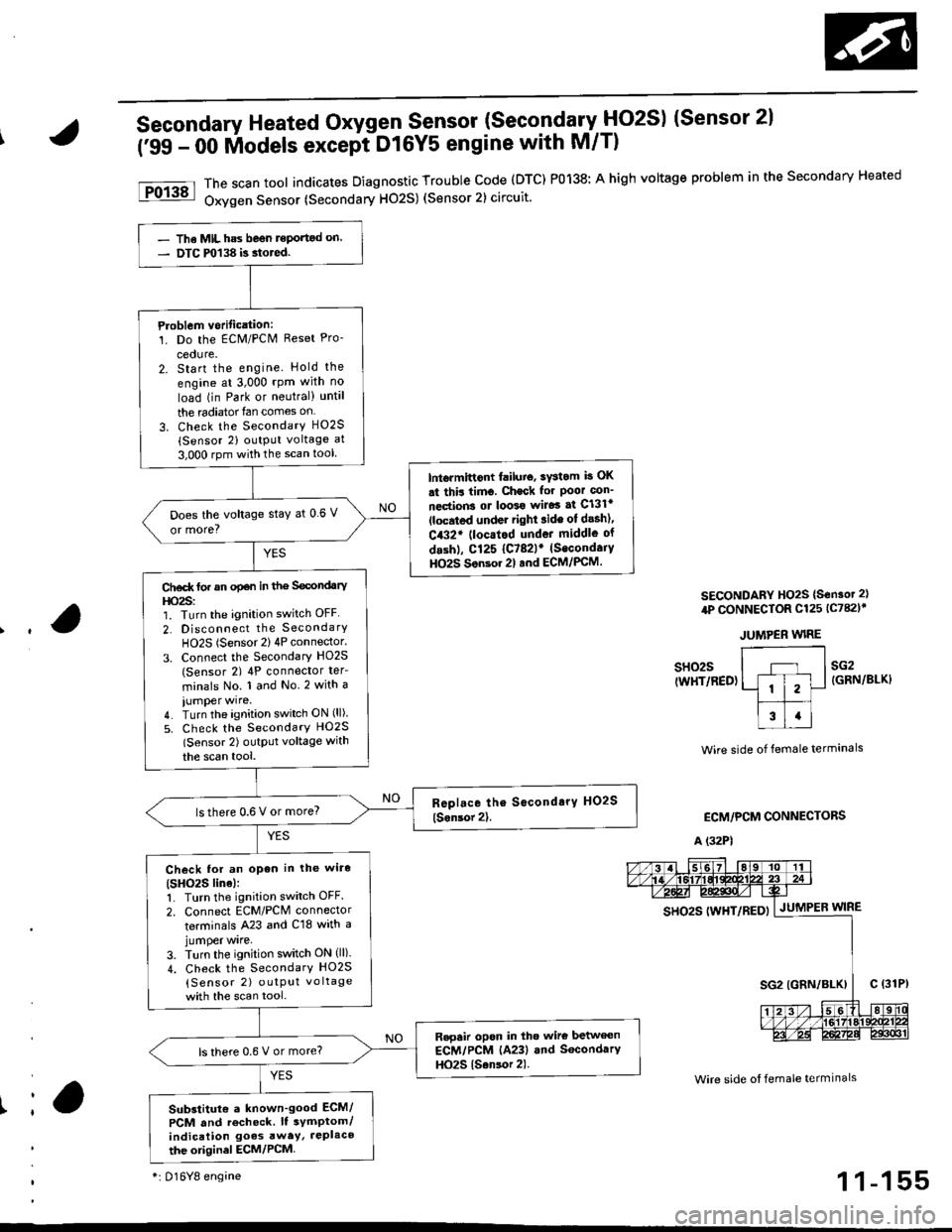
('99 - 00 lilodels except DtGYS engine with M/T)
The scan tool indicates Diagnostic Trouble code (DTC) P0138: A high voltage problem in the secondary Heated
Oxygen Sensor (Secondary H02S) (Sensor 2) circuit.
SECONDARY HO2S {S€nsot 2}
4P CONNECTOR Cl25 lc782l'
JUMPER WIRE
Ir
sH02s(WHT/RED)sG2{GRN/BLKI
Wire side of female termanals
ECM/PCM CONNECTORS
A (32P1
Wire side ot female termlnals
gs92g 111yp17p5py | .lutuPea wtne
- The MIL has beon reportod on.- DTC m138 is.tored.
Ploblem vorification:1. Do the ECM/PCN4 Reset Pro-
cedure.2. Start the engine Hold the
engine at 3,000 rpm with no
load (in Park or neutral) until
the radiator{an comes on
3. Check the SecondarY H02S(Sensor 2) output voltage at
3,000 rpm with the scan tool
lntormittont failuio, sYstom b OK
st thir timo. Check for Poor con_
nections ot loo39 wiJo3 af Cl3lr(located under right ride ot desh),
C432' (locatod undot middle of
dashl, Cl25 {C782lr (Secondaiy
HO2S Son3or 2l and ECM/PCM.
Does the voltage stay at 0 6 V
or more?
Ct€d( tor an opan in the Secondary
l|o2s:1. Turn the ignition switch OFF
2. Disconnect the SecondarY
HO2S (Sensor 2) 4P connector.
3. Connect the Secondary HO2S(Sensor 2) 4P conneclor ter_
minals No. 1 and No.2 with a
iumper wire.4. Turn the ignition switch ON (ll)
5. Check the SecondarY HO2S
lSensor 2) outptlt voltage with
the scan tool,
lsthere 0.6 V or more?
Check lor an open in the wiro(SHO2S line):1. Turn the ignition switch OFF.
2. Connect ECM/PCM connector
terminals A23 and C18 with ajumper wrre,
3. Turn the ignition switch ON (ll).
4. Check the SecondarY HO2S
{Sensor 2) outPut vo ltage
with the scan tool.
Repair opon in tho wire betwecn
ECM/PCM (A23) and SocondarY
HO2S {Sansor 2).ls there 0.6 V or more?
Substitut€ a known'good ECM/
PCM and recheck. It symptom/indication goes awey, JePlaco
the otiginel ECM/PCM
*i 016Y8 engine1 1-155