1996 HONDA CIVIC 11-216
[x] Cancel search: 11-216Page 270 of 2189

!
Fuel and Emrsslons
SoecialToofs .....,...."..,. 11-2
Component Locations
lndex ....................., ......... 11-3
Svstem Description
Vacuum Connections ................,,..,.. ......... 11-12
Electrical Connections ...............,.,.,... ....... 11-29
System Connectors ........,.,.,.......................... 1 1-51
Troubleshooting
Troubleshooting Procedures ................. .. 11-81
Engine Control Module/PowertrainControl Module TerminalAfiangement ....,.,..... 11-88
Diagnostic Trouble Code Chart .................,., 11.97
How to Read Flowcharts .,.......................... . 11-103
PGM-Fl System
System Description ...... 11-10,1
Troubleshooting Flowcharts
Engine Control Module/PowertrainContlol Module ........ 11-107
Manitold Absolute Pressure Sensor .....'. . ... 11-115
fntake Air Temperatuie Sensor ..... . . ., . 11'121
Engine Coolant Temperatuae Sensol ........., 11-128
Throttle Position Sensor ...................,........... 11-132
Primary Heated Orygen Sensor (Sensor 1l ... 11-139
Secondary Heated Oxygen Sensor(Sensor 21.................................................... 1 1-153
Heated Oxygen Sensor Heater ...................,. 11-157
Fuel Supply System ...... 11-164
Random Mislire ......., ..11-166
Misfire Detected in One Cylindsr ................. 11-167
Knock Sensor .,.,............ 11-170
CKP/TDC/CYP Sensor ................................... 11'172
Vehicle Speed Sensor ...........,......,...,.,........... 1t-176
Barometric Pressure Sensor ...............,......... I 1-178
Electrical Load Detector,.,,............................ 1 1-179
CKF Sensor .................... 11-183
ECM/PCM Internal Circuit ............................. I 1-188
A/T Signal {TMA/TMBI .................................. I 1-189
ldle Control System
System Doscriplion ............ 11-190
Troubleshooting Flowcharts
ldle Control System ...... 11-192
ldle Air Control Va1ve .................................... I 1-19i1
Starter Switch Signal .................................... 1 1'202
Air Conditioning Signal ................................. 11'201
Ahernator FR Signal .................................... . 1 1-208
BrakeSwitch Signal ..................................... f 1"210
Power Sleering Prossure Switch Signal ......11-212
A/T Gear Position Signal ............................... 11-216
Clutch Swiich Signal ................................-.... 11-214
ldte Speed Setting . .............11-220
Fuel Supply System
Fuel Lines .,...................,.,.,.,11-221
Fuef Tube/Ouick-Connect Fittings ..........,.,........ 11 -227
System Description ....'.... 11-230
Fuel Pressure .......,.,,........... 11-230
Fuef fniectors ......................11-232
Fu€f Pressure Regulator .....,.......................'...,. 11-231
Fuef Fifter ............................11-235
Fuel Pump .............'.......'.... 11-236
PGM-FI Main Relay .............11'237
Fuel Tank ................ ....,...'.'.' 11'211
Intake Air System
System Description ....-.-.....11-243
Air Cfeaner ...........,......."". .11-211
Throttle Cable .....................11-211
Throttfe Body ........ ..'... . . .,.11-211
Fuel Iniestion Air Control System ,.,.,....-........... 11-250
Emission Control System
System Description .-..........11-252
Taifpip€ Emission ...............11-252
Three Way Catafytic Convert€r ............,.,,.,.,.,.... 11 -252
Exhaust Gas Racirculaiion System ...,.,,,,.,.,.,.,,. 11'254
Positive Crankcas€ Ventilation System .... . . .. 11-266
Evaoorative Emission Controls ..................,,..,.,. 11 -267
Page 354 of 2189

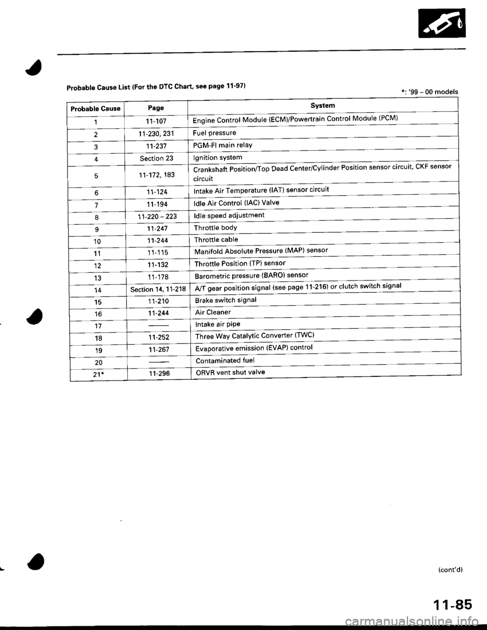
Probable Cause List lFor th€ DTC Chart, see page 11-971*: '99 - 00 models
Probable GausePageSystem
11 1-107Engine Control Module (ECM)/Powertrain Control Module (l'uM)
PGM-Fl main relay
l^^iti^n cwetam
211-230,231
3't't-237
Section 23
51'�1-172,183Crankshaft Position/fop Dead Center/Cylinder Fosltlon sensor clrculr'� Lr\F selrsor
circuit
Intake Air Temperature (lAT) sensor circuit
ldle Air Control (lAC) Valve
ldle speed adjustment
Throttle bodY
Throftle cable
Manifold Absolute Pressure (MAP) sensor
Throftle Position (TP) sensor
Barometric pressure (BARO) senso'
Mf g"a, po"ition signal (see page 11-216) or clutch switch signal
Brake switch signal
Air Cleaner
lntake air pipe
Three Way Catalytic Converter (TWC)
Evaporative emission (EVAP) control
Contaminated fuel
ORVR vent shut valvs
't1-124
71 1-194
I11-220 - 223
11-241
'1011-244
1111-115
1211-132
13't1-178
14Section 14. 11-218
1511-210
16't1-244
1811-252
1911-261
20
21*11-296
(cont'd)
11-85
Page 460 of 2189

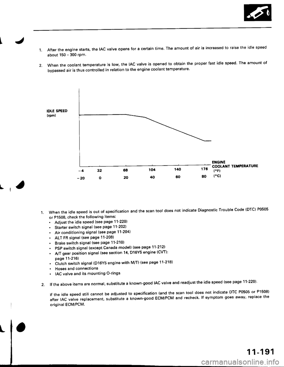
1.After the engine starts, the lAc valve opens for a certain time. The amount of air is increased to raise the idle speed
about 150 - 300 rpm.
When the coolant temperature is tow, the IAC valve is opened to obtain the proper fast idle speed. The amount of
bypassed air is thus controlled in relation to the engine coolant temperature'
IOLE SPEED
lrpml
176
80
ENGI ECOOLANI TEMPERATURE
t" Fl
toc)
ll
't.Whentheid|espeedisoutofspeciiicationandthescantoo|doesnotindicateDiagnosticTroub|ecode(DTc)P0505
or P1508. check the following items:
. Adiust the idle speed {see page 11-220}
. Starter switch signal (see page 11-202)
. Air conditioning signal (see page l1-204)
. ALT FR signal (see Page 11-2081
' Brake switch signal (see page 11-210)
. PSP switch signal (excapt Canada model) (see page 11-212)
. A,/T gear position signal {see section 14, Dl6Y5 engine (CVT):
page 11-216). Clutch switch signal (D16Y5 engine with M/T) (see page 11-218)
. Hoses and connections
' IAC valve and its mounting O-rings
lf the above items are normal, substitute a known-good IAC valve and readjust the idle speed (see page 11-220)
|ftheid|espeedsti||cannotbeadjustedtospecification(andthescantoo|doesnotindicateDTcP0505orP]50S)
after IAC valve replacement. substitute a known-good ECM/PCM and recheck. lf symptom goes away, replace the
original ECM/PCM.
Page 485 of 2189

ldle Control System
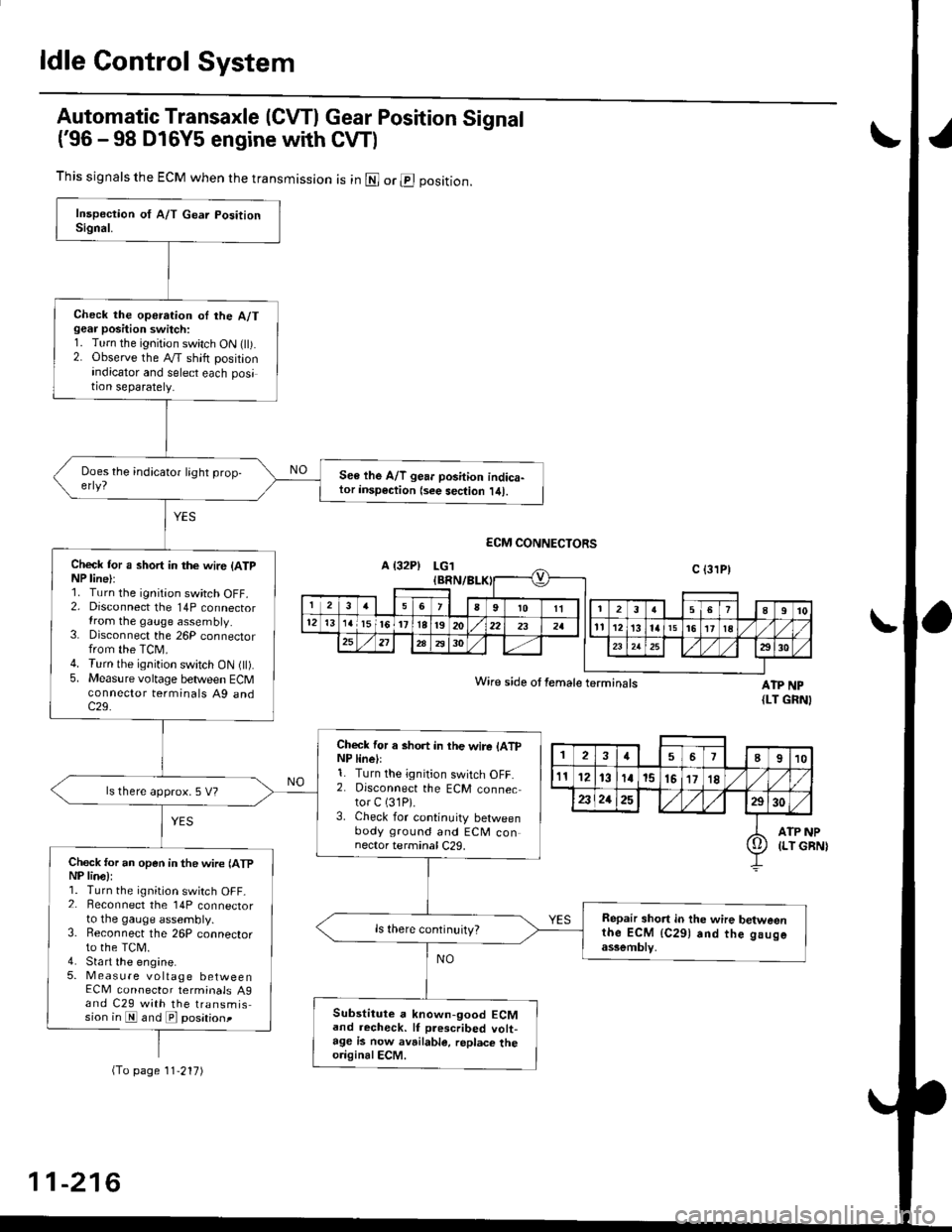
Automatic Transaxle (CVTI Gear Position Signal
('96 -98 D16Y5 engine with CW)
ATP NP{LT GRNI
INP
GBN)
This signals the ECM when the transmission is in @ or @ position.
Check the operation oI the A/Tgear position switch:1. Turn the ignition switch ON flt).2. Observe the A/T shift positionindicator and select each position separately.
See lhe A/T gear position indica-tor insp€ction {see sec{ion l/tl.
Check tor a short in the wir6 (ATpNP line):1. Turn the ignition switch OFF.2. Disconnect the 14P connectorIrom the gauge assembly.3. Disconnect the 26P connectorfrom the TCM.4. Turn the ignition switch ON fll).5. Measure voltage between ECMconnector terminals A9 andc29.
Check for a short in the wire lATpNP linell1. Turn the ignition switch OFF.2. Disconnect the ECM connector C (31P).
3. Check for continuity betweenbody ground and ECM connector terminal C29.
ls there approx. 5 V?
Check for an open in the wire lATpNP lina):1. Turn the ignition switch OFF_2. Beconnect the 14P connectorto the gauge assembly.3. Reconnect the 26P connectorto the TCM.4. Sta rt the engine.5. Measure voltage betweenECM connector terminals A9and C29 with the transmission in E and E posationt
Repair short in the wire betweenthe ECM {C291 and the gaugeassemblv,
Substitute a known-good ECMand recheck. lf prescribed volt-age is now avrilable, replace theo.iginalECM.
Wire side ot female terminals
2457I910
t112131a15151718
2321252930
ATP(LT io
(To page 11'217)
11-216
Page 486 of 2189

t
L
(From page 11-216)- Repair open in the wire
between the ECM {C291 and
lhe Ituge assomblv.- Repair open in the wire
betwoen the gauge assembly
and the A/T gea. Positionswitch.
ls there less than 1.0 V?
Chock for a short in the wite (ATP
NP line):Measure voltage between ECM
connector terminals Ag and C29
with the transmission in gear.
ReDair short in the wire be'tween
ECM (C291 and gauge a3somblY.ls there battery voltage?
A/T g€ar position signal is OK
LG1 IEBN/BLK)
ECM CONNECTORS
ATP NPWire side of female terminals (LT GRN)