Page 925 of 2189
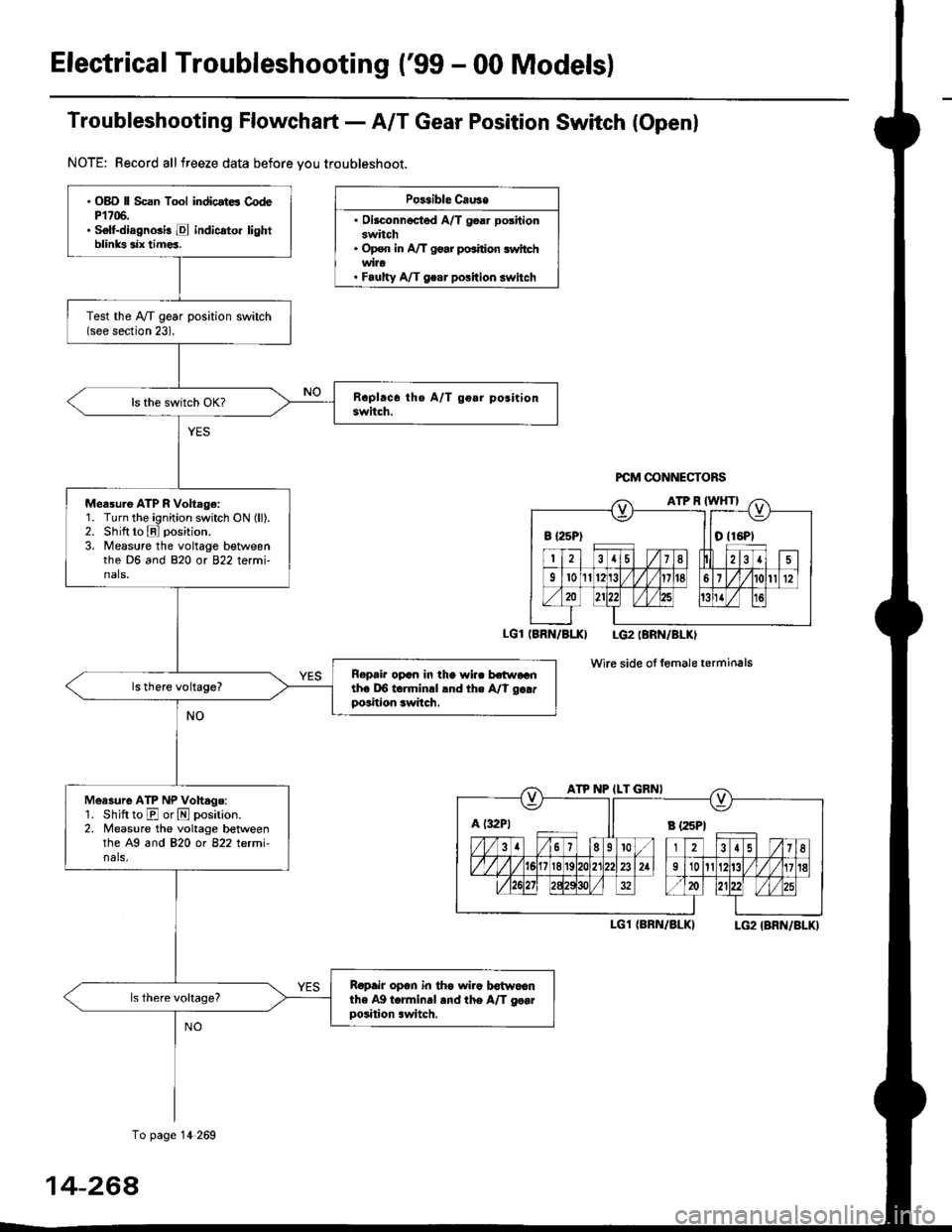
Electrical Troubleshooting ('96 - 9g Models)
Troubleshooting Flowchart - lgnition Coil
NOTE: Record all freeze data before you troubleshoot,
Po3rible Cause
. Dbconnected ignition coil con-nectol. Short o. op6n ignition coil wire' F.ulty ignition coil
Wire side ot female terminals
. OBD ll Scan Tool indicates CodePOl25.. Soll-diagnosis E indicarol lightindicates Code 11.
Measure NE Voltrge:1. Disconnect the A {26p) connector from the TCM.2. Start the engine.3. Measure the voltage betweenthe A5 and 413 or A26 termi-nals,
R6p.i. open or short in the wireb€lween the A5 te.minsl and thoignhion coil. It wir€ b OK, checkthe ignition coil test lsoc aoction23t.
ls there battery voltage?
Check for loose TCM connector.It nec$sery. substilute a known-good TCM and .echeck.
Page 945 of 2189

Electrical Troubleshooting {'99 - 00 Models)
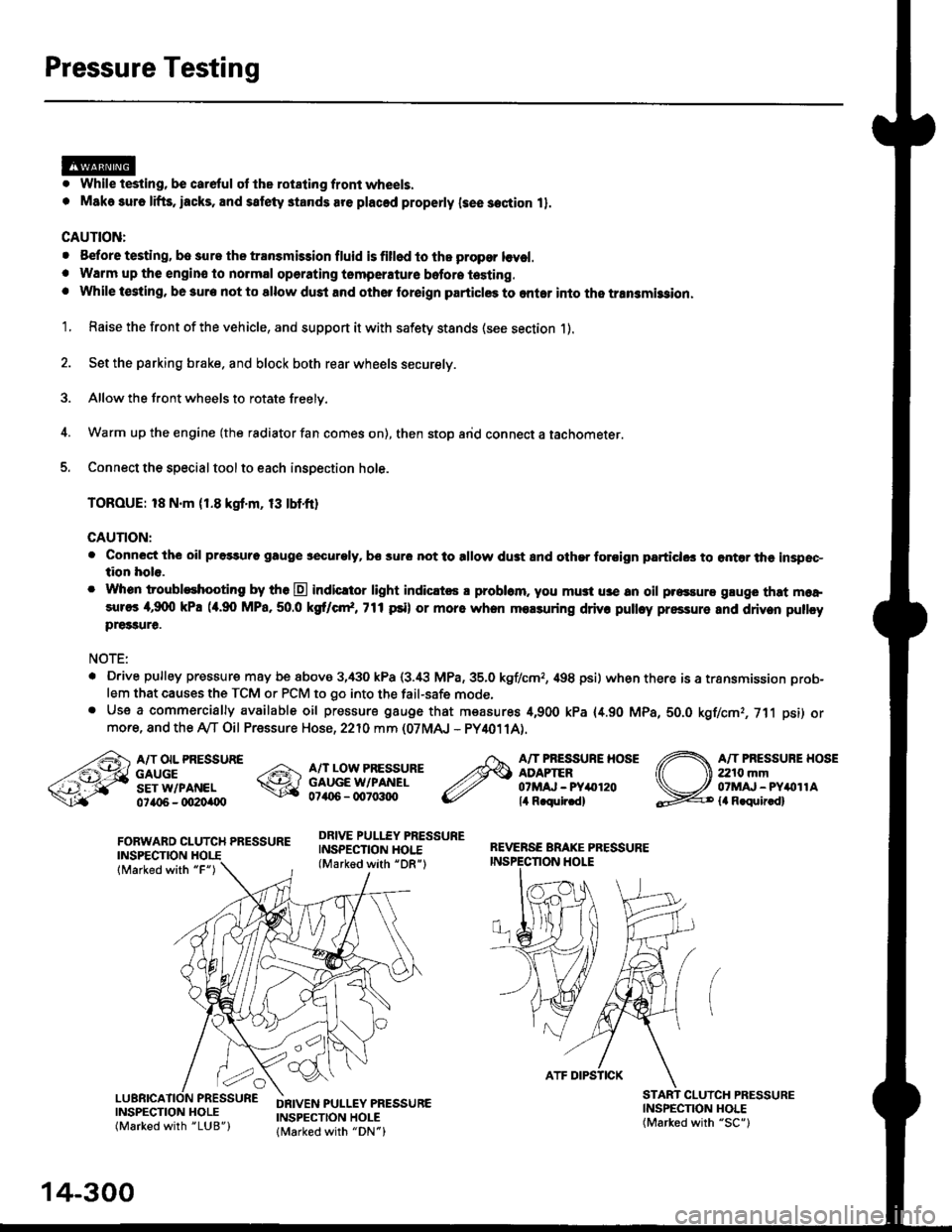
Troubfeshooting Flowchaft- AIT Gear Position Switch (Openl
NOTE: Record allfreeze data before vou troubleshoot.
Po$ible Cau3e
. Oilconnected A/T goar positionswitch. Op€n in A/T go.r po.ition switchwi?o. Faulty A/T gear polition switch
PCM @NNECTORS
(BRN/BI.XI LG2IBRN/BLKI
wire side of fomale terminals
I-G1 (BRN/BLKILG2 {BRN/BLK)
B {25P) I tO (16P1
ATP NP ILT GRNI
A t:r2Pt Il s tzspt
. OBD ll Scan Tool indicstE CodeP1706.. Selt-diagnGi! E indicato. lightblinks six tim€a.
Test the IVT gear position switch(see section 23).
Measu.e ATP R Voltage:1. Turn the ignition switch ON (ll).2. Shift to E position.
3. Measure the voltage betweenthe D6 and 820 or 822 termi-nals,
Ropair opcn in the wi.. hr.raGnth6 DO torminrl lnd the A/t g..rposition awitch.
Measure ATP NP Vohage:'1. Shift to E or N position.2. Measure the voltage betweenthe A9 and 820 ot 822 letmi-nals,
Ropair op6n in th€ wiro b€{woanthe Ag t.rminal and the A/T go..position .witch.
To page 14 269
14-264
Page 977 of 2189

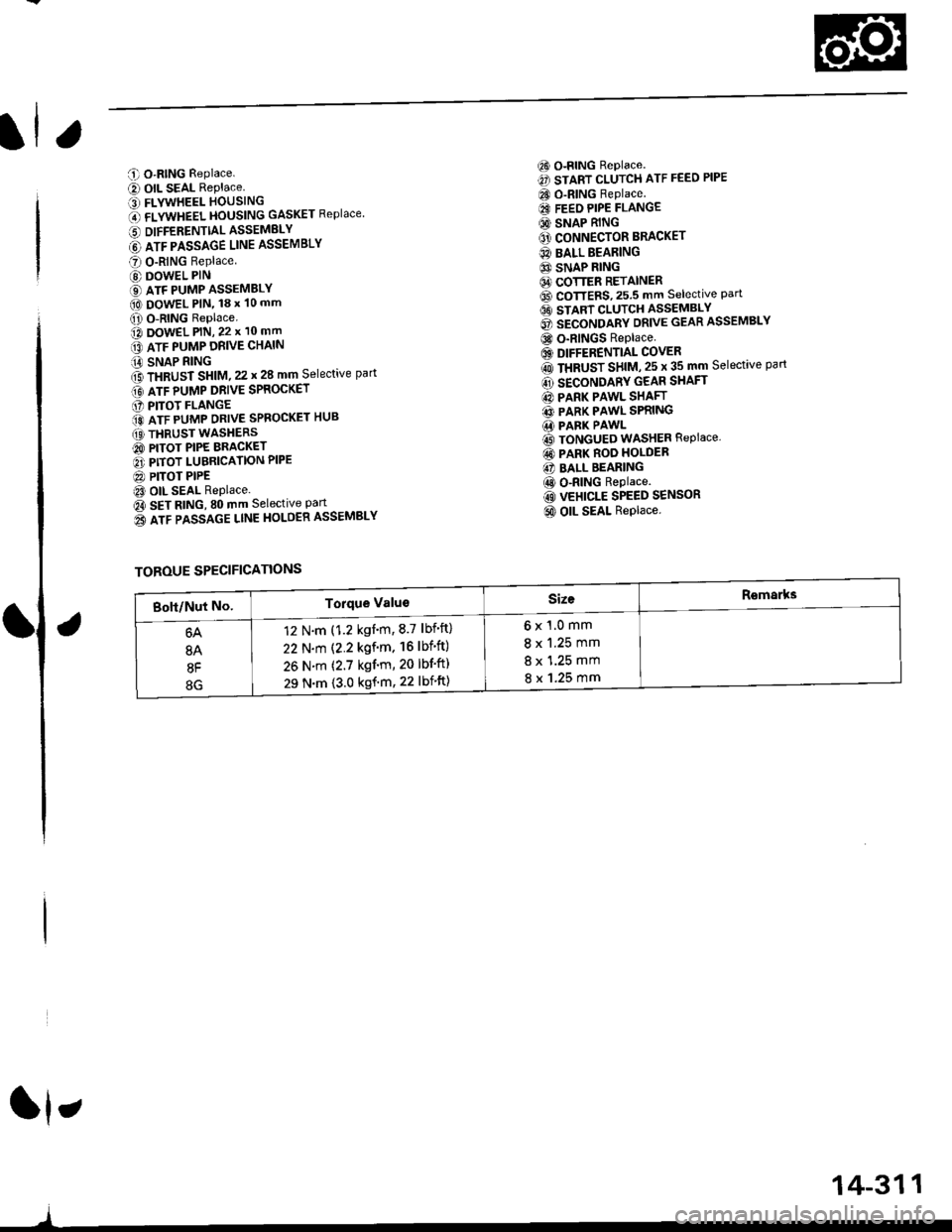
Pressure Testing
. While testing, be careful of the rot8ling front wheels.
. M8k6 suro lifts, iacks, and satety stands are placed properly lsee section 11.
CAUTION:
. Before testing, be sur. the transmb3ion fluid is fillod to the propor lcvel.. Warm up the engin€ to nolmal operating tsmperature bofore testing. While t€sting, be 3ure not to allow dust and other loreign particles to onler into the transmi$ion.
1. Raise the front of the vehicle, and support it with safety stands (see section 1).
2. Set the parking brake. and block both rear wheels securely.
3. Allow the front wheels to rotate freely.
4. Warm up the engine (the radiator fan comes on), then stop arid connect a tachometer.
5. Connect the special tool to each inspection hole.
TOROUE: 18 N.m (1.8 kgt'm, 13 tbtfr)
GAUTION:
. Connect the oil pressuro gauge !!€curoly, bs sur6 not to allow dust and other foroign particlG3 to ontar the inspsc-tion hole.
. Whon troubleshooting by tho E indicltor light indic.t6 a problam. you mu3t u3e an oil p.essure gluge that moa,sures 4,9(X) kPa (a.90 MPa,50.0 kS cr*,771psi) or more when molsuring driv. pulley pressure and driven pullcypre33ure.
NOTE:
. D.ive pulley pressure may be above 3,430 kPa (3.i8 MPa,35.0 kgf/cmr, 498 psi) wh€n there is a transmission prob-
lem that causes the TCM or PCM to go into the fail-safe mode,. Use a commercially available oil pressure gauge that measures 4,900 kPa {4.90 MPa, 5O.O kgf/cmr, 711 psi) ormore, and the Ay'T Oil Pressure Hose, 2210 mm (07MAJ - PY4011A).
FORWARD CLUTCH PRESSUREINSPECTION
lMarked with "F")
REVERSE BRAKE PRESSUREINSPECTION I.IOLE
A/T OIL PRESSUREGAUGESET W/PANEL0ta{r6 - oO2Oi|(Xt
A/T LOW PRESSUREGAUGE W/PANEL0706 - qt7o:t{ro
DRIVE PULLEY PRESSUREINSPECTION HOI.E(Marked with "DR")
A/T PRESSURE HOSEADAPTER07MAJ - PYar'120lil R.qulr.d)
A/T PRESSUBE HOSE2210 mm07MAJ - PYitollAla R.quir.d)
(
INSPECNON HOLE(Marked with "SC")
CLUICH PRESSURE
INSPECTION HOLE(Marked with "LUB")
DRIVEN PULLEY PRESSUREINSPECTION HOLElMarked with "DN")
14-300
ATF DIPSTICK
Page 983 of 2189

Transmission
Removal (cont'd)
10. Remove the cotte. pins and castle nuts, then separatethe ball joints from the lower arm (see section 1g).
SELF-LOCKING -=V,
NUT \Replace. oitupea rOax
Remove the right damper fork bolt, then separateright damper fork and damper.
Pry the right and left driveshafts out of the differen-tial.
Pull on the inboard joint to remove the right and leftdriveshafts (see section 16).
Tie plastic bags over the driveshaft ends.
NOTE: Coat all precision finished surfaces with cleanengine oil.
Remove the exhaust pipe A.
/\<,\CASTLE I{UT COTTERReplac6.
't 1.
't2.
tJ.
14.
q.
SELF.LOCKINGNUTReplace.
SELF.LOCKING NUTReplace.
14-306
EXHAUST PIPE A
19.
'16, Remove the right front mounvbracket,
ATF COOLER HOSE
17. Remove the ATF cooler hoses at the ATF coolerlines. Turn the ends of the ATF cooler hoses uo toprevent CVT fluid from flowing out, then plug theATF cooler hoses and lines,
NOTE: Check for any sign of leakage at the hosejoints.
18. Remove the engine stiffeners and the flywheel cover.
Remove the eight drive plate bolts one at time whilerotating the crankshaft pullev.
ENGINE STIFFENER
Page 988 of 2189

C O-RING Replace.
e) OIL SEAL RePlace.' FLYWHEEL HOUSING
O flVWneel }|OUSttttG GASKET Replace
6 DIFFERENTTALASSEMELY
@ lrr plsslce uruE ASSEMBLY
O O-RING Replace
@ DOWEL PIN
€) ATF PUMP ASSEMBLY(O DowEL PlN, 18 x 10 mm
O O-RING Replace.o DowEL PlN, 22 x 10 mm
lrr puup oRve cxltttt
iA SNAP RING
f3 fxaUst St|t|l, zz t 28 mm Selective part
Gt lrr punp ontve spaocxer
O PITOT FLANGE
ito nTF purrap ontve SPRoGKET HUB
(O THRUST WASHERS
@ PITOT PIPE BRACKET
O PITOT LUBRICATION PIPE
@ PITOT PIPEt3 OIL SEAL Replace.
Oa SEt AtitC, SO mm Selective Part
o3 lrr passlce ltnE HoLOER ASSEMBLY
6) o-RING Replace.
€) START CLUTCH ATF FEED PIPE
CO O-RING Replace.
€I FEEO PIPE FLANGE
@ SNAP RING
O' CONNECTOR BRACKET
@ BALL BEARING
6} SNAP RING64 COTTER RETAINER6D CoTTERS,25.5 mm selective Part6t stlnt cLutcH asseMsLv
@ secoruomv ontvE GEAR ASSEMBLY
@ o-RINGS Replace
6) DIFFERENTIAL COVER
rO ttaUSr SntU, zs t 35 mm Selective part
@ SECONDARY GEAR SHAFT
@ PARK PAWL SHAFT
@ PARK PAWL SPRING.1i PARK PAWL
@ TONGUED WASHER REPIACE,
@ PARK ROO HOLDER
@ BALL BEARING
@ o-RING Replace.
@ VEHICLE SPEED SENSOR
@ OIL SEAL Replace.
ft,
)
TOROUE SPECIFICATIONS
6x1.0mm
8 x 1.25 mm
8 x 1.25 mm
8 x 1.25 mm
12 N.m (1.2 kgnm,8.7 lbf'ft)
22 N.m (2.2 kgf'm. 16lbf'ft)
26 N.m (2.7 kgf'm, 20 lbf'ft)
29 N.m {3.0 kgf'm, 22 lbift)
14-311
Page 1008 of 2189
l.
Oil Seal Removal
Remove the differential assembly.
Remove the oil seal from the transmission housing.
1.
2.
TRANSMISSONHOUSING
OIL SEALR€placa.
3. Remove the oil seal from the flywheel housing.
Oil Seal Installation/Side Clearance
1. lnstall a 2.50 mm (0.098 in) thick 80 mm wide set
ring in the transmission housing.
NOTE: Do not installthe oil seal yet.
TRANSMISSIONHOUStl{G
lnstall the differential assembly into the transmrs-
sion housing using the specialtool as shown
DIFFEREI{NALASSEMBLY(cont'd)
14-331
Page 1009 of 2189
Differential
Oil Seal Installation/Side Clearance (cont'dl
3. Installthe flywheel housing, and tighten the bolts.
DOWEL PIN
1 .25 mmN m (3.0 kgt m,22 lbf.ttl8x29
uigE
14-332
4. Measure the clea.ance between the 80 mm set ring
and outer race of the ball bearing in the transmis-
sion housing.
STANDARD: 0 - 0.15 mm (0 - 0.006 in)
lf the clearance is more than the standard, select a
new set ring from the table, and install it.
SET RING, 80 mm
NOTE: lf the clearance measured in steD 4 is stan-
dard, it is not necessary to perform steps 7 and 8.
Remove the flywheel housing.
Replace ttle 2.50 mm (0.098 in) set ring, 80 mm with
the one ot the correct thickness selected in steD 5.
6.
7.
Part NumberThickness
904'�r4-689-000
90415-689-000
90416-689-000
90417-689-000
90418-689-000
90419-PH8-000
2.50 mm (0.098 in)
2.60 mm (0.102 in)
2.70 mm (0.106 in)
2.80 mm (0.110 in)
2.90 mm (0.114 in)
3.00 mm (0.118 in)
Page 1010 of 2189
Flywheel Housing
Input Shaft Oil Seal
l.
8. Install the oil seal in the transmission housing using
the sDecial tools as shown.
DRIVER07749 - 0010d)0
9.Install the oil seal in the flywheel housing using the
soecial tools as shown.
PILOT,26x30mmoTJAD - PH80200DRIVERATIACHMENT, 58 x 72 rnin
0?947 - d'40201
Replacement
1. Remove the input shaft oil seal from the flywheel
housing.
OIL SEAL
Instali the oil seal in the flywheel housing using the
soecialtools as shown.
FLYWHEEL
lmtalled depth:2.5- 3.5 mmro"nri':,ilii.rl
t@
14-333