Page 1037 of 2189
Driveshafts
Removal (cont'd)
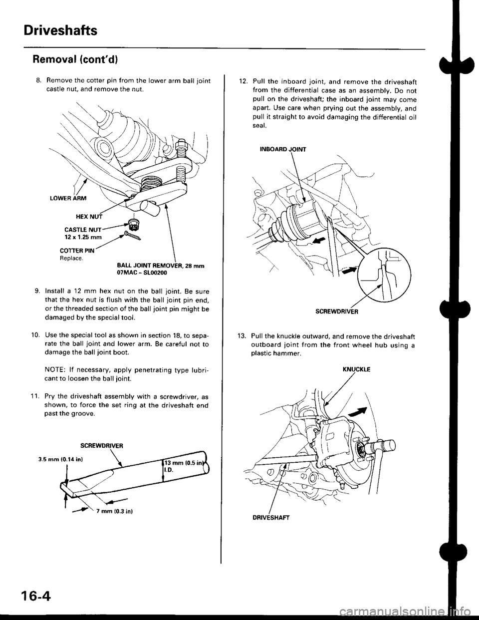
8. Remove the cotter pin from the lawer arm ball joint
castle nut. and remove the nut.
Install a 12 mm hex nut on the ball joint. Be sure
that the hex nut is flush with the ball joint pin end,
or the threaded section of the ball joint pin might be
damaged by the special tool.
Use the special tool as shown in section 18, to sepa-
rate the ball joint and lower arm. Be careful not to
damage the ball joint boot.
NOTE: lf necessary, apply penetrating type lubri,
cant to loosen the ball joint.
Pry the driveshaft assembly with a screwdriver, as
shown, to force the set ring at the driveshaft endpast the groove.
10.
11.
3.5 mm
07MAC - SL00200
SCREWDRIVER
16-4
12. Pull the inboard joint, and remove the driveshaft
from the differential case as an assembly. Do notpull on the driveshaft; the inboard joint may come
apart. Use care when prying out the assembly, andpull it straight to avoid damaging the differential oil
seat.
13. Pull the knuckle outward, and remove the driveshaft
outboard joint from the front wheel hub using aplastic hammer.
SCREWDRIVER
DRIVESHAFT
Page 1052 of 2189
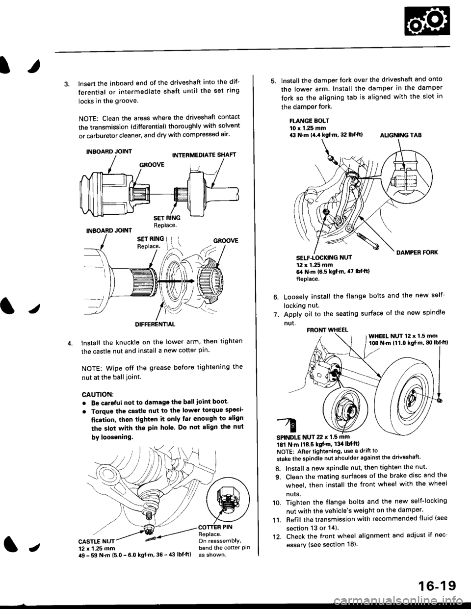
3. lnsert the inboard end of the driveshaft into the dif-
terential or intermediate shaft until the set ring
locks in the groove
NOTE: Clean the areas where the driveshaft contact
the transmission (differential) thoroughly with solvent
or carburetor cleaner, and dry with compressed air'
INBOARD JOINT
INBOARD JOINTReplace.
GROOVE
an
DIFFERENTIAL
lnstall the knuckie on the lower arm. then trghten
the castle nut and install a new cotter pin
NOTE: wipe off the grease before tightening the
nut at the ball ioint.
CAUTION:
. Be careful not to damago the ball ioint boot'
. Torque the castle nut to the lower torque sp€ci-
fication, thsn tighten it only far enough to align
the slot with th€ pin hol6. Do not align the nut
by loosening.
CASTLE NUT12 x 1 .25 mm
COTTER PINReplace.On reassemblY,bend the cotter pinJi$ - 59 N.m 15.0 - 6.0 kgl m,35 - 43 lbf ftl
16-19
5. lnstall the damper tork over the driveshaft and onto
the lower arm. Install the damper in the damper
fork so the aligning tab is aligned with the slot in
the damPer fork.
FLANGE BOLTl0 r 1.25 mmrit N.m t4.a kgf.m, 32 lbf.ft) AIIGN|NG TAB
1.
SELF-LOGKING NUT12 x 1.25 mm6,1N.m 16.5 kgi.m, a7 lbfftl
Replace.
Loosely install the flange bolts and the new self-
locking nut.
Apply oil to the seating surface of the new spindle
nut.
181 N m 118.5 kgt'm, 13il lbt'ftl
NOTE: Aftortightening, use a drift to
stake the spindle nut shoulder against the drivoshaft'
8. Install a new spindle nut, then tighten the nut'
9. Clean the mating surfaces ot the brake disc and the
wheel. then install the front wheel with the wheel
nuts.
10. Tighten the flange bolts and the new self-locking
nut with the vehicle's weight on the damper.
11. Refill the transmission with recommended fluid (see
section 13 or 14).'t2. Check the front wheel alignment and adjust if nec-
essary (see section 18),
FRONT WHEEL
SPINDLE NUT 22 x 1.5 mm
WHEEL NUT 12 x 1.5 mm108 N.m (11.0 kgl'm, g) lbl ftl
Page 1053 of 2189
Intermediate Shaft
Removal
Drain the transmission oil or fluid {see section 13 or
r 4).
Remove the left driveshaft (see page 16-3).
Remove the three dowel bolts.
OOWEL BOLTS'10 x 1.25 mm
Remove the intermediate shaft from the differential.
CAUTION: Hold the intermsdiate shaft horizontal
until it is clear of lhe dilterential to prevent damage
to the differential oil seal.
'1.
2.
3.
INTERMEDIATE SHAFT
16-20
Disassembly
NOTE: Be careful not to damage the metal rings on theintermediate shaft during disassembly.
1. Remove the set ring.
2. Remove the intermediate shaft outer seal from theDeaflng suppon.
3. Remove the external circlip,
Page 1056 of 2189
lnstallation
1. lnsert the intermediate shaft assembly into the dif-
ferential.
CAUTION: Hold the intermodiate shaft horizontal
to prevent damag€ to the difterential oil seal'
NOTE: Clean the areas where the intermediate shaft
contacts the transmission (differential) thoroughly
with solvent or carburetor cleaner, and dry with com-
Dressed air,
2. Install the three dowel bolts, then tighten them'
DOWEL BOLTS10 x 1.25 mm39 N.m {i1.0 kgf'm, 29 lbf'ftl
lz
16-23
Page 1061 of 2189
Steering Gearbox
l.r
Rack Guide Adjustment
NOTE: Perform the rack guide adjustment with the
wheels in the straight ahead position.
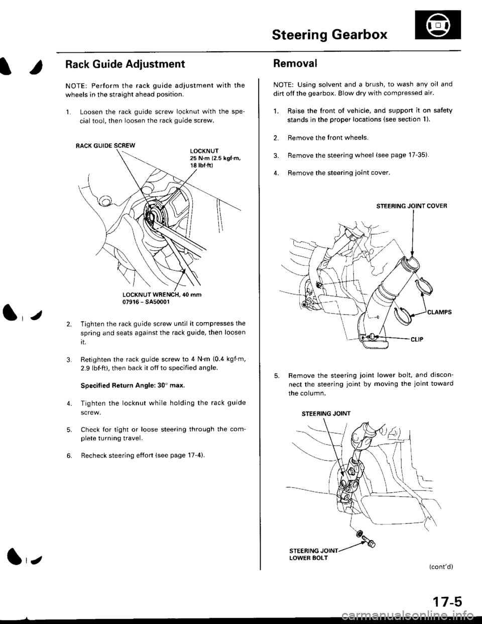
1. Loosen the rack guide screw locknut with the spe-
cial tool, then loosen the rack guide screw.
LOCKNUT WRENCH, 40 mm07916 - SA5000r
Tighten the rack guide screw until it compresses the
spring and seats against the rack guide, then loosen
rt.
Retighten the rack guide screw to 4 N'm (0.4 kgf m,
2.9 lbf.ft), then back it off to specified angle.
Specilied Return Angle: 30' max.
Tighten the locknut while holding the rack guide
Check for tight or loose steering through the com-
plete turning travel.
Recheck steering effort (see page 17-4).
4.
RACK GUIDE SCREW
l,z
Removal
NOTE: Using solvent and a brush, to wash any oil and
dirt off the gearbox. Blow dry with compressed air.
1. Raise the front of vehicle, and support it on satety
stands in the proper locations (see section I ).
2. Remove the front wheels.
3. Remove the steering wheel (see page 17-35).
4. Remove the steering loint cover
Remove the steering joint lower bolt, and discon-
nect the steering joint by moving the joint toward
the column.
(cont'd)
17-5
STEERING JOINT COVER
LOWER BOLT
STEERING JOINT
Page 1074 of 2189
System Description
Steering Pump (cont'dl
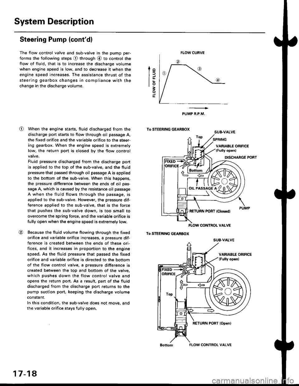
The flow control valve and sub-valve in the pump per-
forms the following steps @ through @ to control the
flow of fluid, that is to increase the discharge volume
when engine speed is low, and to decrease it when the
engine speed increases. The assistance thrust of the
steering gearbox changes in compliance with the
change in the discharge volume.
When the engine starts, fluid discharged from the
discharge port starts to flow through oil passage A,
the fixed orifice and the variable orifice to the steer-
ing gearbox. When the engine speed is extremely
low, the return port is closed by the flow control
Fluid pressure discharged from the discharge port
is applied to the top of the sub-valve, and the fluid
pressure that passed through oil passage A is applied
to the bottom of the sub-valve. When this happens,
the pressure difference between the ends of oil pas-
sage A, which is caused by the resistance oil passage
A when the fluid flows through the passage. is
applied to the sub-valve, However, the pressure dif-
ference applied to the sub-valve. that is the force
that pushes the sub-valve down, is too small to
overcome the spring force, and the variable orifice is
fully open when the engine speed is extremely low.
Because the fluid volume flowing through the fixed
orifice and variable orifice increases, a pressure dif-
terence is created between the ends of these ori-
fices, and it increases in proportion to the engine
speed. As the fluid pressure that passed the fixed
orifice and variable orifice is directed to the bottom
of the flow control valve. a pressure difference is
created between the top and bottom of the valve,
which pushes down the flow control valve and
opens the return port. As a result, pan of the fluid
discharged from the discharge port feturns to the
pump suction port, keeping the discharge volume
constant.
In this condition, the sub-valve does not move. and
the variable orifice stays fully open.
lo
trrtrrlo3
J
o
PUMP R.P.M.
To STEERING GEARBOXSUB.VALVE
To STEEnING GEARBOX
FLOW CURVE
!rs+/f/ffih\
o,,-i^"l^tKzYt)91y ul3Yl
FLOW CONTNOL VALVE
su8-vALvE
ORIFICE
ToP
17-18
FLOW CONTROL VALVE
Page 1075 of 2189
t
To STEERING GEARBOX
To STEERING GEAREOx
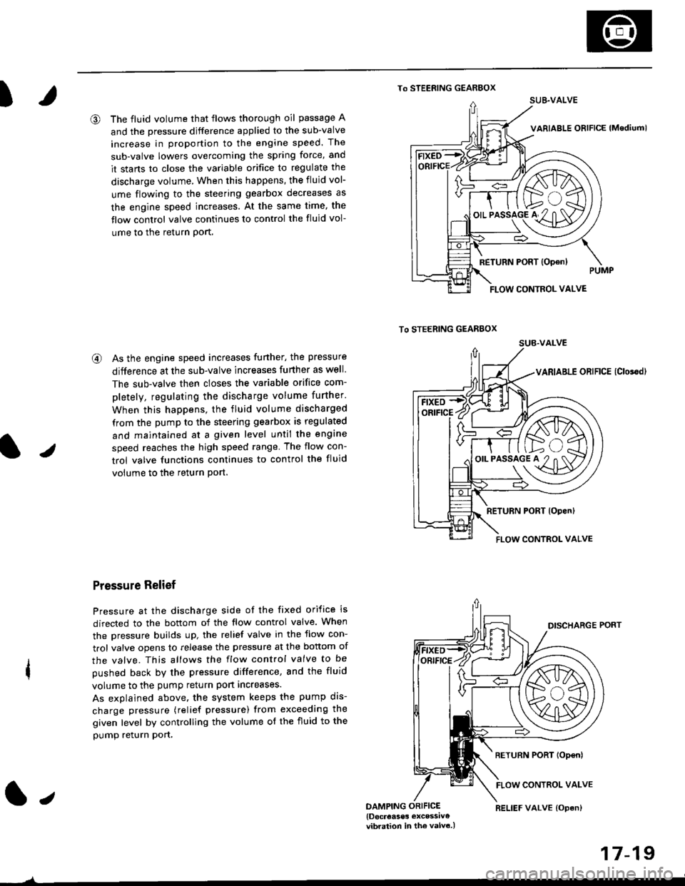
@ The fluid volume that flows thorough oil passage A
and the pressure djfference applied to the sub-valve
increase in proportion to the engine speed. The
sub-valve lowers overcoming the spring force, and
it stans to close the variable orifice to regulate the
discharge volume, When this happens, the fluid vol-
ume flowing to the steering gearbox decreases as
the engine speed increases. At the same time, the
flow control valve continues to control the fluid vol-
ume to the return Port,
@ As the engine speed increases funher, the pressure
difference at the sub-valve increases further as well.
The sub-valve then closes the variable orifice com-
pletely, regulating the discharge volume further.
When this happens, the fluid volume discharged
from the pump to the steering gearbox is regulated
and maintained at a given level until the engine
speed reaches the high speed range The flow con-
trol valve functions continues to control the fluid
volume to the return Port.
Pressure Relief
Pressure at the discharge side of the fixed orifice is
directed to the bottom of the flow control valve. When
the pressure builds up, the relief valve in the flow con-
trol valve opens to release the pressure at the bottom of
the valve. This allows the flow control valve to be
pushed back by the pressure difference, and the fluid
volume to the pump return port increases.
As explained above. the system keeps the pump dis-
charge pressure (relief pressure) from exceeding the
given level by controlling the volume of the fluid to the
pump relurn pon,
1.,DAMPING ORIFICE{Docreases excessiv€vibration in the valv6.)
17-19
)
RELIEF VALVE {Opan)
SUB.VALVE
FLOW CONTROL VALVE
/F ft>..\
'-€/K\A/A
o'.'to"5lo'#2"n af11\D7
FLOW CONTROL VALVE
Page 1081 of 2189
/
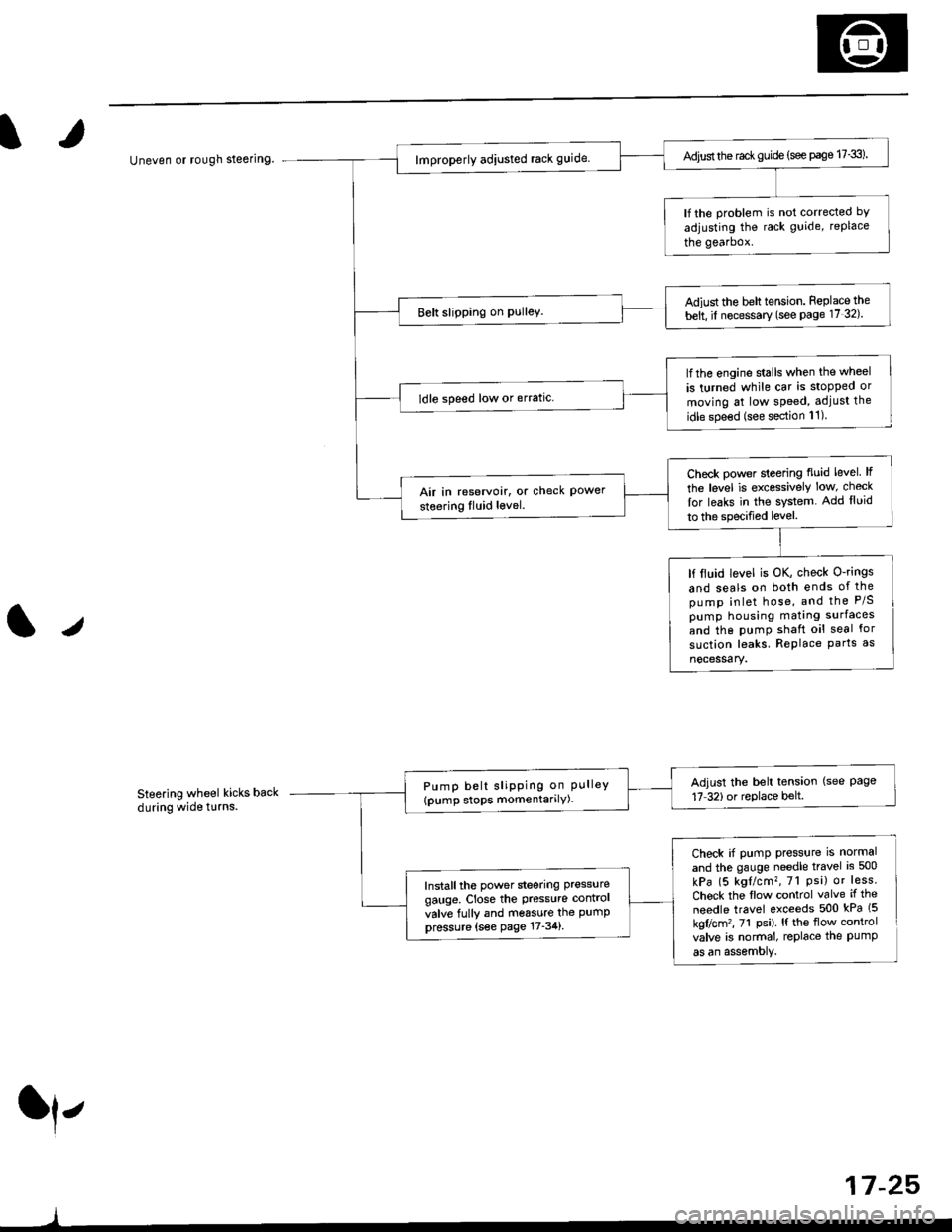
Uneven or rough steering
Steering wheel kicks back
during wide t!rns.
ll,
)
Adjust the rac* guide (see page 17-3).
lf the problem is not corrected bY
adjusting the rack guide, replace
the gearbox.
Adiust the belt tension. Feplace the
belt, il necessary (see Page 17 32).
lfthe engine stalls when the wheel
is turned while car is stopped or
moving at low speed, adjust the
idle spe€d (see section 11)
ldle speed low or erratic.
Check power sleering fluid level lf
the level is excessively low, check
lor leaks in the system. Add lluid
to the specified level.
Air in reservoir, or check Powersteering Iluid level.
lf ltuid level is OK, check O-rings
and seals on both ends of thepump inlet hose, and the P/Spump housing mating surfaces
and the pumP shaft oil seal for
suction leaks. RePlace Parts as
nocessary.
Adjust the belt tension (see Page17 32)or replace belt.Pump belt sliPPing on PLrlleY(pump stops momentarilY)
Check if pump press{rre is normal
and the gauge needle travel is 500
kPa (5 kgl/cm?, 7l Psi) or less.
Chock the flow control valve if the
needle travel exceeds 500 kPa (5
kgflcm'�, 71 Psi). l{ the flow control
valve is normal, replace the PumPas an assemoly.
Install the power steering pressure
gauge, Close the Pressure contrcl
valve fully and m6ssure the PumPpressure {s€e page 17-34}.
17 -25,