1996 HONDA CIVIC Oil
[x] Cancel search: OilPage 676 of 2189

Oil Seals
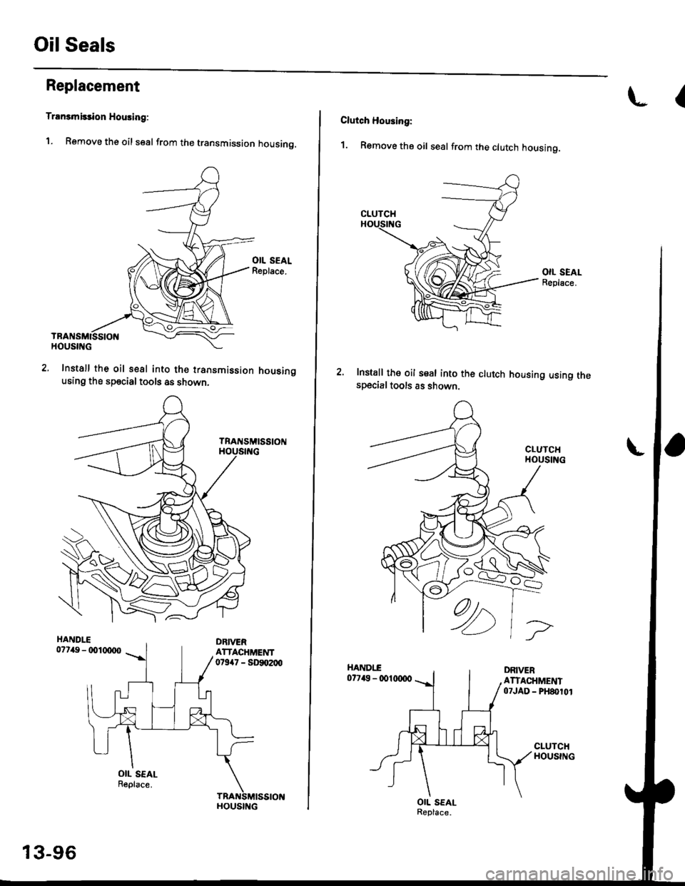
Replacement
Trrn3mirdon Housing:
1. Remove the oil seal from the transmission housing.
Install the oil seal into the transmission housingusing the sp€cial tools as shown,
HANDLE07149 - d)l(xxto
OIL SEALReplace.
HOUSING
13-96
OIL SEALReplace.
{
Clutch Housing:
1. Remove the oil seal from the clutch housing.
OIL SEALReplace.
Install the oil seal into the clutch housing using thespecialtools as shown.
HANDTI0t?a9 - 001o(xto
Page 677 of 2189

Gearshift Mechanism
Overhaul
NOTE:
. Inspect rubber parts for wear and damage when disassembling;
. Install the spring pin and the clip on the change joint as shown'
. Turn the shift rod boot so the hole is facing down as shown'
. Make sure the shift rod boot is installed on the shift rod'
reDlace any worn or damaged Parts.
I x 1.25 mm22 N.m 12.2 kgf.m, 16 lbf.ft)
ffi-:t't:il1ii51i?"'*,
TU
/g3i'51!Exii
V ExrENsroN
EXTENSfON ilr'eol.T
EXTENSION ENDBUSHING
hV\
EXTENSIONWASI{ER B
MOUNT -_.--_-_---
@2'
--1'>=2 -:liT.i'ff"
.o,-.o*&--ffi{---*,
v/,,/ BALL SEAT
8 x 1.25 mm22 N.m 12.2 kgf'm, 16lblftl
,@
EXTENSION ROD
SHIFT ROD
SPRING
END
BOOT
N: g sHrFr LEvER
.*rr"r,o"-tf V-oiliiSi[a
MOUNTING I --::=t SHIFT I"EVERBRAcxEr / €9-l--enr xoloen
8 x 1.2s mm :-,rro""a,ii-ri- ri.z rsr.-, -.Q u
16 tbf.ft) ,,,.
,rar-aoa*,"o "u, / E ,",t.ruaa
Replace.6x1.0mm9.8 N.m ('1.0 kgt'm,7 tbr.ftt
8x22mmSPRING PINReplace.
IIt
@CLIP
9.a-"t't
PIN SHIFT ROD/
ZW
€lt#-,\
HOLE
13-97
Page 679 of 2189

Automatic Transmission
Special Tools ......... .....'."".'-.-.' 14'2
Description .,....................-...... 14-3
power Flow ......,................. 14"6
Elestronic Control System .... . ................'..'.'.. 14-13
Hvdraulic Control .....'......" 1'l-19
Hydraulic F|ow...... .'.'.".'....11-21
Lock-up System '............ ... t/t'33
Electrical System
Component Locations....,.............'......'.............'.,. 14'39
PCM Circuit Diagram
lA/T Control Syst€m: '96 - 98 Models) .........'.. 1/t-40
PCM Tarminal Volt8ge/Measuring Condhions
{'96 - 98 ModeblA/T Control System ............
PCM Circuit Disgram(A/T Conlrol System: '99 - 00 Modsls) '..........' 14-44
PCM Terminal Voltage/Measuring Conditions('99 - 00 Models)A/T Control System ...
Troubleshooting Proceduros ....
Symptom-to-ComPonent Chari
Efectricaf SFiem - '96 - 98 Models '..-.-..."'.'..11-52
Eloqtrical System -'99 - 00 Modols ... .........". 1+54
EleclricatTroubl$hooting ('96 - 98 Models)
Valve Body
Repair .................... ........'.... 14-139
Valve
Assembly
ATF Pump
1,1-1i10
Inspection ...........'.......... 14-141
Main Valvs Body
Disass€mbf y/lnspoction/R.sssembly .'.'.'.'.. -. -. 1 1-1 12
Secondsry Valve BodY
Disa$embfy/lnspoction/Rsassembly ......'.'.'.'. 11-111
Regulator Valve Body
Disa$embly/lnspoction/Rea3sembly ..........'... 14-1{5
Servo Body
Disassombly/lnsp€ction/Reassembly .".'........ 14-146
Lock-up Valv6 Body
Dis$s.mbf y/ln3poction/Rea$embly .'.. -. -..'.'.' 1 1-1 17
Mainsh!ft
Dkassembly/lnep€ction Reassembly ..'...'........ 14'148
Inspoction .............'..........'. l it-149
Countsrshaft
Disa$embly/lnspeqtion/Rea3sembly .......'...'.. 1a-l51
Dba$ombly/Re$s.mblY11-152
til-46
I rl-48
Troubleshooting Flowcharts
Electrical Troubleshooting ('9!t - 00 Models)
Troublsshooting Flowchart3
Lock-up Control Solenoid vslvo A/B AssemblY
RePlacoment
Shift Cont.ol Solenoid Valve A/B A3sembly
Inspestion
Ona-way Clutch
Disassembh/lrupoction/Rca$embly .. "'........ l4-155
Clutch
lllustlttcd Ind.x {A48A, B4RA Transmlssion) ..' 14-156
tustr.tod Index (MrnA Transmi$ionl ............ til-158
...................... 14-153
L
14-56
1+81'
14-105
1+105
Replacoment ......
Mainshaft/Countorshaft Spo€d Sonsors
Replacemsnt ......'."'........... lit'108
Hydraulic System
Symptom-to-Componeni Chart
Hydraulic Sydemr+109
t4-113
1+116
11-117
Rea$emblY
14-106 Difforrr ial
llhdraied Index........ t4-156
B.ckhrh ln3poction. 14-167
Boaring Roplacemont..-..........11-167
..... 14-108 Diftrrsniial Carrior Repl8cemeni .'.-.............'...' lil-168
Oil Sall Romovalt4-t 59
Oil Soal ln3tallstion/Sidc Clearance'......'.....'... 1'l'169
Torqua Convertcr Housing Boarings
Mlin3haft Besring/Oil Scal Roplac.ment ."..'.. lil-172
Counio6hatt Betring R.plscem.nt ..'...... ....... 14-173
Test.....,......14-106
14-107
14-160
11-162
11-171
11-175
Replacement
Test .....,.,..........
Road Te3t
Linear Solenoid AsssmblY
Stall Speed
lllustrated Indax
Transmission/End Cover'. ....
Transmission Hou3ing,.............'.'......'....""..-.-.. 11-128
Torque Conve.ter Housing/Valvo Body ........... 14-130
End Cover
14-itB Park Stop
1+119 In3pection/Adiustmsnt...'......'.'............'...."""'14-175
Transmbgion
Reassombly
11-122 Torquo Convertet/Drivr Plsie ............'.'............'.. . l4-182
Transmission
11.726 Inrtallation
Tranlmission Housing Boarings
Msinsh.ft /CounteEhaft Bearings
B!pltcomgnt
Rcvo.3s ldlor Gear
lnrtallation
Cooler Flushing ..
Shift Cabls
Test
Fluid Level
Checkin9 .........."..'.'.....
Changing
Pressure Testing
Transmission
Transmission
Rgmoval ..
lil-176
.'..........'.'.'..... 1'l-183
.... lil-187
11-132Adiustmont
RemovaUlnttallation1,1-190
lit-191Transmisgion Housing
Removal ... '.'...... ......'..... 14-l3il
Tolque Convgrter Housing/valvs Body
Rsmoval .........,...... ............. 14-136
Valve CaDs
Description .......'................. t 4'138
Shift lndicator Panel
Adiu3tmant ..'.................. 14-192
ATF Coolor Hoses
Connection ..,............,.,....... l'l-192
Shift Lever .,........
Page 680 of 2189

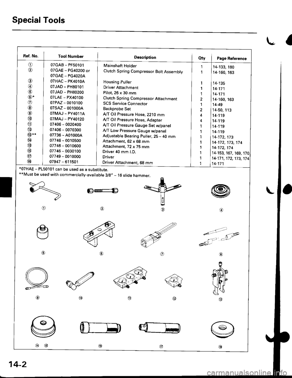
Special Tools
l.- a
Ref. No. Tool Number
o,6'\
€)
@)
@-
@
@
o
@
@
@
@..
@
@
@
@
@
07GAB - PF50101
07GAE - PG40200 or
OTGAE - PG4O2OA
07HAC - PK4010A
07JAD - PH80101
07JAD - PH80200
07LAE - PX40100
07PM - 0010100
07sM - 0010004
OTMAJ - PY4O1 1A
07MAJ - PY40120
07406 - 0020400
07406 - 0070300
07736 - A010004
07746 - 0010500
07746 - 0010600
07746 - 0030100
07749 - 0010000
07947 - 611501
Mainshaft Holder
Clutch Spring Compressor Bolt Assembly
Housing Puller
Driver Attachment
Pilot, 26 x 30 mm
Clutch Spring Compresso. Attachmenr
SCS Service Connector
Backprobe Set
IVT Oil Pressure Hose, 2210 mmAy'T Oil Pressure Hose, Adapter
Ay'T Oil Pressure Gauge Set dpanelA,/T Low Pressure Gauge WpanelAdjustable Bearing Pulter, 25 - 40 mmAftachment, 62 x 68 mm
Aftachment, 72 x 75 mmDriver 40 mm l.D.
Driver
Driver Attachment, 68 mm
I
1
1
1
I
1,l
'l
1
I
1
1
14-133, 180
14-160, 163
14-135
14-171
14-'�t7'l
14-160, 163
14-49
14-50, 113
r4-119
14- 1 19
14-119'14-1 19
14-172,173
14-172,'t73,114
14-172,174
14-153, 167. 169, 170
1+17 1 , 17 2, 173, 17
14-'t7'l
4
w
@o
*07HAE - P150101 can be used as a substitute.**Must be used with commercially-available 3/8,, _ 16 slide
E-E
@
@@
hammer.
=k
lalg
€)
ry
o
e
@
o
----a\\<-t-'- /\26
@@
@@@
aL
14-2
Page 783 of 2189

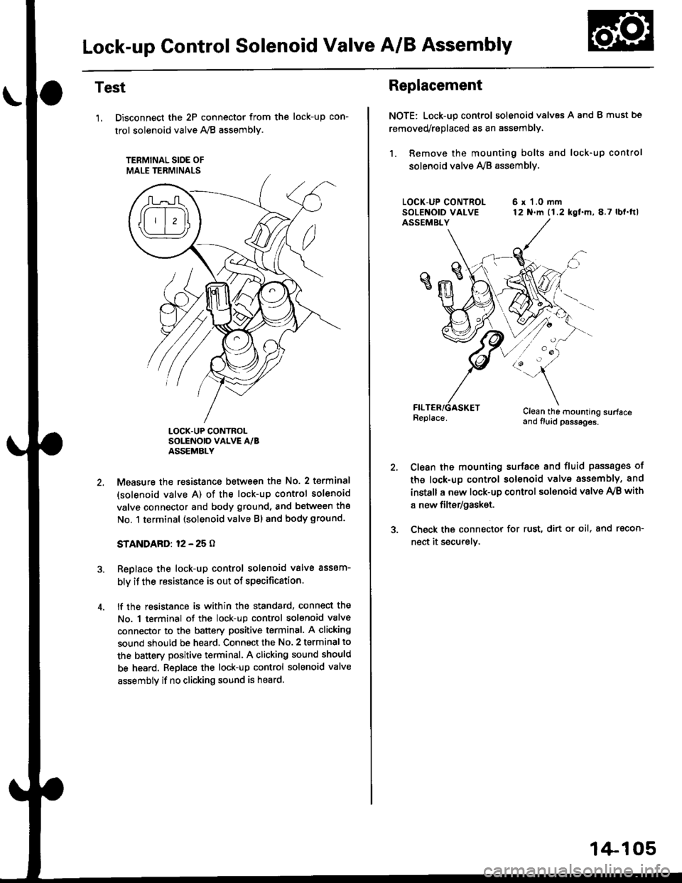
Lock-up Gontrol Solenoid Valve A/B Assembly
Test
'1, Disconnect the 2P connector from the
trol solenoid valve 1y'8 assembly.
TERMINAL SIOE OF
MALE TERMINALS
tocK-up con-
LOCK.UP CONTROLSOLENOID VALVE A/BASSEMBLY
Measure the resistance between the No. 2 terminal
(solenoid valve A) of the lock-up control solenoid
valve connector and body ground, and between the
No. 1 terminal (solenoid valve Bl and body ground.
STANDARD: 12 - 25 O
Replace the lock-up control solenoid valve assem-
bly if the resistance is out of specification.
lf the resistance is within the standard, connect the
No. 1 terminal of the lock-up control solenoid valve
connector to the battery positive terminal. A clicking
sound should be heard. Connsct the No. 2 terminal to
the battery positive terminal. A clicking sound should
be heard. Replace the lock-up control solenoid valve
assembly if no clicking sound is heard.
Replacement
NOTE: Lock-up control solenoid valves A and I must bs
removed/replaced as an assembly.
1. Remove the mounting bolts and lock-up control
solenoid valve Ay'B assemblv.
6 r 1.0 mm12 N.m (1.2 kgf.m,8.7 lbl.ftl
/:'-
Clean the mounting surfaceand fluid psssages.
Clean the mounting surface and fluid passages of
th6 lock-up control solenoid valve assembly, and
instsll a new lock-up control sol€noid valve Ay'B with
a new filtsr/gask€t.
Check the connector for rust, dirt or oil, and racon-
nect it securely.
1+105
Page 784 of 2189

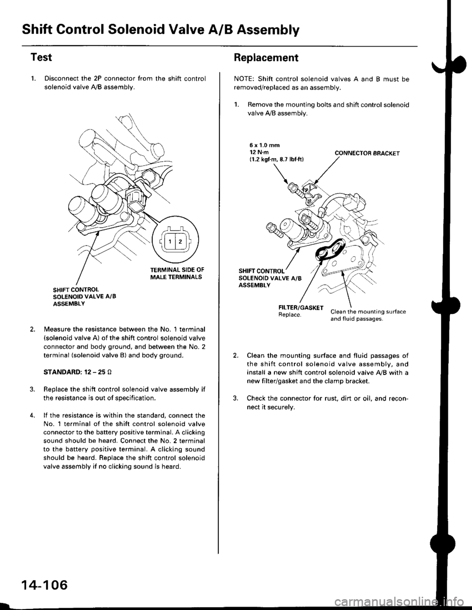
Shift Control Solenoid Valve A/B Assembly
Test
1. Disconnect the 2P connector from the shift control
solenoid valve A,/B assemblv.
SHIFT CONTROLSOLENOID VALVE A/B
ASSEMBLY
N4easure the resistance between the No. 1 terminal(solenoid valve A) of the shift control solenoid valve
connector and body ground, and between the No. 2
terminal (solenoid valve B) and body ground.
STANDARD: 12 - 25 O
Replace the shift control solenoid valve assembly if
the resistance is out of specification,
lf the resistance is within the standard, connect the
No. 1 te.minal of the shift control solenoid valve
connector to the battery positive terminal. A clicking
sound should be heard. Connect the No. 2 terminal
to the battery positive terminal. A clicking sound
should be heard. Replace the shift control solenoid
valve assembly if no clicking sound is heard.
14-106
Replacement
NOTE: Shift control solenoid valves A and B must be
removed/replaced as an assembly.
1. Remove the mounting bolts and shift control solenoid
valve A,/B assembly.
5xL0mm12 N.m(1.2 kgf.m,8.7 lbf.ft)CONNECTOR BRACKET
FILTER/GASKETBeplace.Clean the mounting surfaceand fluid passages.
Clean the mounting surface and fluid passages of
the shift control solenoid valve assembly, and
install a new shift control solenoid valve Ay'B with a
new filter/gasket and the clamp bracket.
Check the connector for rust. dirt or oil. and recon-
nect it securelv,
Page 786 of 2189

Mai nshaft/Cou ntershaft
Linear Solenoid AssemblySpeed Sensors
Replacement
1. Remove the mounting bolts and the linear solenoid
assemory.
Clean the mounting surfaceand flu id passages.
6x1.0mm12 N.m 11.2 kgl m,8.7 tbf.ftl
@
@
GASKET
Clean the mounting surface and fluid passage of the
linear solenoid assembly and transmission housing.
Install a new linear solenoid assembly with a new
gasl(et.
NOTE; Do not pinch the gasket when installing the
linear solenoid; make sure that the gasket is installedproperly in the mounting groove of the linear sole-
noid.
Check the linear solenoid connector for rust, dirt or
oil, and connect it securely,
LINEARSOLENOIDASSEMELY
I
14-108
Replacement
't.
6x128.7
Remove the 6 mm bolt and the countershaft speed
sensor from the right side cover.
COUNTERSI{AFTSPEED SENSOR
O.RINGReplace.
MAINSHAFTSPEEDSENSOR
MAINSHAFT SPEEDSENSOB WAS}IER(D16Y7 enginel
6x1.0mm12 N.m (1.2 kgf m,8.7 tbf.ft)
1.0 mmN.m (1.2 kgf.m,rbf ft)
\\
/,
%/E:)
Remove the 6 mm bolt and the mainshaft sDeed
sensor from the transmission housino.
Replace the O-ring with a new one before installing
the countershaft speed sensor or th€ mainshaft speed
sensor.
NOTE: Installthe mainshaft speed sensor washer on
the mainshaft speed sensor. The mainshaft speed
sensor washer is used on models with the D'|6Y7
engine.
Page 797 of 2189

Pressure Testing
@I While testing, be caroful of th€ rotating front wheels.
. Make sure lifts, iacks, and satoty stands are placod properly (see section 1)'
CAUTION:
. Beforo iesting, be sure the transmission fluid is tilled to tho proper level'
. Warm up tho engine before testing'
1. Raise the vehicle (see section 1).
2. Warm up the engine, then stop the engine and connect a tachometer'
3. Connect the oil pressure gauges to each inspection hole.
TOROUE: 18 N.m (1.8 kgf'm, 13 lbnft)
cAUTloN: connact the oil pressuro gauges securely; be suro not to allow dust and other foreign Parlicles to entel
the inspestion holos'
A/T OIL PRESSURE GAUGESET w/PANEL07t06 - 0020400
A/T LOW PRESSURE GAUGE
SET WPANEL07406 - 0070300
A/T OIL PRESSURE HOSEADAPTER07Mru - PY0120(4 requiJedl
A/T OIL PBESSURE HOSE
2210 mmOTMAJ - PY4{)llA
14 roquircdl
Start the engine, and measure the respective ptessure as follows'
a Line Pressure
. 1st Clutch Pressure
. 2nd,3rd and 4th Clutch Pressure
Install a new washer and the sealing bolt in the inspection hole. and tighten to the specified torque'
TOROUE: l8 N.m (1.8 kgf'm,13lbf'ft)
NOTE: Do not reuse old sealing washers; always replace washers'
(cont'd)
14-119