1996 HONDA CIVIC Reset srs
[x] Cancel search: Reset srsPage 1555 of 2189
Under-dash Fuse/RelaY Box
Removal/lnstallation
SRS components are located in this area. Review lhe
SRS component locations, precautions, and procedures
in the SRS section (24) before performing repairs or ser-
vice.
Removal:
1. Make sure you have the anti-lheft code for the radio
then write down the frequencies lor the radio's pre-
set buttons ('99 - 00 modelsl.
2. Disconnect the battery negative cable. then discon
nect the positive cable, and wait at least three min
utes,
3. Disconnect the airbag connectors (see section 24)'
4. Remove the driver's dashboard lower cover and
knee bolster (see section 20)
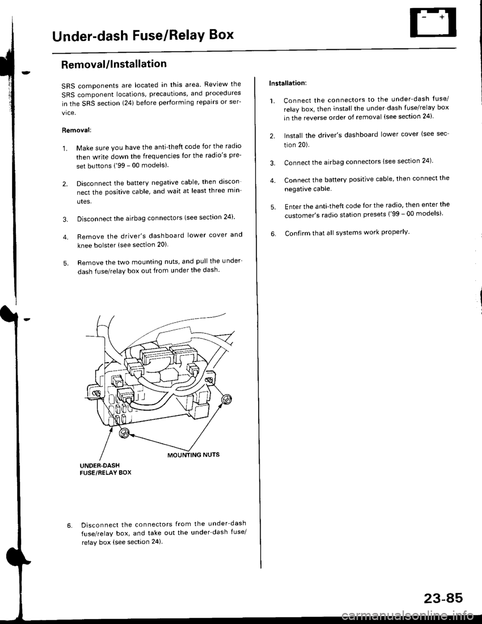
5. Remove the two mounting nuts, and pull the under
dash fuse/relay box out from under the dash'
6. Disconnect the connectors from the under-dash
fuse/relay box, and take out the under-dash fuse/
relay box (see section 24).
lnstallation:
1. Connect the connectors to the under-dash tuse/
relay box, then install the under dash fuse/relay box
in the reverse order of removal (see section 24)'
2. Install the driver's dashboard lower cover (see sec
tion 20).
3. Connect the airbag connectors {see section 24)
4. Connect the battery positive cable, then connect the
negative cable.
5. Enter the anti-theft code lor the radio, then enter the
customer's radio station presets ('99 - 00 models)'
6. Confirm that all sYstems work properly'
23-45
Page 1559 of 2189
lgnition Switch
4.
Test
SRS components are located in this area Review the
SRS component locations. precautions. and procedures
in the SRS section {24} before performing repairs or ser-
1. i/ake sure you have the anti-theft code for the
radio, then write down the frequencies for the
radio's preset buttons ('99 - 00 models).
2. Disconnect the battery negative cable.
3. Remove the driver's dashboard lower cover and
knee bolster (see section 20).
Disconnect the 5P connector from the under dash
fuse/relay box and the 7P connector from the main
wire harness.
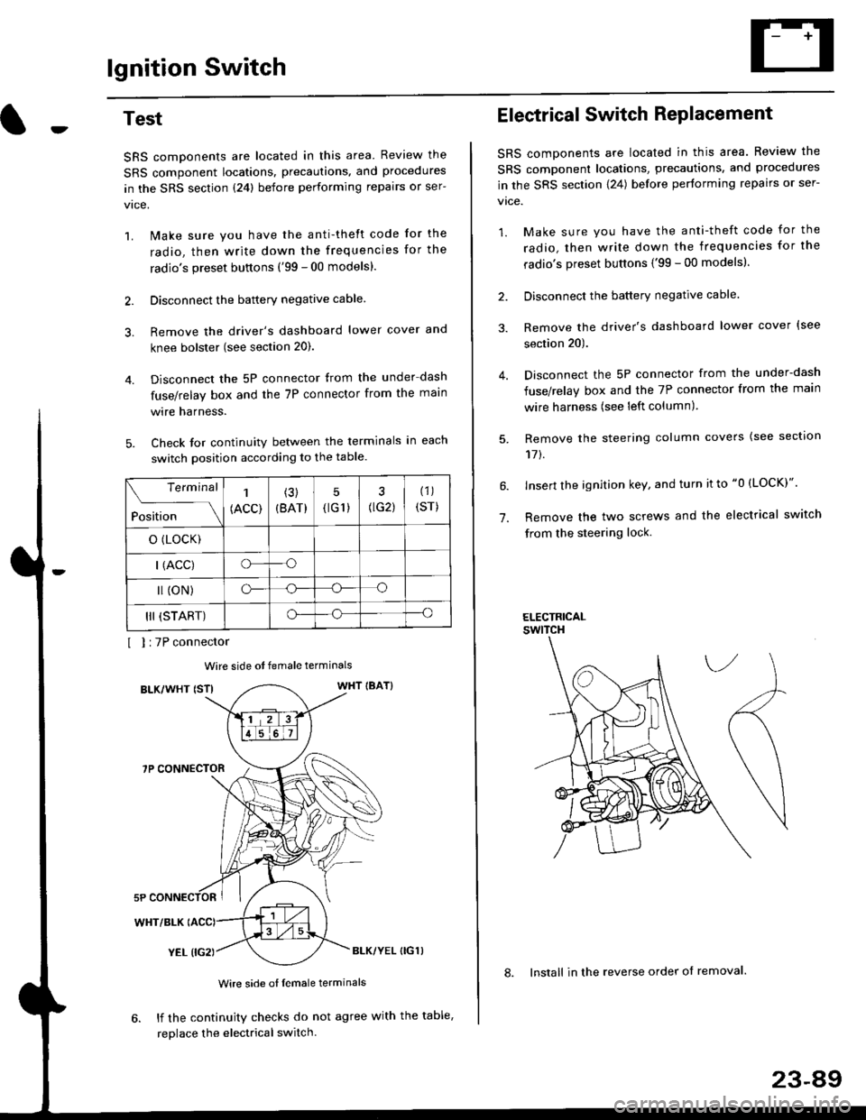
Check for continuity between the terminals in each
switch position according to the table.
I I :7P connector
Wire side ot female terminals
BLK/WHT {STIWHT IBAT}
7P CONNECTOR
WHT/BLK
YEL (IG2}BLK/YEL {IG1)
Wire side of female terminals
6. lf the continuity checks do not agree with the table,
replace the electrical switch.
Terminal
Position
1
(ACC)
(3)
(BAT)
5
{tG1) G2)
(1)
(sr)
o (LocK)
| (ACC)o--o
l (oN)o-o
III (START)o--o
1.
Electrical Switch RePlacement
SRS components are located in this area. Review the
SRS component locations, precautions, and procedures
in the SRS section \24) belore performing repairs or ser-
vtce.
1. Make sure you have the anti-theft code for the
radio, then write down the frequencies for the
radio's preset buttons {'99 - 00 modelsl.
2. Disconnect the battery negatlve cable.
3. Remove the driver's dashboard lower cover {see
section 20).
Disconnect the 5P connector from the under-dash
fuse/relay box and the 7P connector from the main
wire harness (see left column).
Remove the steering column covers {see section
11t.
lnsert the ignition key, and turn it to "0 {LOCK)".
Remove the two screws and the electrical switch
from the steering lock.
ELECTRICALswtTcH
8. Install in the reverse order of removal.
23-a9
Page 1560 of 2189
lgnition Switch
Steering Lock Replacement
SRS components are located in this area. Review theSRS component locations. precautions, and procedures
in the SRS section (24) before performing repairs or ser-vtce.
Remove:
LMake sure you have the anti-theft code for theradio, then wire down the frequencies for theradio's preset buttons ('99 - 00 models).
Disconnect the battery negative cable.
Remove the driver's dashboard lower cover andknee bolster (see section 20).
Disconnect the 5P connector from the under-dash
fuse/relay box and the 7P connector from the mainwire harness (see previous page).
Remove the steering column covers, then removethe mounting bolts and nuts from the steering col-umn (see section l7).
Lower the steering column assembly,
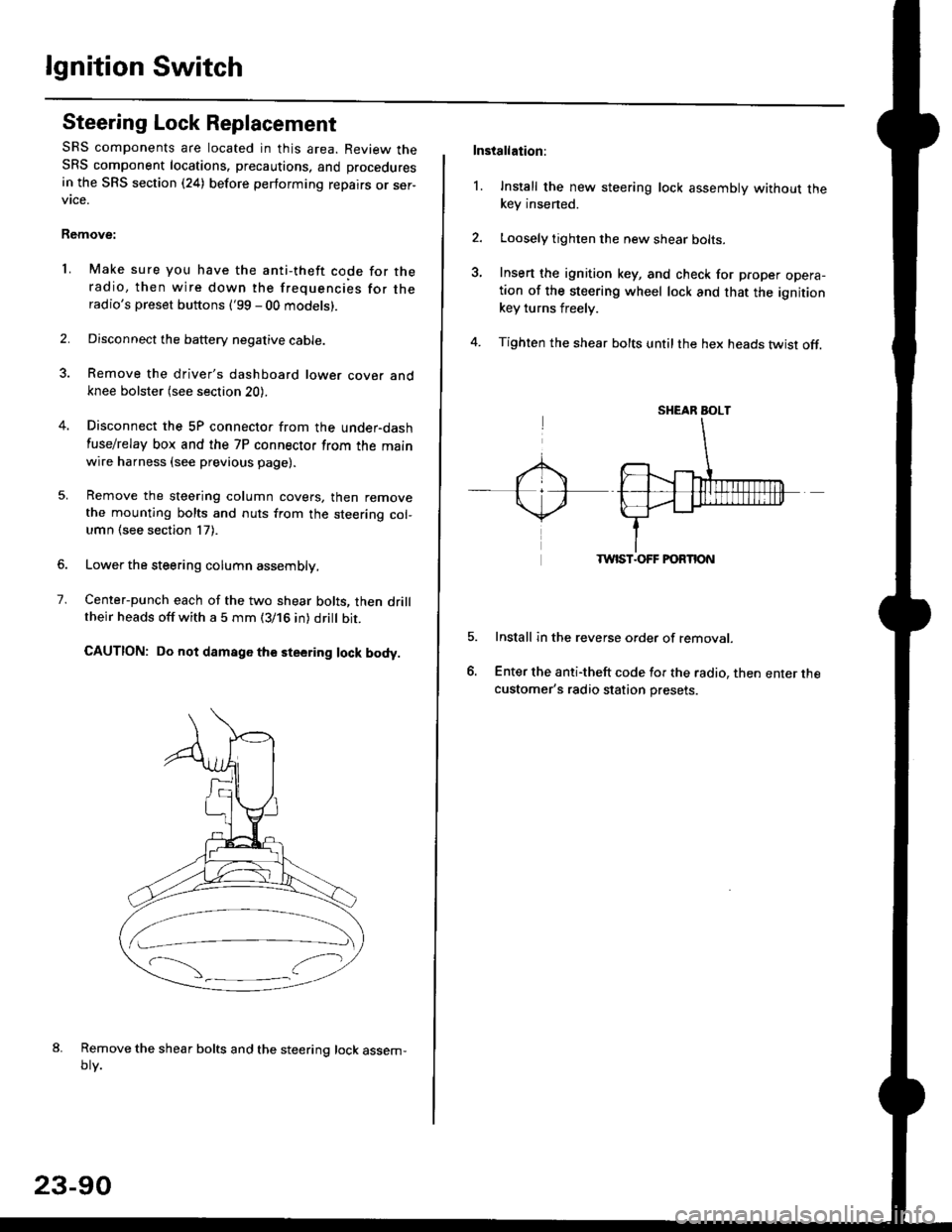
Center-punch each of the two shear bolts, then drilltheir heads off with a 5 mm (3/16 in) dritt bit.
CAUTION: Do not damago the steering lock body.
Remove the shear bolts and the steering lock assem,oty.
2.
1.
23-90
Installation:
l. Install the new steering lock assembly without thekey insened.
Loosely tighten the new shear bolts-
Insert the ignition key, and check for proper opera-tion of the steering wheel lock and that the ignitionkey turns freely.
Tighten the shear bolts untilthe hex heads twist off.
TWIST.OFF FORTION
Install in the reverse order of removar.
Enter the anti-theft code for the radio, then enter thecustomer's radio station presets.
sr{€aR SroLT
Page 1669 of 2189
Switch Test
lMake sure you have the anti-theft code for the
radio, then write down the frequencies for the
radio's preset buttons ('99 - 00 models).
Disconnect the battery negative cable, then disconnect
the positive cable, and wait at least three minutes.
Disconnect the driver's airbag connector (see sec-
tion 24).
Remove the driver's dashboard lower cover (see
section 20).
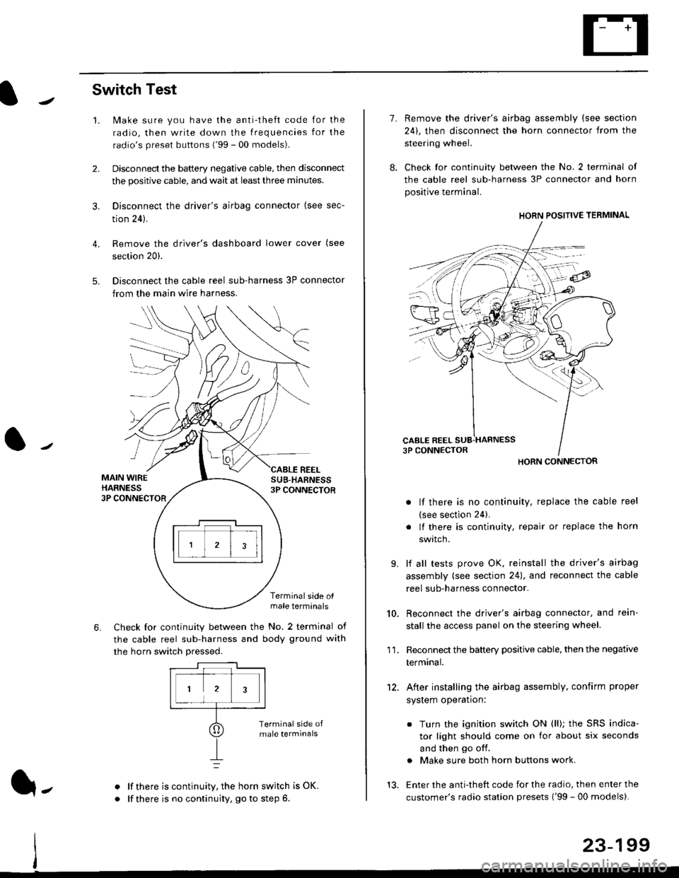
Disconnect the cable reel sub-harness 3P connector
from the main wire harness.
2.
3.
4.
5.
1.
MAIN WIREHARNESS3P CONNECTOR
SUB-HABNESS3P CONNECTOR
REEL
6.
Terminalside olmale terminals
Check for continuity between the No. 2 terminal of
the cable reel sub-harness and body ground with
the horn switch pressed.
alf there is continuity, the horn switch is OK.
lf there is no continuity, go to step 6l-
-\
1.
8.
10.
'I 1.
9.
Remove the driver's airbag assembly (see section
24), then disconnect the horn connector from the
steering wheel.
Check for continuity between the No. 2 terminal of
the cable reel sub-harness 3P connector and horn
positive terminal.
lf there is no continuity, replace the cable reel
(see section 24).
lf there is continuity, repair or replace the horn
swtlcn,
lf all tests prove OK, reinstall the driver's airbag
assembly (see section 24), and reconnect the cable
reel sub-harness connector.
Reconnect the driver's airbag connector, and rein-
stall the access panel on the steering wheel.
Reconnect the battery positive cable, then the negative
termtnar.
After installing the airbag assembly, confirm proper
system operation:
12.
Turn the ignition switch ON (ll); the SRS indica-
tor light should come on for about six seconds
and then go off.
Make sure both horn buttons work.
13. Enter the anti-theft code for the radio, then enter the
customer's radio station presets ('99 - 00 models).
HORN CONNECTOR
23-199
Page 1752 of 2189
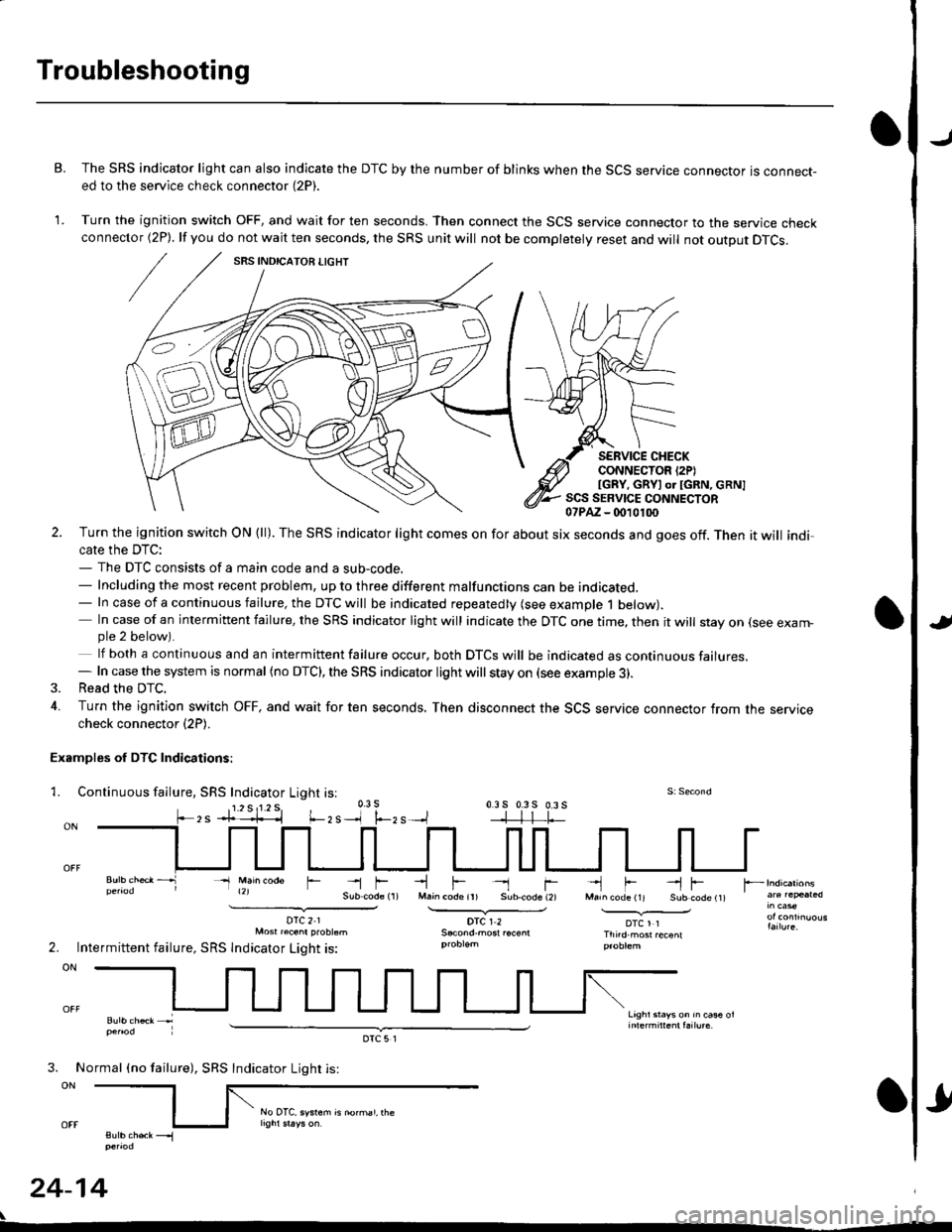
Troubleshooting
J
J
B. The SRS indicator light can also indicate the DTC by the number of blinks when the SCS service connector is connect-ed to the service check connector (2P).
1. Turn the ignition switch OFF, and wait for ten seconds. Then connect the SCS service connector to the service checkconnector (2P). lf you do not wait ten seconds, the SRS unit will not be completely reset and will not output DTCS.
SERVICE CHECKCONNECTOR {2PIIGRY, GRYI or IGRN, cRN]SCS SERVICE CONNECTOR07PAZ - (m10100
l.-zs
2. Turn the ignition switch ON (ll). The SRS indicator light comes on for about six seconds and goes off. Then it will indi,cate the DTC:- The DTC consists of a main code and a sub-code.- Including the most recent problem, up to three different malfunctions can be indicated.- In case of a continuous failure, the DTC will be indicated repeatedly (see example 1 below).- In case of an intermittent failure, the SRS indicator light will indicate the DTC one time, then it will stay on (see exam-ple 2 below).
lf both a continuous and an intermittent failure occur, both DTCS will be indicated as continuous failures.- In case the system is normal (no DTC), the SRS indicator light will stay on (see example 3).3. Read the DTC.
4. Turn the ignition switch OFF, and wait for ten seconds. Then disconnect the SCS service connector from the servicecheck connector (2P).
Examples of DTC Indications:
1. Continuous fallure, SRS Indicator Light isl
- Main @de
DTC21Mosr raenr probtsm
Intermittent failure, SRS lndicator Light is:
-lF- rM.in code ir) Sub.code (2)
DTCI2
-'l F --l FMarn code (11 Sub code t1t
DTCl1Thnd.most recenl
Lrghr srays on rn ca* ol
r --
2.
3. No
ON
sutb chek __.1penod
24-14
rmal (no failure), SRS
DTC5l
Indicator Light is:
rl
No OTC, system is norhal, rhe