Page 848 of 2189

Differential
Oil Seal Installation/Side Clearance (cont'd)
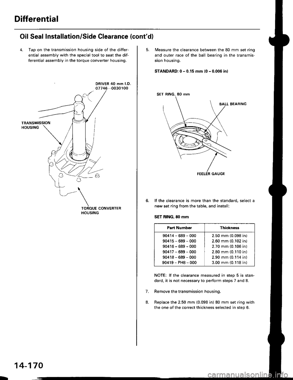
4. Tap on the transmission housing side of the differ-
ential assembly with the special tool to seat the dif-
ferential assembly in the torque converter housing.
DRIVER 40 mm l.D.
L
14-170
5. N4easure the clearance between the 80 mm set ring
and outer race of the ball bearino in the transmis-
sion housing.
STANDARD: 0 - 0.15 mm (0 - 0.006 inl
SET RING, 80 mm
BALL BEARING
lf the clearance is more than the standard, select a
new set ring from the table, and install:
SET RING, 80 mm
NOTE: lf the clearance measured in step 5 is stan-
dard, it is not necessary to perform steps 7 and 8.
Remove the transmission housing.
Replace the 2.50 mm (0.098 in) 80 mm set ring with
the one of the correct thickness selected in step 6.
7.
Part NumberThickness
90414-689-000
904r5-689-000
90416-689-000
90417-689-000
90418-689-000
904r9-PH8-000
2.50 mm (0.098 in)
2.60 mm {0.102 in)
2.70 mm {0.106 in)
2.80 mm (0.110 in)
2.90 mm (0.114 in)
3.00 mm (0.118 in)
Page 849 of 2189
9. lnstall the new oil seal flush with the transmission
housjng using the special tools as shown
DRIVER077i(} - 0010000
PILOT.26x30mm07JAO - PH80200
DRIVER ATTACHMENT, 68 mm
079i17-6110501
10. lnstall the new oil seal flush with the torque con-
verter housing using the specialtools as shown
DRIVER07749 - 0010000
14-171
Page 850 of 2189
Torque Converter Housing Bearings
Mainshaft Bearing/Oil Seal Replacement
1.Remove the mainshaft bearing and oil seal using
the special tools as shown.
3/8"16 SLIOE HAMMER
ADJUSTAELE BEARINGPULLER, 25 - ilo mm07736 - A01000a
L
14-172
2. Drive in the new mainshaft bearing until it bottomsin the housing using the special tools as shown.
DRIVER077€ - 0010000
lnstall the new oil seal flush with the housing using
the special tools as shown.
DBIVER07749 - 0o l0(xt0
ATTACHMENT,72x75 mfi07746 - 001 0600
Page 871 of 2189

Continuously Variable Transmission (CVTI
Special Tools ................ 14-194
Description .................... 14-195
Clutches/Reverse Brake/Planetary
Gear/Pulleys .......... 14-198
power Flow ..............,..... 14-200
Electronic Control SYstem(,96 - 98 Modets) ......14-203
Electronic Control System
('99 - oo Models) " 14-205
Hydraulic Control '....... 14-208
Hydraulic Flow .'..-.....'... '14-212
Park Mechanism .....-...'.' 14-222
Eleqtrical Systom
Component Locations'96 - 98 Models """"""' 14-224,99 - 00 Modets ............. 14-225
TCM Circuit Diagram ('96 - 98 Models) ............. 14-226
TCM Terminal Voltage/Measuring Condiiions ('96 - 98 Models) '.... 14-228
PcM Circuit Oiaqram{A/T Control System: '99 - 00 Models} ...--.... 14-230
PCM Terminal Voltage/Measuring Conditions('99 - 00 Models)
A/4 Control System .'.'...14-232
Troubleshooting Procedures ... . .... .....',........."' '14-234
Symptom-to-ComPonent Chart
Electrical System - '96 - 98 Models ......'..... '14-234
Electrical System -'99 - 00 Models ..'....-..-. '11-210
Electrical Troubleshooting
Troubleshooting Flowcharts('96 - 98 Models) """'11-242
Troubleshooting Flowchart
('99 - 0O Modets) ...... 14-265
Linear Solenoids/lnhibitor Solenoid
Test ......................... . ...... 14-29f
Drive Pulley/Driven Pulley/Secondary Gear
Shaft Speed Sensors
Replacement .........'...... .14-292
Start Clutch Control
Start Clutch Calibration Procedure ....... ....,. 14-293
Hydraulic SYstem
Symptom-to-ComPonent Chart
Hydraulic System '.'.......14-294
Road Test ............................ 14-296
Stall Speed
Test......................... ...... 14-294
Fluid Level
Checking/Changing ....... 14-299
Pressure Testing ................. 14-300
Lower Valve BodY AssemblY
Replacement ..........,... 14-302
ATF Filter
Removal/lnstallation ..... 14-303
Transmission
Transmission
Removal ........... . 14-304
lllustrated Index
Transmission/Lower Valve BodY
Assembly ................. 14-308
Transmission Housing/Flywheel Housing ... 14-310
End Cover/f ntermediate Housing ..........'.'.... 14-312
Transmission Housing/Lower Valve Body Assembly
Removal ..........'.... .. " 14-314
Transmission Housing/Flywhesl Housing
Removal ................. ........ 1+316
End Cover/lntermediate Housing
14-318Removal .........,...............
Manual Valve Body
Disassembly/lnspection/Reassemblv .'.'.'..... 1 4-320
Forward Clutch
lltustrated Index ........................................ 14-321
Disassemblv .................. 14-322
Reassemblv , ,, . ',','......14-324
Secondary Gear Shaft
25 x 35 mm Thrust Shim Selection ..'.'....-... 14-324
Differential
lllustrated lndex ...,.....................,.,...-.-.-...'... 14-329
Backlash Inspection .-....14-329
Bearing Replacement ......'........'....'... ....'... 14-330
Differential Carrier Replacement ........'........ 14-330
Oil Seal Removal ........... 14-331
Oil Seal Installation/Side Clearance ....... . . 14-331
Flywheel Housing Input Shaft Oil Seal
Replacement .....,.... ...'.'.. 14-333
Transmission Housing Bearings
Driven Pulley Shaft Bearing
Replacenient ...................'. . ...................'.. 14-334
Secondary Gear Shaft Bearing
Reolacbment ...................... . .......... . ........ 14-335
Flywheel Housing Beating
Secondary Gear Shaft BearingReo1acement..................,........................... 14-335
Ring Gear Bearing
Replacement......... ........ 14-336
Control Shaft Assembly
Removal/lnstallation ....................'........... 14-336
Transmission
Reassembly .................. 14-338
Flywheel/Drive Plate .. . ...... . ...... ... . ....-.....'.'...14-341
Transmission
lnstalation ..................... 14-348
Cooler Flushing .'......... 14-352
shift cable
Removal/lnstallation....'........." """ 14-354
Adjustment .......'........ 14-355
Shift Lever ........................,. 14'356
Shift Indicator Panel
Adjustment ................ 14-357
ATF Cooler/Hoses
lnsta llation ......,,...... .... 14-357
Page 872 of 2189

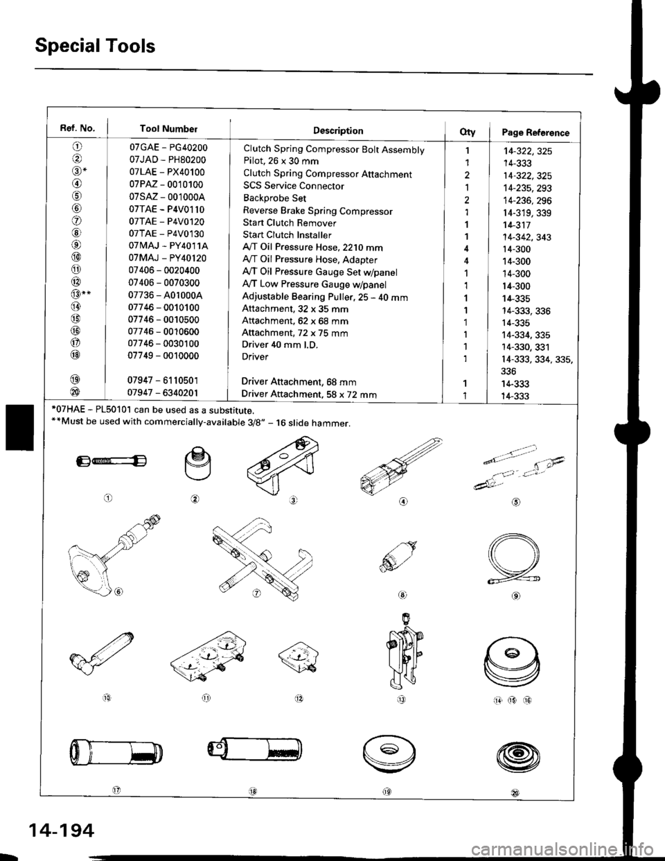
Special Tools
Ref. No. I Tool Number
o
@alr *
@
o
@6l
@
o
@
@-"
@
@
@
o
@
07GAE - PG40200
07JAD - PH80200
07LAE - PX40100
07PM - 0010100
07sM- 0010004
07TAE - P4V01l0
07TAE - P4V0120
07TAE - P4V0130
07 tvlAJ - PY4011A
07MAJ - PY40l20
07406 - 0020400
07406 - 0070300
07736 - A0r 0004
07746 - 0010100
07746 - 0010500
07746 - 0010600
07746 - 0030100
07749 - 0010000
07947 - 6110501
01947 - 6340201
Clutch Spring Compressor Bolt AssemblyPilot. 26 x 30 mm
Clutch Spring Compressor Attachment
SCS Service Connector
Backprobe Set
Reverse Brake Spring Compressor
Stan Clutch Remover
Stan Clutch Installer
A/T Oil Pressure Hose,2210 mmAy'T Oil Pressure Hose, Adapter
Ay'T Oil Pressure cauge Set WpanelAy'T Low Pressure Gauge w/panel
Adjustable Bearing Puller, 25 - 40 mmAttachment, 32 x 35 mm
Attachment, 62 x 68 mm
Attachment, 72 x 75 mm
Driver 40 mm l.D.
Driver
Driver Aftachment, 68 mm
Driver Attachment, 58 x 72 mm
I
1
2
Ia,l
1
1
1,1
1
1'1
I
1
1
't4-322,325
14-333
14-322,325't4-235,293
14-236, 296
r4-319,339't 4-311
14-342,343't4-300
14-300
14-300
14-300
14-335
14-333, 336
14-335
14-334, 335
14-330, 331
14-333, 334, 335,
336
14-333
14-333*07HAE - PL5010l can be used as a substitute.**Must be used with commercially-available 3/8.,- 16 slide hammer.
E*E
o
e
@
>.'.- -t-'- t'\;4
e'o
1:,'Jt*
dAt:-
io(313
@
@
@
@18l
aio
@
IR
L
14-194
Page 882 of 2189
Description
Electronic Control System ('gG - 98 Modelsl (cont'dl
Circuit Diagram and Terminal Locations
GNITIONSWITCN
Pri - Pt coNTnoLLrN ns0LtN0t0
SIAiT CLUTCH CONTSOLLINEAFSOLENOID
sHtFT CONmOILINIAftSOLENOID
BFAXELIGHT
PAS|(ING 8MI(E SWITCH
i\c-...............- +B
i\--------.--_ rcr
: MAP(PBIg s61
E rtDiRxo
g TM8
scs
123518I1011't22578910
14172023261213t4t6171820
D
14-204
Page 903 of 2189
TCM Circuit Diagram ('96 - 98 Modelsl
UNDEN. HOOD FUSE]RELAY BOX
UNDER OASHFUSE/RELAY 80X
No. 52 1l5A)
No.4l l80A) No.47 (7.5A)
To t 2v lG1sToP sw T HBR( sw- - rur
A/T GEAR POSITIONINDICATOR
IGNITION COIL
Y
I
i
I
IBI-U
rsl
PARKINGBRAKEswrTcH
V
I
I
I
I
IGRN/REO
,t, I
l
I
IGnN,4,vHT
LT GRN
ELKi BI-U
RED
GRN/BLK
NoTEi if :ro 5V
T :To t2v
cRN ---l F----- GnN
Bru -J F------ 61U
8LK
II
Tl
G401G404
,o IJ'^A'
14-226
Page 915 of 2189

Symptom-to-Component Chart
Electrical System -'96 - 98 Models
*: The DTC in parentheses is the code @ indicator light indicates when the Data Link Connector is connected to the HondaPGM Tester.
DTC*O Indicator
LightMILDetection ltemPage
P1790
(3)BlinksONThrottle position sensor14-242
P179'l
(4)BlinksONVehicle speed sensor14-243
P1705
(5)BlinksONAy'T gear position switch (short to groundl't 4-244
P1706
(6)OFFONA/T gear position switch {open)14-246
P0725
(11)BlinksONlgnition coil14-248
P1793
112lBlinksONManifold absolute pressure sensor14-249
P 1870(30)BlinksONShift control linear solenoid14-250
P'1873
(311BlinksONPH-PL control linear solenoid14-25'l
P1879(32)BlinksONStart clutch control linear sotenoid14-252
P1882BlinksONInhibitor solenoid14-253
P1885
(34)BlinksONDrive pulley speed sensor1l-Zb4
P1886(35)BlinksONDriven pulley speed sensor14-255
P1888
(36)BlinksONSecondary gear shaft speed sensor14-256
T to55
(37)BlinksONECM or TCM14-257
P1890
l42lBlinksONShift control system14-259
P1891
(43)BlinksONStart clutch control svstem14-260
14-23a