1996 HONDA CIVIC Oil
[x] Cancel search: OilPage 1175 of 2189
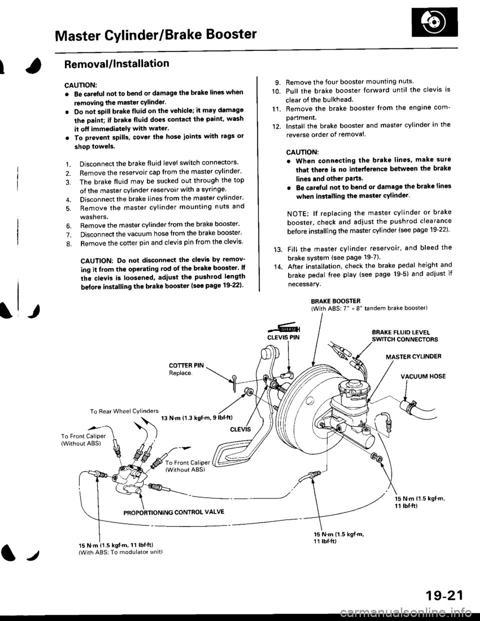
Master Cylinder/Brake Booster
IRemovaUlnstallation
CAUTION:
. Be care{ul nol to bend or damage the brake lines when
rsmoving the mastsr cYlinder.
. Do not soill brakefluid on the vehicle; it may damage
the paint; if brake fluid does contact the paint, wssh
it off immediatelY with water'
. To prevent spill3, cover the hose ioints with rags or
shop towels.
9. Remove the four booster mountlng nuts
10. Pull the brake booster forward until the clevis is
clear of the bulkhead.
11. Remove the brake booster from the engine com-
panmenr.'12. Install the brake booster and master cylinder in the
reverse order of removal.
CAUTION:
. When connecting the brake lines. make sure
that there is no inte erence between the brake
lines and oth6r Parts.
r Be careful not to bend or damage the brake lines
when installing the master cylinder.
NOTE: lf replacing the master cylinder or brake
booster, check and adiust the pushrod clearance
be{ore installing the master cylinder (see page 19-221'
Fill the master cylinder reservoir, and bleed the
brake svstem (see Page 19-7).
After installation. check the brake pedal height and
brake pedal tree play (see page l9-5) and adjust if
necessary.
BRAKE BOOSTER(With ABS: 7" + 8" tandem brake booster)
BRAKE FLUIO LEVELSWITCH CONNECTORS
MASTER CYLINDER
VACUUM HOSE
1.
2.
3,
5.
Disconnect the brake fluid level switch connectors'
Remove the reservoir cap from the master cylinder'
The brake fluid may be sucked out through the top
of the master cylinder reservoir with a syrlnge.
Disconnect the brake lines from the master cylinder'
Remove the master cylinder mounting nuts and
washers.
\l/
6. Remove the master cylinder from the brake booster'
7. Disconnect the vacuum hose trom the brake booster'
8. Remove the cotter pin and clevis pin from the clevis'
CAUTION: Do not disconnect the clevb by remov-
ing it from the operating rod of the brako booster' lf
the clevis is loosened, adiust the pushrod length
before installing th€ brake booster (see page 19-221'
COTTER PINReplace.
To Rear Wheel Cylinders
14.
-6.4CLEVIS PIN
To Front Caliper(Without ABS)$
t'N't'ttrnt'-''
To Front CaliperlWithout ABSi
PBOPORTIONING CONTROL VALVE
15 N.m {1.5 kgl m,11 tbtft)
15 N.m {1.5 kgif.m, 11 lbtft}(With ABS: To modulator unit)lr
19-21
Page 1185 of 2189
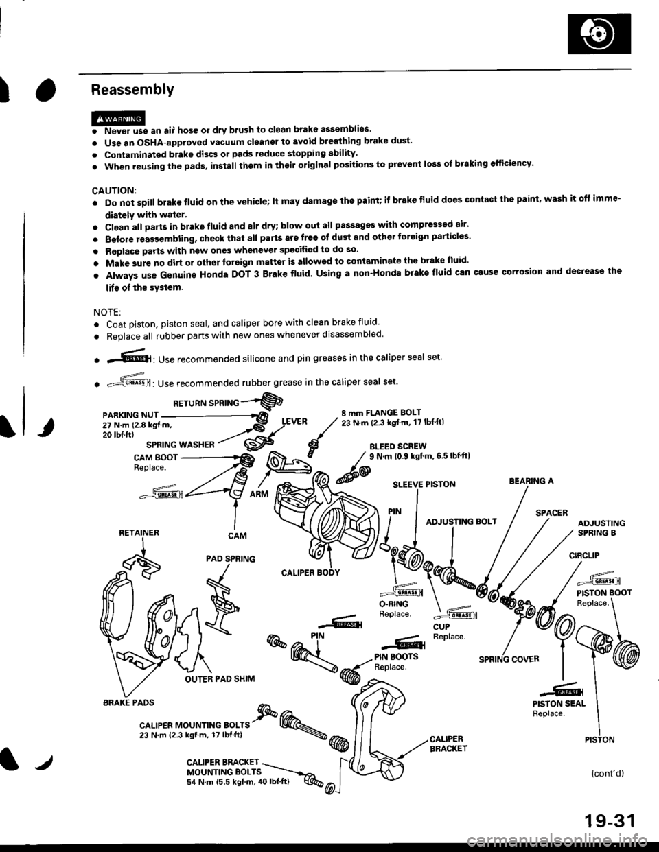
IReassembly
HP* "n ",, hos6 or drv brush to ctoan brake assemblies.
o Use an OSHA-approved vacuum cleanel to avoid brealhing brake dust'
. Contaminated brake discs or pads reduce stopping sbility.
. When reusing the pads, in3tall thom in thoil original positions to prevent loss of braking efficiency'
CAUTION:
. Do not soill brake fluid on the vehicle; lt may damage lhe paint; if brake fluid does contacl the paint' wash it oft imme-
diately with water.
. Cl€an all Darts in brake fluid and air dry; blow out all passagss with comPressed air'
. Belore rsas3embling, check that all parts ars free ot du3t and othor tor€ign particles'
. Replace parts with new ones whenever spscifiod to do so.
o Make sur€ no dirt or othor foreign matter is allowed to contaminate the brake tluid'
. Always use Genuine Honda DOT 3 Brake fluid. Using a non-Honda brake fluid can Gtuse corrosion and decrease the
lif€ of ths system.
NOTE:
. Coat piston, piston seal, and caliper bore with clean brake fluid
. Replace all rubber parts with new ones whenever disassembled.
o .-'{@]: Use recommended silicone and pin greases in the caliper seal set.
. -ffi,Use recommended rubber grease in the caliper seal set.
RETuRN sPRTNG -"'9
8 mm FLANGE BOLT23 N.m (2.3 kgt'm, 17 lbf ftl
BLEED SCREW
@
9 N.m (0.9 kgtm,6.5lbf'ft|
CUP
=^.
PISTON BOOT
(cont'd)
19-31
BEARING A
PAO SPNING
F
\
OUTER PAD SHIM
r--- Replace..ffiPIN BOOTSReplace.
-61
@@-t-.
"l-r,r., "or"'*o " orr" I @.,23 N.m {2.3 kgtm, 17lbf.ftl \@
PISTON SEALReplace.
CALIPEBBRACKET
iiilji:ll;;
__X.,,..".^
BRAKE PAOS
PISTON
l/CALIPER BMCKET \MOUNTINGEOLTS ----.-,o,
54 N.m (5.5 kgf.m, 40lbl.ft) q%
Page 1192 of 2189
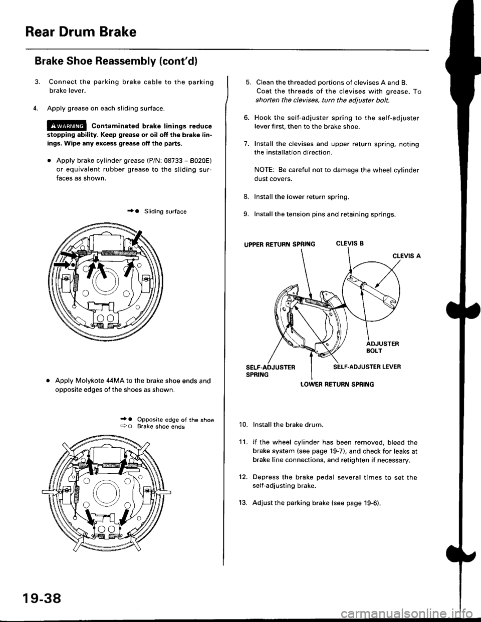
Rear Drum Brake
Brake Shoe Reassembly {cont'dl
Connect the parking brake cable to the parking
brake lever.
Apply grease on each sliding surface.
!@ contaminated brake linings reduce
stopping ability. Keep grease or oil off the blake lin-
ings. Wipe any excess grease off the parts,
. Apply brake cylinder grease {P/N: 08733 - 8020E)
or equivalent rubber grease to the sliding sur-
faces as shown.
+a Sliding surlace
Apply Molykote 44MA to the brake shoe ends and
opposite edges ofthe shoes as shown.
_' o Opposite edge of the shoe+O Brake shoe ends
19-38
13.
5. Clean the threaded portions of clevises A and B.
Coat the threads of the clevises with grease. To
shoften the clevises, tun the adjuster bolt.
6. Hook the self-adjuster spring to the self-adjuster
lever first, then to the brake shoe
7. Install the clevises and upper return spring. noting
the installation direction.
NOTE: Be careful not to damage the wheel cylinder
dust covers,
8. Install the lower return spring.
9. Install the tension pins and retaining springs.
uppER RETURT{ SpRtNG CLEVIS B
CLEVIS A
Installthe brake drum.
lf the wheel cylinder has been removed, bleed the
brake system (see page 19-7), and check for leaks at
brake line connections, and retighten if necessary.
Depress the brake pedal several times to set the
self-adjusting brake.
Adjust the parking brake (see page 19-6).
't0.
11.
12.
LOWER RETURN SPRING
Page 1202 of 2189
L
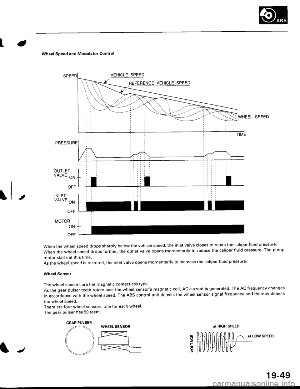
Wheel Soeed and Modulator Contlo
t
OUTLETVALVE ON
OFF
INLETVALVE ON
OFF
t\,40ToR
ON
OFF
when the wheel speed drops sharply below the vehicle speed, the inlet valve closes to retain the caliper fluid pressure
When the wheel speed drops further, the outlet valve opens momentarily to reduce the caliper fluid pressure. The pump
motor starts at this time.
As the wheel speed is restored, the inlet valve opens momentarily to increase the caliper fluid pressure.
Wheel SensoJ
The wheel sensors are the magnetic contactless type
As the gear pulser teeth rotate past the wheel sensor's magnetic coil, AC current is generated The AC frequency changes
in accordance with the wheel speed. The ABS control unit detects the wheel sensor signal frequency and thereby detects
the wheel speed.
There are four wheel sensors, one for each wheel
The gear pulser has 50 teeth.
EEL SPEED
at LOW SPEEDgl
=o
GEAR PULSEBWHEEL SENSOBat HIGH SPEED
/
19-49
Page 1259 of 2189
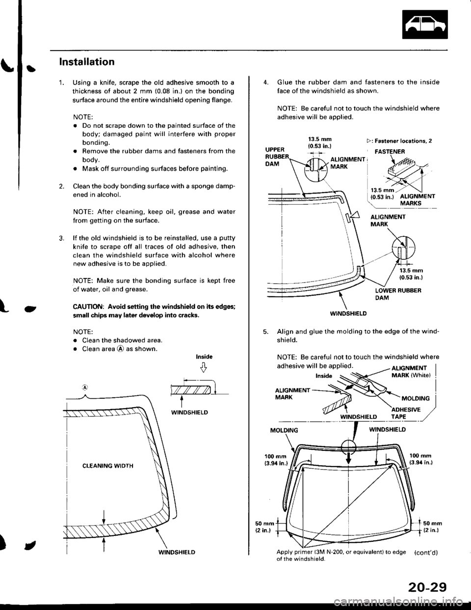
tInstallation
Using a knife, scrape the old adhesive smooth to a
thickness of about 2 mm (0.08 in.) on the bonding
surface around the entire windshield opening flange.
NOTE:
. Do not scrape down to the painted surface of the
body; damaged paint will interfere with proper
bonding.
. Remove the rubber dams and tasteners from the
body.
. Mask off surrounding surfaces before painting.
Clean the body bonding surface with a sponge damp-
ened in alcohol.
NOTE: After cleaning, keep oil, grease and water
from getting on the surface.
lf the old windshield is to be reinstalled, use a putty
knife to scrape off all traces of old adhesive, then
clean the windshield surface with alcohol where
new adhesive is to be applied.
NOTE: Make sure the bonding surface is kept free
of water, oil and grease.
CAUTION: Avoid setting the windshield on its edges;
small chips may later deyelop into cracks.
NOTE:
. Clean the shadowed area.
o Clean area @ as shown.
lnside
&
'1.
2.
3.
Ct
a4)
)
WINDSHIELD
JWINDSHIELD
20-29
Glue the rubber dam and fasteners to the inside
face of the windshield as shown.
NOTE: Be careful not to touch the windshield where
adhesive will be applied.
ALIGNMENTMABK
13.5 mm(0.53 in.)
LOWER RUBBERDAM
WINOSHI€LD
5. Align and glue the molding to the edge of the wind-
shield.
NOTE: Be caretul not to touch the windshield where
>: Faslener localions, 2
FASTENER
ALTGNMENT, -oMARK
MOLOINGWINDSHIELO
100 mm{3.94 in.l
Apply primer (3M N'200, or equivalent) to edSe (cont'd)of the windshield.
Page 1263 of 2189
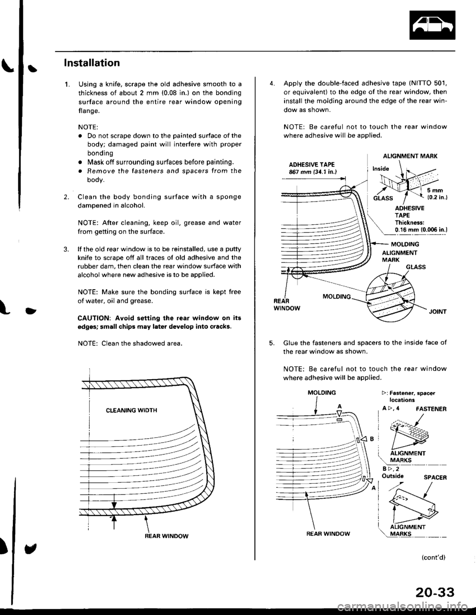
Ilnstallation
Using a knife, scrape the old adhesive smooth to a
thickness of about 2 mm (0.08 in.) on the bonding
surface around the entire rear window opening
flange.
NOTE:
. Do not scrape down to the painted surface of the
body; damaged paint will interfere with proper
bonding
o Mask off surrounding surfaces before painting.
. Remove the fasteners and spacers from the
oooy.
Clean the body bonding surface with a sponge
dampened in alcohol.
NOTE: After cleaning, keep oil. grease and water
from getting on the surface.
lf the old rear window is to be reinstalled, use a putty
knife to scrape off all traces of old adhesive and the
rubber dam, then clean the rear window surface with
alcohol where new adhesive is to be applied.
NOTE: Make sure the bonding surface is kept free
of water, oil and grease.
CAUTION: Avoid setting the rear window on its
edges; small chips may later develop into cracks.
NOTE: Clean the shadowed area.
1.
2.
)
)
REAR WINDOW
4. Apply the double-faced adhesive tape (NITTO 501,
or equivalent) to the edge of the rear window, then
install the molding around the edge of the rear win-
dow as shown.
NOTE: Be careful not to touch the rear window
where adhesive will be applied.
ADHESIVE TAPE867 mm 134. I in.)
5mm{0.2 in.}
ADHESIVETAPEThickness:0.16 mm (0.006 in.l
GLASS
MOLDING
wtNoow
Glue the fasteners and spacers to the inside face of
the rear window as shown.
NOTE; Be careful not to touch the fear window
where adhesive will be applied.
5.
MOLDING
ALIGNMENTMARK
T ALIGNMENT
!
aRKsa >,2Outside
>:Fa3l€ner, spacerlocations
A >, 4 FASTENER
(:r:^#-
ry
I liGrtrrrrertrr\..!44llc-''' - -
SPACER
(cont'd)
20-33
ALIGNMENT MARK
REAR WINOOW
MOLOING
Page 1266 of 2189
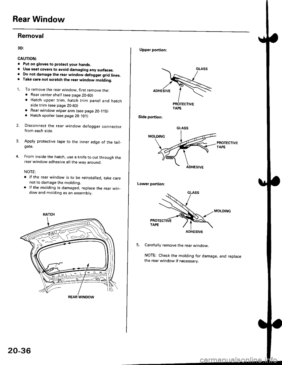
Rear Window
Removal
3D:
CAUTION:
. Put on gloves to ptotect your hands.. Us€ seat cove6 to avoid damaging any surfaces.. Do not damage the rear window defogger grid lines.. Take carg nol scratch the terr window molding.
'1. To remove the rear window, firsr remove the:. Rear center shelf (see page 20-60). Hatch upper trim, hatch trim panel and hatchside trim (see page 20-63)
2.
. Rear window wiper arm (see page 2O-115). Hatch spoiler (see page 20 101)
Disconnect the rear window defogger connectorfrom each side.
Apply protective tape to the inner edge of the tail_gate.
From inside the hatch, use a knife to cut through therear window adhesive all the way around.
NOTE:
. lf the rear window is to be reinstalled, take carenot to damage the molding.. lf the molding is damaged, replace the rear win_dow and molding as an assembly.
HATCH
ffi#
REAR WINOOW
20-36
Upper portioni
TAPE
Side portion:
Lower portion;
Carefully remove the rear window.
NOTE; Check the molding for damage, and replacethe rear window if necessary.
GLASS
ADHESIVE
Page 1267 of 2189
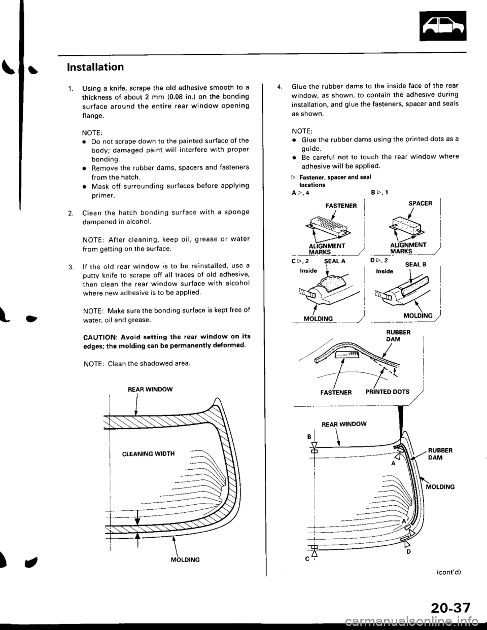
tlnstallation
'1.
3.
Using a knife, scrape the old adhesive smooth to a
thickness of about 2 mm (0.08 in.) on the bonding
surface around the entire rear window opening
flange.
NOTE:
. Do not scrape down to the painted surface ol the
body; damaged paint will interfere with proper
bonding.
a Remove the rubber dams, spacers and fasteners
from the hatch.
. Mask off surrounding surfaces before applying
primer.
Clean the hatch bonding surface with a sponge
dampened in alcohol.
NOTE: After cleaning, keep oil, grease or water
from getting on the surface.
lf the old rear window is to be reinstalled, use a
putty knife to scrape off all traces of old adhesive,
then clean the rear window surface with alcohol
where new adhesive is to be applied.
NOTE; Make sure the bonding surface is kept free of
water, oil and grease.
CAUTION: Avoid setting the rear window on its
edges; the molding can be permanently deformed.
NOTE: Clean the shadowed area
2.
O
)
REAR WINDOW
4. Glue the rubber dams to the inside face of the rear
window, as shown, to contain the adhesive during
installation, and glue the fasteners, spacer and seals
as shown.
NOTE:
. Glue the rubber dams using the printed dots as a
g u ide.
. Be careful not to touch the rear window where
adhesive will be aPPlied
>r Fastener, spacor and seallocations
A>,4B>, 1
SPACER
D> '2 'EAL B'W
/l
si
o.\6fif,", j
ryt48rq _ _ ,,/
-\l
19Pry/
FASTENER PRINTED DOTS
REAR WINDOW
MOLOING
(cont'd)
20-37
FASTENER
"-*^1
wAL.IGNMENT ]IIARKS _ _,/C>,2 SEAL A