Page 1421 of 2189

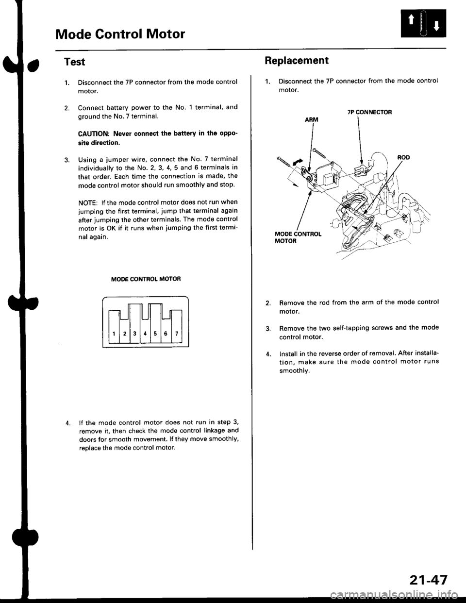
Mode Control Motor
2.
Test
1.
4.
Disconnect the 7P connector from the mode control
motor.
Connect battery power to the No, 1 terminal, and
ground the No.7 terminal,
CAUTION: Never connecl the battery in iho oppo-
site direction.
Using a jumper wire, connect the No. 7 terminal
individually to the No. 2,3, 4,5 and 6 terminals in
that order. Each time the connection is made, the
mode control motor should run smoothly and stop.
NOTE: lf the mode control motor does not run when
jumping the first terminal, jump that terminal again
after jumping the other terminals. The mode control
motor is OK if it runs when jumping the first termi-
nal again.
MODE CONTROL MOTOR
lf the mode control motor does not run in step 3,
remove it. then check the mode control linkage and
doors for smooth movement. lf they move smoothly,
reolace the mode control motor,
Replacement
1. Disconnect the 7P connector from the mode control
motor,
Remove the rod from the arm of the mode control
motor.
Remove the tyvo self-tapping screws and the mode
control motor.
lnstall in the reverse order of removal. After installa'
tion, make sure the mode control motor runs
smoothly.
7P CONNECTOR
21-47
Page 1422 of 2189

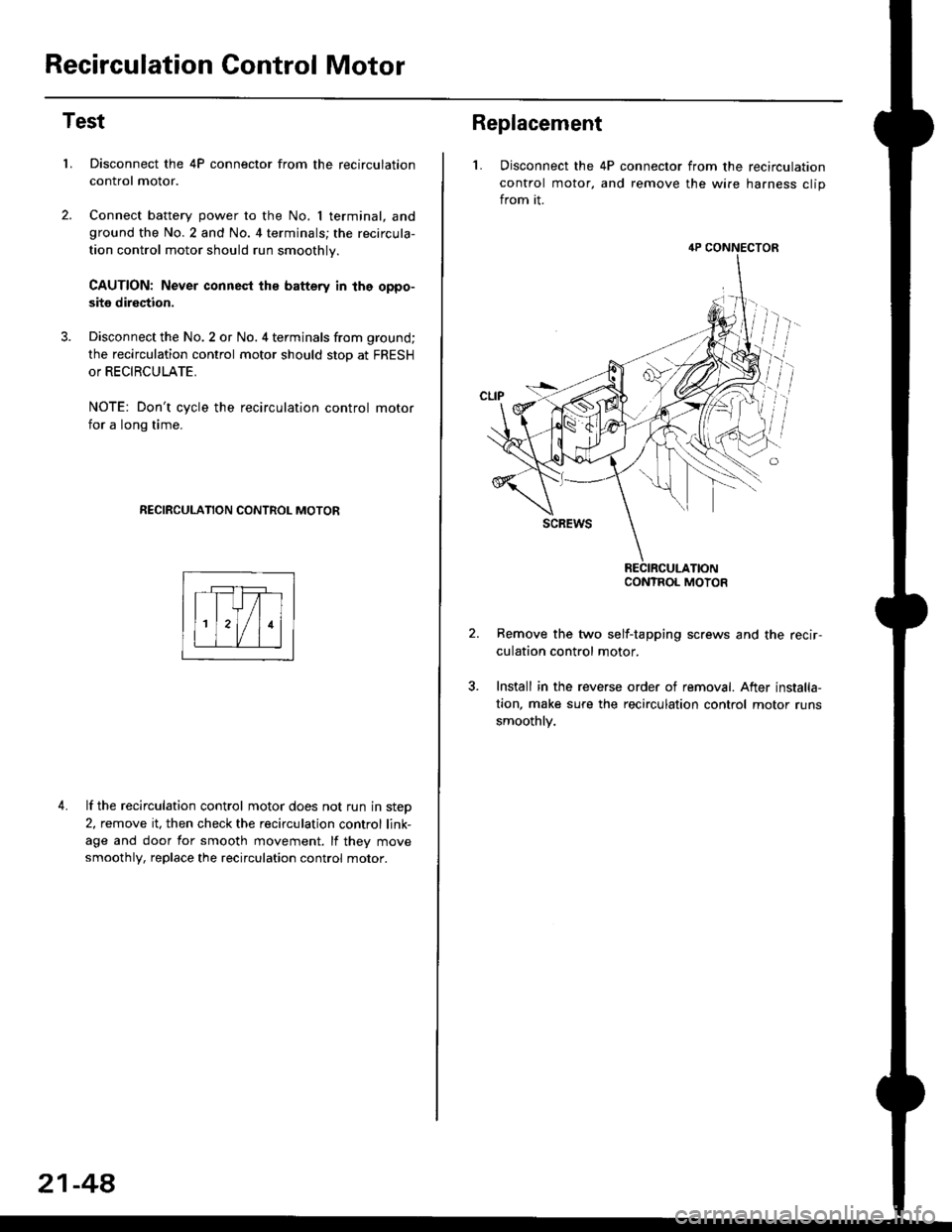
Recirculation Control Motor
Test
LDisconnect the 4P connector from the recirculation
control motor.
Connect battery power to the No. I terminal, andground the No.2 and No. 4 terminals; the recircula-
tion control motor should run smoothly.
CAUTION: Never connest ths battery in the oppo-
site direction.
Disconnect the No. 2 or No. 4 terminals from ground;
the recirculation control motor should stop at FRESH
or RECIRCULATE.
NOTE: Don't cycle the recirculation control motor
for a long time.
RECIRCULATION CONTROL MOTOR
4. lf the recirculation control motor does not run in step
2, remove it, then check the recirculation control link-
age and door for smooth movement. lf they move
smoothly, replace the recirculation control motor.
21-48
Replacement
L Disconnect the 4P connector from the recirculation
control motor, and remove the wire harness clip
from it.
Remove the two self-tapping screws and the recir-
culation control motor.
Install in the reverse order of removal. After installa,
tion, make sure the recirculation control motor runs
smoothly.
4P CONNECTOR
CONTROL MOTOR
Page 1433 of 2189
Condenser Fan
CONDENSER FAN RELAY 4P SOCKET
JUMPERwlRE
(cont'd)
22-9
Conden3er fan does not run at all.
Check the No. 56 (20 A) fuse in the
unde.hood frJse/relaY box, and the
No. 17 (7.5 A) fuse in the under-
dash fuse/relay box.
Reolace the fuse{s), and techeck
Remove the condenser lan rclaY'
and test it (see page 22 21i
Replace the condensei fan relav.
Check the under-hood tus6/relaY
Measure the vohage between the
No. 2 terminalofthe condenser fan
relav 4P socket and bodv ground.
ls there battery voltage?
Check the condenser lan Powersupply circuit:Connect the No. 1 and No. 2 teF
minals of the condenser fan relay
4P socket with a jumper wire
Does the condenser fan run?To page 22-10
Io page 22 11
Page 1435 of 2189
Check the diode:1. Disconnect the iumPer wire
2. Remove the A/C diode from
the under hood fuse/relaY box
3. Check for current flow in both
directions between the A and
B terminals.
ls there current flow in onlY
one direction?
Chock for an open in the wire:
1. Turn the ignition switch ON(ll).
2. Measure the voltage between
the No. 2 terminal of the AJC
diode 2P socket and body
ground.
Repair opon in the wire betwe€n
the No. 17 luse and the A/c
diode.ls there battery voltage?
B()-=iFA
A/C DIOOE 2P SOCKET
Page 1438 of 2189
![HONDA CIVIC 1996 6.G Workshop Manual Troubleshooting
Compressor lcontdl
COMPRESSOR CLUTCH RELAY4P SOCKET
l--;l
12 |---r--]l.l3 |L-J--J
] BLK/YEL
A(v)
!
ECM/PCM CONNECTOR A I32P}
Wire side of female terminats
*Howto use the backprobe set HONDA CIVIC 1996 6.G Workshop Manual Troubleshooting
Compressor lcontdl
COMPRESSOR CLUTCH RELAY4P SOCKET
l--;l
12 |---r--]l.l3 |L-J--J
] BLK/YEL
A(v)
!
ECM/PCM CONNECTOR A I32P}
Wire side of female terminats
*Howto use the backprobe set](/manual-img/13/6068/w960_6068-1437.png)
Troubleshooting
Compressor lcont'dl
COMPRESSOR CLUTCH RELAY4P SOCKET
l--;l
12 |---r--]l.l3 |L-J--J
] BLK/YEL
A(v)
!
ECM/PCM CONNECTOR A I32P}
Wire side of female terminats
*Howto use the backprobe setsConnect the backprobe adapters to the stackang patch cords, andconnect the cords to a multimeter. Using the wire insulation as aguide for the contoured tip of the backprobe adapter, gently slidethe tip into the connector from the wire side until it comes in con-tact with the terminalend ofthe wire (see section 11).
Frcm page 22-12
To page 22-15
Check Ior an open in the wire;1. Disconnecl the jumper wire.2. Turn the ignition swatch ON (ll).
3. l\4easure the voltage betweenthe No. 4 terminal of the com-pressor clutch relay 4P socketand body ground.
Repair open in the wire betw€enthe No. 17 fuso and the compres-sor clutch relav.
Check for an open in the wira:1. Turn the ignition switch OFF,then reinstall the compressorclutch relay.2. Make sure the A/C switch isOFF, then turn the ignitionswitch ON (ll).
3. Using a *Backprobe Set (T/N07SAZ 0010004), measurethe voltage between the No.17 terminal oI the ECM/PCMconnector A (32P) and bodyground with the ECM/PCMconnectors connected.
Repair open in the wirc betweonthe compressor clutch relay andthe ECM/PCtvt.
ls there battery voltage?
Page 1439 of 2189
Frcm page 22-14
Check lor an open in the wire:1. Turn the ignition switch OFF.
2. Disconnect the A/C pressure
switch 2P connector.3. Turn th ignition switch ON lll).4. Measure the voltage between
the No. 1 terminal of the AJCpressure switch 2P conneclorand body ground.
Check the A/C pressure switch:1. Turn the ignition switch OFF.
2. Check for continuity between
the No. 1 and No. 2 terminalsof the Ay'C pressure switch.
ls there continuity?
Check for A/C system ptessure.
ls the pressure within sPeci_f cations?Repair the A/C pressure Problem
A/C PRESSURE SWITCH 2P CONNECTOR
ls there battery voltage?
wire side of {emale terminals
A/C PRESSURE SWITCH
Repair open in the wire between
the condenser fan relay tnd the
A/C oressure switch.
1o page 22-16
(cont'd)
22-15
Page 1442 of 2189

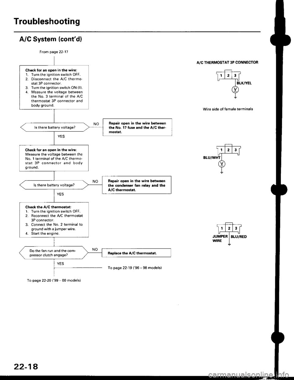
Troubleshooting
A/C System (cont'd)
From page 22-11
. _Ff,, __
I11213[
,r,il*"-T",-.r-'..owrRE I
To page 22-19 1'96 - 98 models)
A/C THERMOSTAT 3P CONNECTOR
Wire side oI female terminals
Check tor an open in the wire:1. Turn the ignition switch OFF.2. Disconnect the A/C thermostat 3P connector.3. Turn the ignition switch ON (ll).
4. Measure the voltage betweenthe No. 3 terminal of the Ay'Cthermostat 3P connector andbody ground.
Repai. open in the wire betweentho No. 17 tuso and the A/C the.-mostat.
Check loi an open in the wi.e:Measure the voltage between theNo. 1 terminal of the A,/C thermostat 3P connector and bodyground,
Ropair open in the wire betwoenthe condedlo. lan rolay and theA/C thormostat.
ls there battery voltage?
Check the A/C th6rmostat:1. Turn the ignition switch OFF.2. Reconnect the A,/C thermostat3P connector.3. Connect the No. 2 terminal toground with a iumperwire.4. Start the engine.
Do the fan run and the com-pressor clutch engage?
To page 22-20 ('99 - 00 models)
22-18
Page 1444 of 2189

Troubleshooting
('99 00 models)
From page 22 18
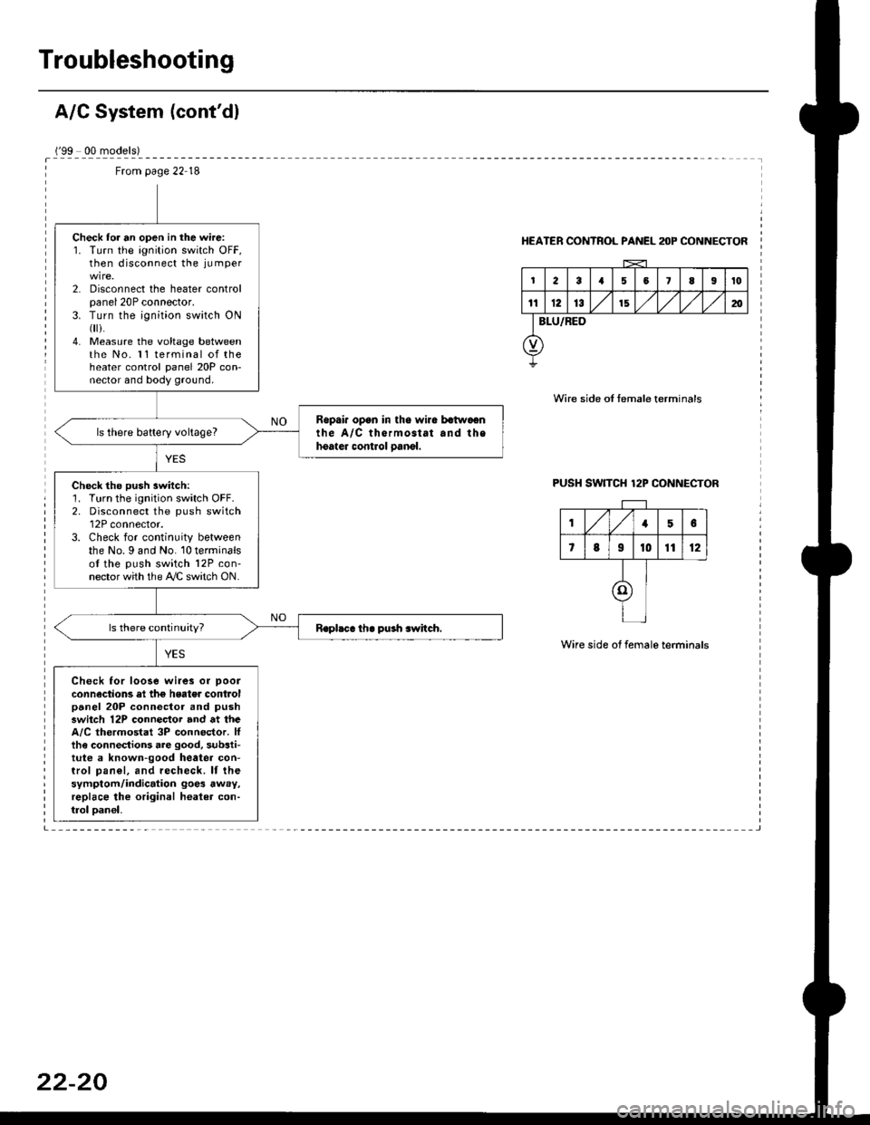
Check lor an open in the wire:1. Turn the ignition switch OFF,then disconnect the ju mper
2. Disconnect the heater controlpanel 20P connector.3. Turn the ;gnition switch ON{
i.4. Measure the voltage betweenthe No. 11 terminal of theheater control panel 20P con-nector and body ground.
Ropai. opan in tho wira batwaonthe A/C thermostat and thehoater control oanol.ls there battery voltage?
Check the push switch:1. Turn the ignition switch OFF.2. Disconnect the push switch12P connector.3. Check for continuity betweenthe No. I and No. 10 terminalsof the push switch 12P con-nector with the A/C switch ON.
Check for loose wi.es or poor
connections el the hgater controlpanel 20P connector and pushswitch 12P connector and at theA/C thermostat 3P connector. Ittha connections are good, substi-tute a known-good heatea con-trol pan€|, and recheck. lf thesymptom/indication goe3 away,replace lhe original healer con-trol oan€|,
HEATER CONTROL PANEL anP CONNECTOR
Wire side of temale terminals
PUSH SW]TCH 12P CONNECTOR
Wire side of female terminals
,/1,/156
7819t01112
I
I
I