Page 1216 of 2189
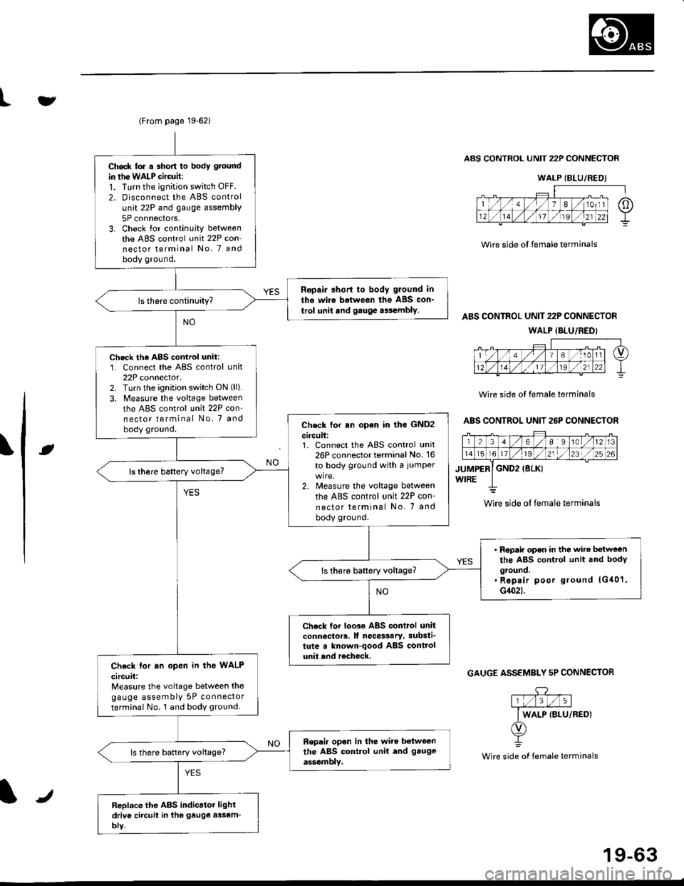
lFrom page 19-621
Ch6ck lor . short to body ground
in ihe WALP Gircuit:1. Turn the ignition switch OFF.
2. Disconnect the ABS control
unit 22P and gauge assembly
5P connectors.3. Check for continuity betweenthe ABS control unit 22P con-nector terminal No. 7 andbody ground.
Ropair short to body g.ound in
tho wire betweon the ABS con_
trol unit and gauge aasembly.
Check the AgS cortrol unit:1. Connect the ABS control unit22P connector.2. Turn lhe ignition switch ON (ll).
3. Measure the voltage between
the ABS control unit 22P con'nector terminal No, 7 and
body ground.Check tor rn open in lho GND2
circuit:1. Connect the ABS control unit26P connector terminal No. 16
to body ground with a iumper
2. Measure the voltage between
the ABS control unit 22P con-
nector terminal No. 7 and
body ground.
ls there baftery voltage?
' Repair op€n in the wit€ betweenthe ABS control unit and bodyground.. Rep.ir poor ground lG40'1,G1(}2t.
ls there battery voltage?
Check tor loo3€ ABS control unitconnector!. lf necesaary, substi_tute a known-qood ABS controlunit and r€check,Check lor an open in the WALP
circuit:Measure the voltage between thegauge assembly 5P connectorterminal No. 1 and body ground.
Ropai. opon in the wiro botweenthe ABS control unit end gauge
assemblv.ls there battery voltage?
Replace the ABS indicrtor lightdriv6 ci.cuit in the gtuge assem-bly.
tv
Wire side ol female terminals
ABS CONTROL UNIT 22P CONNECTOR
ABS CONTROL UNIT 22P CONNECTOR
WALP {BLU/REDI
Wire side ol female terminals
ABS CONTROL UNIT 26P CONNECTOR
rt
GAUGE ASSEMBLY 5P CONNECTOR
.DY
Wire side of female terminals
WALP {BLU/REDI
wire side ol female terminals
J
19-63
Page 1219 of 2189
Troubleshooting
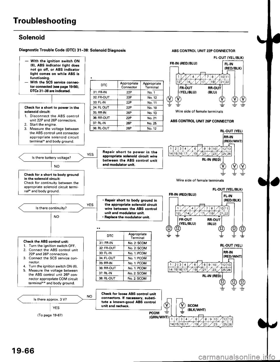
Solenoid
Diagnostic Trouble Code {DTC} 31-38: Solenoid Diagnosis
YES
ABS CONTROL UNIT 22P CONNECTOR
Wire side of female terminals
ABS CONTROL UNIT 26P CONNECTOR
FL.OUT (YEL/ALK)- With the ignition switch ON(lll, ABS indicator light doesnol go oft. or ABS indic.to.light comes on while ABS i3functioning.- With the SCS servico connec-tor connected ls€. pag€ 19-561,DTCa 31-38 are indicstod.
Check for a short lo powor in thosol6noid circuitl1. Disconnect the ABS controlunit 22P and 26P connectors.2. Sta rt the engine.3. Measure the voltage betweenthe ABS control unit connectorappropriate solenoid circuitterminal* and body ground.
Ropri. short to powor in thcappropriate solanoid ci.cuit wirobotw6.n ths ABS cont.ol unitand modulrtor unit.
ls there battery voltage?
Check for a short to body groundin the 3olenoid circuit:Check tor continuity between theappropriate solenoid circuit termi-nal* and body ground.
. Repair short to body ground inlhe .ppropriato solonoid circuitwire betwoan th6 ABS controlunit and modllato. unit.. Replaco the modul.tor unit.
Check th€ ABS control unit:'1. Turn the ignition switch OFF.2. Connect the ABS control unit22P and 26P connectors.3. Connect the SCS service con-
4. Turn the ignition switch ON {ll}.5. Measure the voltage betweenthe ABS control unit 26P con-nector appropriate CONI circuitterminal++ and body ground.
Check for loos€ ABS control unhconnectora. It naceslrry, aub3ti-tutc . known-good ABS controlunit tnd recheck.
ls there approx. 3 V?
DTCAppropriateConnectorAppropriateTerminal
31: FRJN22PNo. 1
32: FR-OUT22PNo.12
33i FL'IN22PNo. 11
34: FL OUT22PNo.10
3s: RRIN26PNo.13
36: RR-OUT22PNo. 21
37: RLIN26PNo.25
38: RL-OUT26PNo.12RL.OUT IYEL}
Wire side of female terminals
DTCAppropriateTerminal
31: FR-lNNo. 2: SCOM
32: FR-OUTNo. 2: SCOM
33i FLINNo. 1: rcOM
34: FL-OUTNo. l: PCOM
35: RR{NNo.1:PCOM
36: RR-OUTNo. 1: rcOM
37rRL'lNNo. 2: SCOM
38: RL-OUTNo. 2: SCOM
RL.OUT (YEL}
19-66
(To page 19-671
Page 1222 of 2189
tt
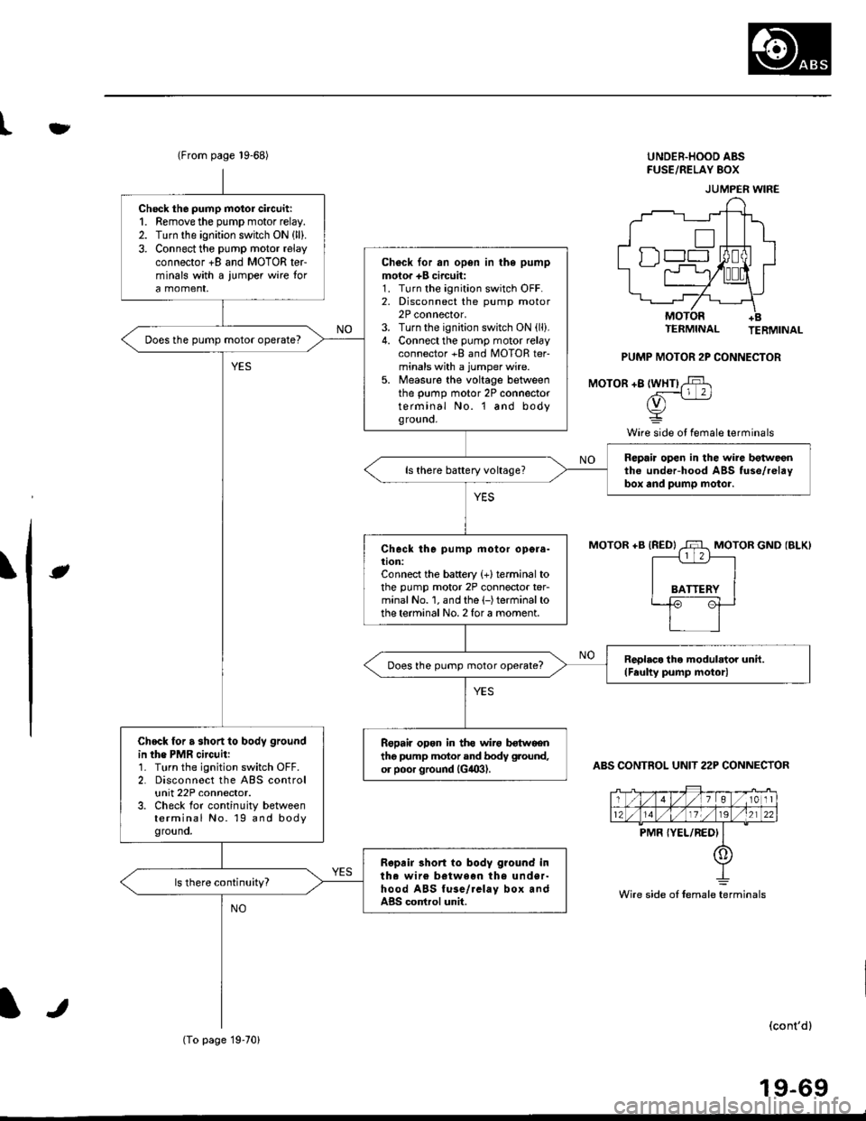
(From page 19-68)UNDER.HOOD ABSFUSE/RELAY 8()X
TERMINAL TERMINAL
PUMP MOTOR 2P CONNECTOR
MOTOR +8 lWHTl,$
rv) -
Y
Wire side ot female terminals
\lt
MOTOR +B {RED}MOTOR GND (BLK)
ABS CONTROL UNIT 22P CONNECTOR
(cont'dl
19-69
JUMPER WIRE
Wire side oI female terminals
Check the pump motor circuit:1. Remove the pump motor relay.2. Turn the ignition switch ON (ll).
3. Connect the pump motor relayconnector +8 and MOTOR terminals with a iumper wire tora momenr,
Ch€ck for an open in the pump
moior +B circuit:1. Turn the ignition switch OFF.2. Disconnect the pump motor2P connector,3. Turn the ignition switch ON (ll).
4. Connect the pump motor relayconnector +B and MOTOR ter-minals with a jumper wire.5. Measure the voltage betweenthe pump motor 2P connectorterminal No. l and bodyground.
Does the pump motor operate?
Repaia open in the wire botweentho under-hood ABS fuse/relaybox and pump motor.ls there battery voltage?
Check the pump motor opgra-tion:Connect the battery {+}terminal tothe pump motor 2P connector ter-minal No. 1. and the (-)terminalto
the terminal No. 2 for a moment.
ReDlaco lho modulator unit.(Feulty pump motor)Does the pump motor operate?
Chock for a short to body ground
in the PMR circuit:1. Turn the ignition switch OFF.2. Disconnect the ABS controlunit 22P connector.3. Check for continuity betweenterminal No. 19 and bodygrouno,
Repail opon in ths wirg botwgentho pump motor and bodv ground,
or poor ground (G,!09).
Ropair 3hort to body g?ound intha wire between the under-hood ABS fuse/rclay box andABS cortrol unit.
(To page 19-70)
Page 1281 of 2189
Troubleshooting
SymptomProbable Cause
Water leaks1. Clogged drain tube.
2. Gap between glass weatherstrjp and roof panel.
3. Defective or improperly installed glass weatherstrip.
4. Gap between drain seal and roof panel.
Wind noise'1. Excessive clearance between glass weatherstrip and roof panel.
Motor noise1. Loose motor.
2. Worn gear or bearing.
3. Cable assembly deformed.
Glass does not move, but motor turns'1. Clutch out of adjustment.
2. Foreign matter stuck between guide rail and slider.
3. lnner cable loose.
4. Cable assembly not attached properly.
Glass does not move and motor does not turn
{glass can be moved with moonroof wrench)
1. Blown fuse,
2. Faulty switch.
3. Battery run down.
4. Defective motor.
5. Faulty relay.
D
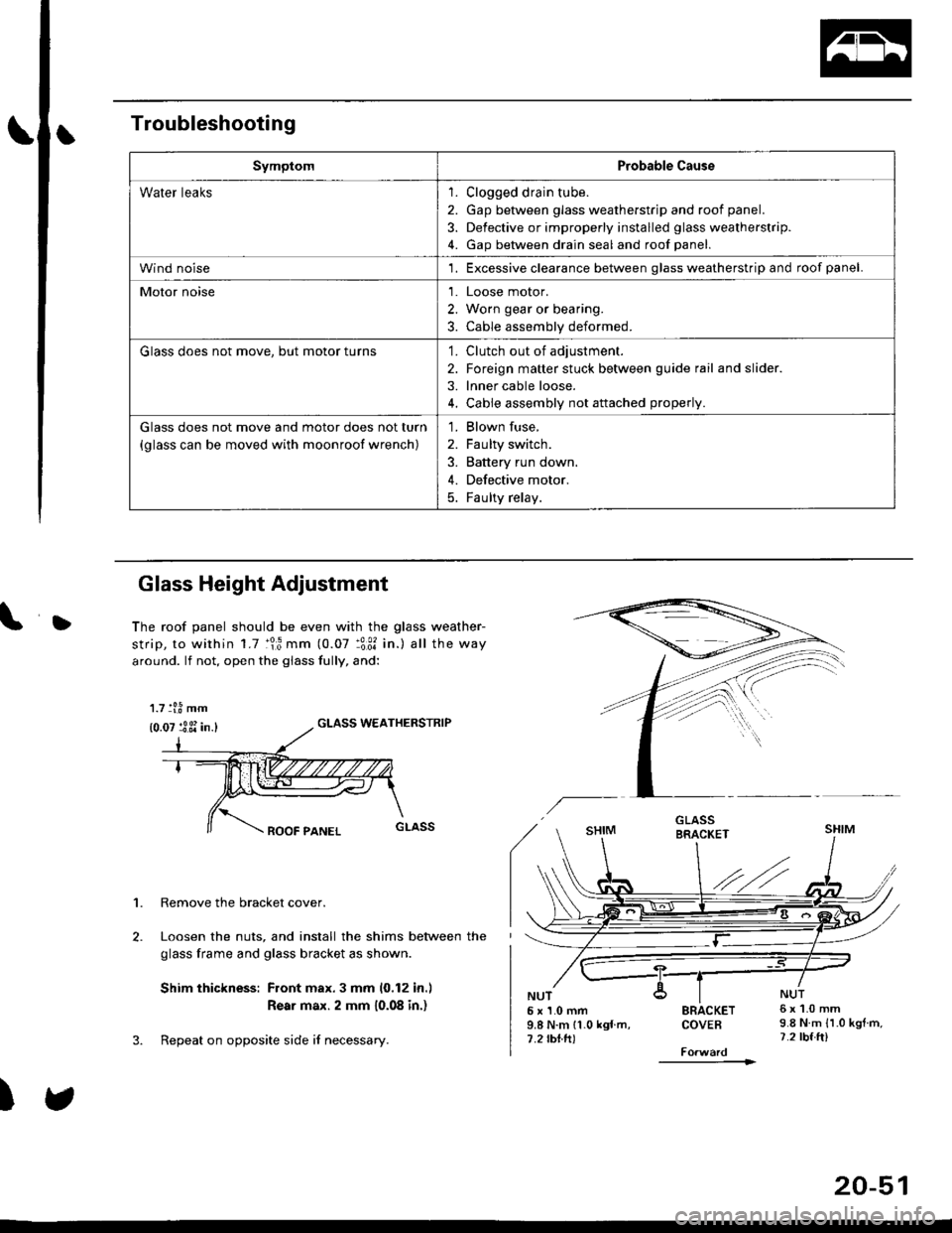
Glass Height Adjustment
The roof panel should be even with the glass weather-
strip, to within 1.7 :lr3 mm (0.07 :3:31 in.) all the way
around. lf not, open the giass fully, and:
GLASS WEATHERSTRIP
1. Remove the bracket cover.
Loosen the nuts, and install the shims between the
glass frame and glass bracket as shown.
Shim thickness: Front max.3 mm 10,12 in.l
Rear max. 2 mm 10.08 in.)
Repeat on opposite side i{ necessary.
)
5x1.0mm9.8 N.m 11.0 kgf m,7.2 rbtft)
SRACKETCOVEB
----------1>
6x1.0mm9.8 N.m {1.0 kgtm,7.2 tbf.ft)
1.7 tl.8 mm
{0.07 :3 3i in.}
20-51
Page 1384 of 2189
Troubleshooting -'96 - 98 Models
Blower Motor
BLOWER MOTOR 2P CONNECTOR
Wi.e side of fernale terminals
f=
l1l
r,l
ruumifalulau**'
I
Fl gr-urwnr
l1|_-_-l
t4 ,t
I
glower motor does not run at all.
Check the No.55 (40A)luse in theunder hood fuse/relay box, andthe No. 17 (7.5 A) luse in theundeFdash luse/relay box.
Repl.ce th. fuse{rl, .nd rochack.
Check the blower motor:1. Connect the No. 2 terminal ofthe blower motor 2P connoctor to body ground with a
lumper wrre.2. Turn the ignition switch ON (ll).
Does the blower motor run?
Chock for an opsn in the wire:1. Disconnect the ,umper wireand the blower motor 2P con-nector,2. Measure the voltage betweenthe No. 1 terminal and bodyground.
ls there battery voltage?
Ch6ck tha blower motor relay:1. Turn the ignition switch OFF.2. Remove the blower motorrelay from the under-hoodfuse/relay box, and test it (see
page 21-49).
Replace tha blower moior reley.
To page 21-11
fo page21'12
21-10
Page 1387 of 2189
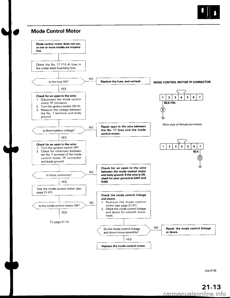
Mode Control Motor
To page 21-14
MODE CONTROL MOTOR 7P CONNECTOR
'1
I2I57
BLK/YEL
Wire side of female terminals
Mode control motor does not run,
or one of more modes are inoPela-
Check the No. '17 (7.5 A) fuse in
the under-dash fuse/relaY box.
Reolace the fuse, and recheck.
Check lor an open in the wire:
1. Disconnect the mode controlmotor 7P connector.2. Turn the ignition switch ON (ll).
3. Measure the voltage betweenthe No. l terminal and bodyg rou nd.
Repair open in the wire between
the No. 17 tuse and the mode
control motor.ls there batterY voltage?
Check {or an open in the wire:1. Turn the ignition switch OFF.
2. Check for continuity between
the No. 7 terminal of the mode
co nlrol motor 7P connector
and body ground.
Check for an open in the wire
batwe€n the mode contrcl motol
and body ground. lf the wir€ is OK,check for poor gtound at G/U)l and
G402.
ls there continuity?
Test the mode control motor (see
page21-471.Check the mod€ control linkage
and doors:1. Bemove the mode controlmotor (see page 21-47).2. Check the mode control linkageand doors for smooth move
ls the mode control motor OK?
Do the mode control linkageand doors move smoothlY?
Reolace the mode control motor,
I34561
BLK
[]
(cont'd)
Page 1390 of 2189
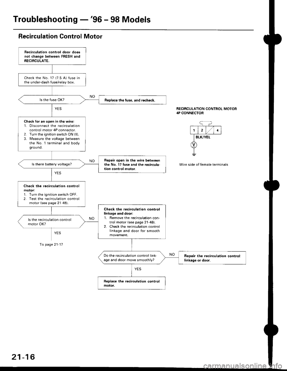
Troubleshooting -'96 - 98 Models
Recirculation Control Motor
Becirculation control door doesnot change between FRESH andRECIBCULATE.
check the No- 17 (7.5 A) fuse inthe under-dash fuse/relay box.
Reolace the tuse. and recheck.
Check for an open in the wire:1. 0isconnect the recirculationcontrol motor 4P connector.2. Tu.n the ignition switch ON (ll).
3. Measure the voltage betweenthe No. l terminal and bodyground.
Repair open in the wir6 betweenthe No. 17Iuse and the recircula-lion conlrol motor.ls there battery voltage?
Check lhe recirculation control
1. Turn the ignition switch OFF.2. Test the recirculation controlmotor {see page 21 48).
Check the recirculation controllinkage and door:1. Remove the recirculation con'trol motor {see page 21 48}.2. Check the recirculation controllinkage and door for smooth
Do the recirculation control linkage and door move smoothly?Reoair the r€circulation controllinkage or door.
RECIRCULATION CONTROL MOTOR4P CONNECTOR
BLK/YEI-
Wire side of temale terminals
Io page 21 17
21-16
Page 1392 of 2189
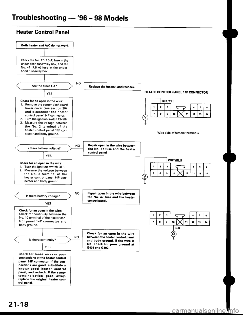
Troubleshooting -'96 - 98 Models
Both heater and A/C do not work.
Check the No. 17 {7.5 A) fuse in theunderdash fuse/relay box, and theNo. 47 (7.5 A) fuse in the underhood fuse/relay box.
R.phce the fuso{s), .nd rccheck.
Chack tor an open in the wi.e:1. Remove the center dashboardlower cover (see section 20),and disconnect the heatercontrol panel 14P connector.2. Torn the ignition switch ON {ll).3. Measure the voltage betweenthe No. 2 terminal of theheater control panel 14P con-nector and body ground.
Rcpair opGn in th€ wiro betwoonthe No. 17 tuse and the hoatclcontrol panel.
ls there baftery voltage?
Check for an opon in the wiro:1. Turn the ignition switch OFF.2. Measure the voitage betweenthe No. 3 terminal of theheater control panel 14P con-nector and body ground.
Rgprii open in th6 wira b€twacnthe No. il7 tui. and the heat.tcont.ol p.nal.
ls there battery voltage?
Check foi an open in the wi.e:Check for continuity between theNo. 10 terminal ot the heater con-trol panel 14P connector andbody ground.
Check lor an opon in tho wireb€{w6on the hoator control oaneland body ground. lI the wirc isOK, check tor poor ground atG401 .nd G4O2.
Check for looae wiaos or ooolconnections at the hoater controlpanol 14P connector. lf the con-nactions dre good. 3ubstitute tknown-9ood heater controlpanel, and rech6ck. It tho symp-tom/indication 9oe3 .wry,replace the original heatel con-trol oanol.
Heater Control Panel
HEATER CONTROL PANEL 1,lP CONNECTOR
Wire side of female terminals
21-18