Page 129 of 2189

Timing Belt
Inspection
1.
2.
3.
Remove the cylinder head cover.
. Refer to page 6 46 when installing.
Remove the upper cover (see page 6 19).
Inspect the timing belt for cracks and oil or coolantsoakrng.
NOTE:
. Replace the belt if oil or coolant soaKeo.. Remove any oil or solvent that gets on the belt.
Rotate pulleyand inspect belt.
After inspecting, retorque the crankshaft pullev bolt{see page 6- 16).
o- I6
Tension Adjustment
CAUTION: lt*ays aa;j"t the timing bett rension withthe engine cold.
NOTE:
. The tensioner is spring loaded to apply tension to thebelt automatically after making the following adjustment.
. Always rotate the crankshaft counterclockwise whenviewed from the pulley side. Rotating it clockwisemay result in improper adjustment of the belt ten-sion.
. lnspect the timing belt before adjusting the belt ten-ston.
1.Remove the cylinder head cover.
. Refer to page 6,46 when installing.
Remove the upper cover (see page 6,'19).
Rotate the crankshaft five or six revolutions to setthe belt.
Set the No. 'l piston at TDC (see page 6-21).
Loosen the adjusting bolt 180'.
2.
3.
4.
5.
\I
ADJUSTING BOLT44 N.m {4.5 kgt m,33 rbf.ft)
7.
8.
Rotate the crankshaft counterclockwise three teethon the camshaft pulley.
Tighten the adjusting bolt.
After inspecting, retorque the crankshaft pulley bolt(see page 6-16).
Page 134 of 2189

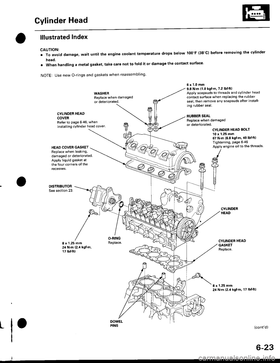
Gylinder Head
lllustrated Index
CAUTION:
. To avoid damage, wait until the engine coolant temperatule drops below 100"F (38'C) before removing the cylinder
head.
. When handling a metal gasket, take care not to fold it or damage the contact surface'
NOTEr Use new O-rings and gaskets when reassembling'
CYLINDER HEAD
COVERRefer to page 6 46, when
installing cylinder head cover.
WASHERReplace when damaged
or deteriorated.
O.RINGReplace.
6x1.0mm9.8 N.m 11.0 kgf.m, 7.2 lbfft)Apply soapsuds to threads and cylinder head
contact surface when replacing the rubber
seal, then temove any soapsuds after install
ing rubber seal.
RUBBER SEALReplace when damagedor deteriorated.
CYLINDER HEAD BOI-T
10 x 1.25 mm67 N.m 16.8 kgf m, a9 lbt'ft)
Tightening, Page 6-46
Apply engine oilto the threads.HEAD COVEB GASKETReplace when leaking,
damaged or deteriorated.Apply liquid gasket at
the four corners ol therecesses,
DISTRIBUTORSee section 23.
8 x 1 .25 mm24 N.m (2.4 kgf.m,17 tbt.ft)
CYLINDER HEADGASKETReplace.
8 x 1.25 mm24 N.m {2.4 kgf m, 17 lbf ftl
t(cont'd)
6-23
PINS
Page 138 of 2189

Removal
Engine removal is not required for this procedure
!!!s@ Make sure iacks and salety stands are
f ta"eata"ea propetty and hoist brackets are attached to the
correct positions on the engine.
CAUTION:
. Use tender covels to avoid damaging painted sul-
faces.
o To avoid damage, unplug the wiling connectors
carefully while holding the connector portion to
avoid damage.
. To avoid damaging the cylinder head, wait until the
engine coolant temperature drops below 100"F
{38"C} before loossning the tetaining bolts.
NOTE:
o Mark all wiring and hoses to avoid misconnectlon
Also, be sure that they do not contact other wiring or
hoses, or interfere with other parts.
. Inspect the timing belt before removing the cylinder
h ead.
. Turnthe crankshaft pu lley so that the No. lpistonisat
top dead center (see Page 6-21)
'1. Disconnect the negative terminal from the battery'
Drain the engine coolant (see page'10-7).
a Remove the radiator cap to speed draining.
Remove the intake air duct and air cleaner housing
(see page 5 3).
Remove the mounting bolt and lock bolt. then
remove the power steering (P/S) pump belt and
pump (see page 5'5).
Loosen the idler pulley center nut and adjusting
bolt' then remove the air conditioning (A'lc) com-
pressor belt (see Page 5-6).
Loosen the mounting nut and lock bolt. then
remove the alternator belt (see page 6-19).
Remove the P/S pump bracket (see page 5-12).
3.
4.
2.
6.
1.
8. Remove the throttle cable by loosening the locknut,
then slip the cable end out of the throttle linkage
NOTE:
. Take care not to bend the cable when removing it
Always replace any kinked cable with a new one
. Adjust the throttle cable when installing (see sec-
tion 1 1).
D16Y7 engine:
Dl6Y5, Dl6Y8 engines:
THFOTTLECABLE
(cont'd)
6-27
LOCKNUT
CABLE
Page 171 of 2189

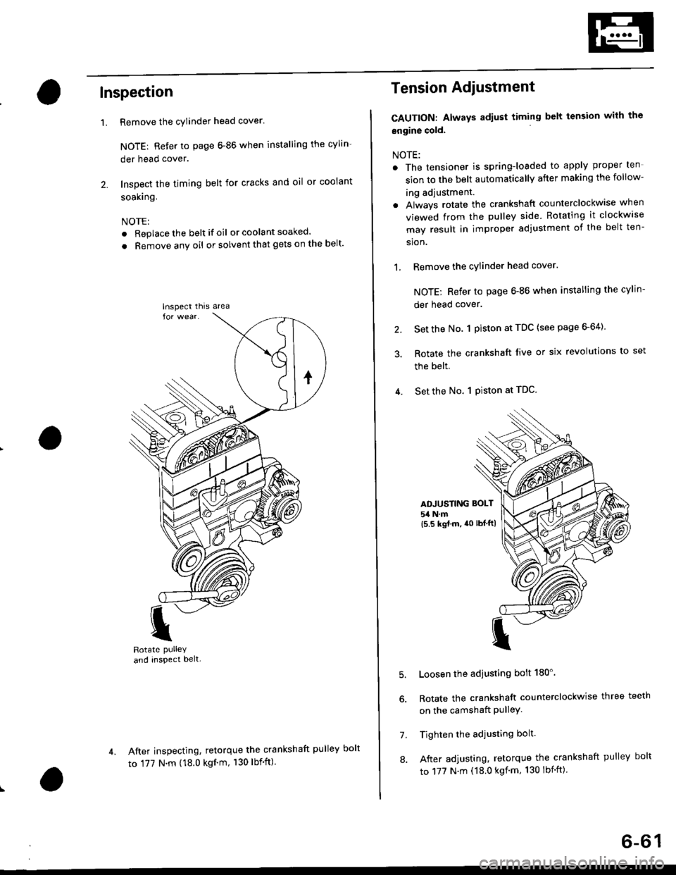
Inspection
Remove the cylinder head cover.
NOTE: Refer to page 6-86 when installing the cylin-
der head cover.
Inspect the timing belt for cracks and oil or coolant
soakrng.
NOTE:
. Replace the belt if oil or coola nt soaked.
. Remove any oil or solvent that gets on the belt'
I
Rotate PUlleYand inspect belt-
After inspecting, retorque the crankshaft pul
to 177 N.m (18.0 kgf'm, 130 lbf'ft)
'L
lnspect thrs area
Tension Adiustment
CAUTION: Always adiust timing belt tension with the
engine cold.
NOTE:
. The tensioner is spring-loaded to apply proper ten
sion to the belt automatically after making the follow-
ing adjustment.
. Always rotate the crankshaft counterclockwise when
viewed from the pulley side. Rotating it clockw'se
may result in improper adjustment of the belt ten-
sion.
1, Remove the cylinder head cover.
NOTE; Refer to page 6-86 when installing the cylin-
der head cover.
2. Set the No. 1 piston at TDC (see page 6-64)
3. Rotate the crankshaft live or six revolutions to set
the belt.
4. Set the No. 1 Piston at TDC
ADJUSTING BOLT
54 N.m(5.5 kgt.m, a0 lbtftl
5.
7.
8.
Loosen the adjusting bolt 180'.
Rotate the crankshaft counterclockwise three teeth
on the camshaft PulleY.
Tighten the adjusting bolt.
After adjusting, retorque the crankshaft pulley bolt
to 177 N.m (18.0 kgf'm, 130 lbnft)
ley bolt
6-61
Page 175 of 2189
Cylinder Head
lllustrated Index
CAUTION:
. To avoid damaging the cylinder head, wait until the engine coolant tempsraturo drops below 100"F (38"C1 bofote
removing it,
. when handling a metal gasket, take caro not to fold the gaskot or damage the contact surface of the gasket.
NOTE: Use new O-rings and gaskets when reassembling.
CYLINDER HEAO
PLUGReplace.
)@
DISTRIBUTOR
8 x 1 ,25 mm
27 N.m P.E kgl m.
20 tbf.foApply engine oil to
the threads.
cr.rMp.S
CAMSHAFT A"o''*t*'; wes@
OIL SEALReplace.
6 x l,omm9.8 N'm tl.0 kgt'm,7.2lbf ft)
RUBBER SEALReplace when damaged
or detedorated.
6x1.0mm9.8 N.m (1.0 kgf'm,
7.2 rbnftl
fi%
IGNMONWIRE COVER
CYLINOER HEAD
COVERRefer to page 6-86
when installing
HEAD COVER GASKETReplace when leaking, damaged
or deteriorated.Apply liquid gasket at thecorners of the recesses, Page 6-86
8 x 1,25 mm24 N.m {2.4 kgf'm,
1? tbf.ftl
EXHAUST
10 x 1.25 mm56 N.m (5.7 kgf m,,r1 lbl.ft)
(cont'd)
6-65
Page 256 of 2189
Cooling
fllustrated Index ."..."... ""' 10-2
Radiator
Replacement .'....'...."..."
Engine Coolant Refilling and
Bleeding
Cap Testing
Testing
Thermostat
Replacement .............'....
Testing
10-6
10-7
10-9
10-9
10-10
10-10
Engine Goolant TemPerature
(ECT) Switch
Testing """ 10-11
Water PumP
fffustrated Index ......'... " 10-12
Inspection ' 10'14
Replacement ..'..'...."...'.'....'..'.....'.""" 10-14
!
Page 257 of 2189

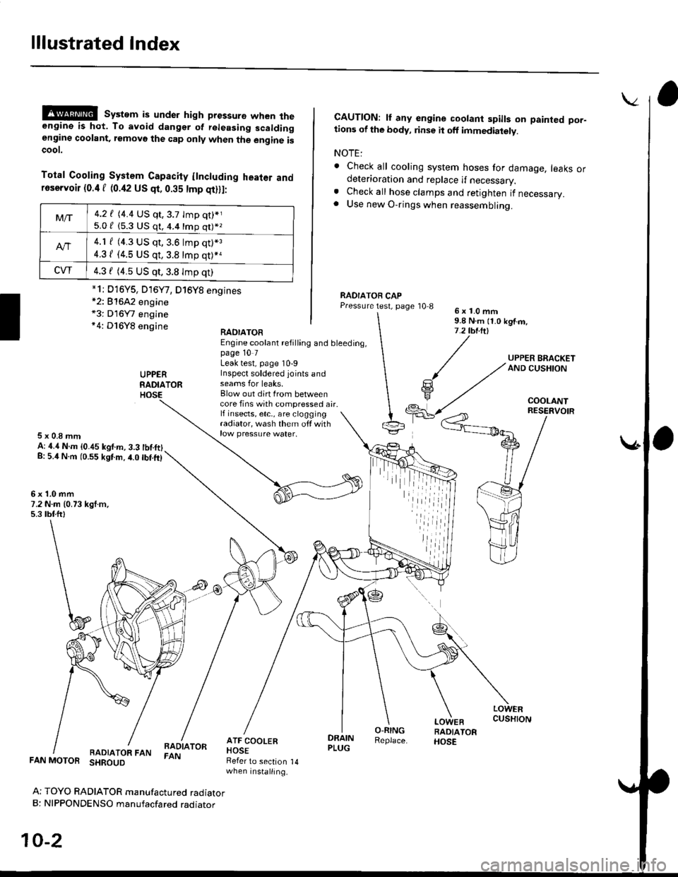
lllustrated Index
@@ system is under high pressure when theengine is hot. To avoid dangsr of rsleasing scaldingengine coolant, removo the cap only when the engine iscoot.
Total Cooling System Capacity flncluding heater andfoservoir (0.4 f (0.42 US qt, 0.35 tmp qt)ll:
*2: 81642 engine*3: D16Y7 engine*4: D16Y8 engine
CAUTION: lf any engine coolant spills on painted por-tions of the body, rinse it off immediately.
NOTE:
. Check all cooling system hoses for damage, leaks ordeterioration and replace if necessary.. Check all hose clamps and retighten if necessary.. Use new O-rings when reassembling.
RADIATOR CAPPressure test, page '10 86x1.0mm9.8 N.m {1.0 kgtm,7.2 tbt.ltl
UPPERRADIATORHOSE
UPPER BRACKETAND CUSHION
COOLANT
RAOIATOREngine coolant refilling and bleeding,page 10 7Leak test, page 10-9Inspect soldered joints andseams for leaks,Blow out dirt Irom betweencore fins with compressed air.lf insects, etc,, are cloggingradiator, wash them off withrow pressure water.
RESERVOIR
5x0.8mmA: ,1.4 N.m {0.45 kgf.m, 3.3 tbtftlg: 5.4 N.m (0.55 kgtm.4.0 tbf.ft)
6x1.0mm7.2 N.m (0.73 kgt.m,5.3 tbtftl
LOWERCUSHION
RADIATOR FANBADIATORFAN
DRAINPLUG
O-RINGReplace.
LOWEBRADIATORHOSE
FAN MOTOR SHROUD
Ar TOYO RADIATOR manufactured radiatorB: NIPPONDENSO manufacfared raoraror
10-2
Refer to section 14when installing.
Mt-|-4.2 f (4.4 US qt,3.7 tmp qt)*j
5.0 / (5.3 U$ q1, 4.4 16p q11*z
4.1 f (4.3 US qt, 3.6 lmp q0*3
4.31 (4.5 US qt, 3.8 tmp qt)*a
CVT4.3 f (4.5 US qt,3.8 Imp qt)
*1i D16Y5, D16Y7, D16Y8 engines
iil
Page 261 of 2189
Radiator
Replacement
Drain the engine coolant.
Remove the upper and lower radiator hoses, andATF cooler hoses.
Disconnect the fan motor connector.
Remove the radiator upper bracket, then pull up theraotator,
RADIA
ATF COOLERHOSES (A/T)Refer to sectionwhen installing.
UPPER RAOIATOR HOSE
6x1.0mm7.2 N.m (0.73 kgf.m.5.3 tbf.ft)
1.
2.
3.
5. Remove the fan shroud assemblies and other partsfrom the radiator.
Install the radiator in the reverse order of removal:
NOTE:
. Set the upper and lower cushions securely.. Fill the radiator with engine coolant and bleedthe air.
6x1.0mmCAPY|lT,PS:|" i.i ru- ii b rgr.-,AND CUSHION7.2 tbr.ftl
14
(
I
RESEBVOIR TANK
RADIATOR
LOWER CUSHION
RAOIATOR FAN/SHROUDASSEMBLY
DRAIN PLUGO-RINGReplace.
LOWER RAOIATOR HOSE
ATF COOLERPIPES {A/T)
,iiiiii
10-6