Page 1635 of 2189

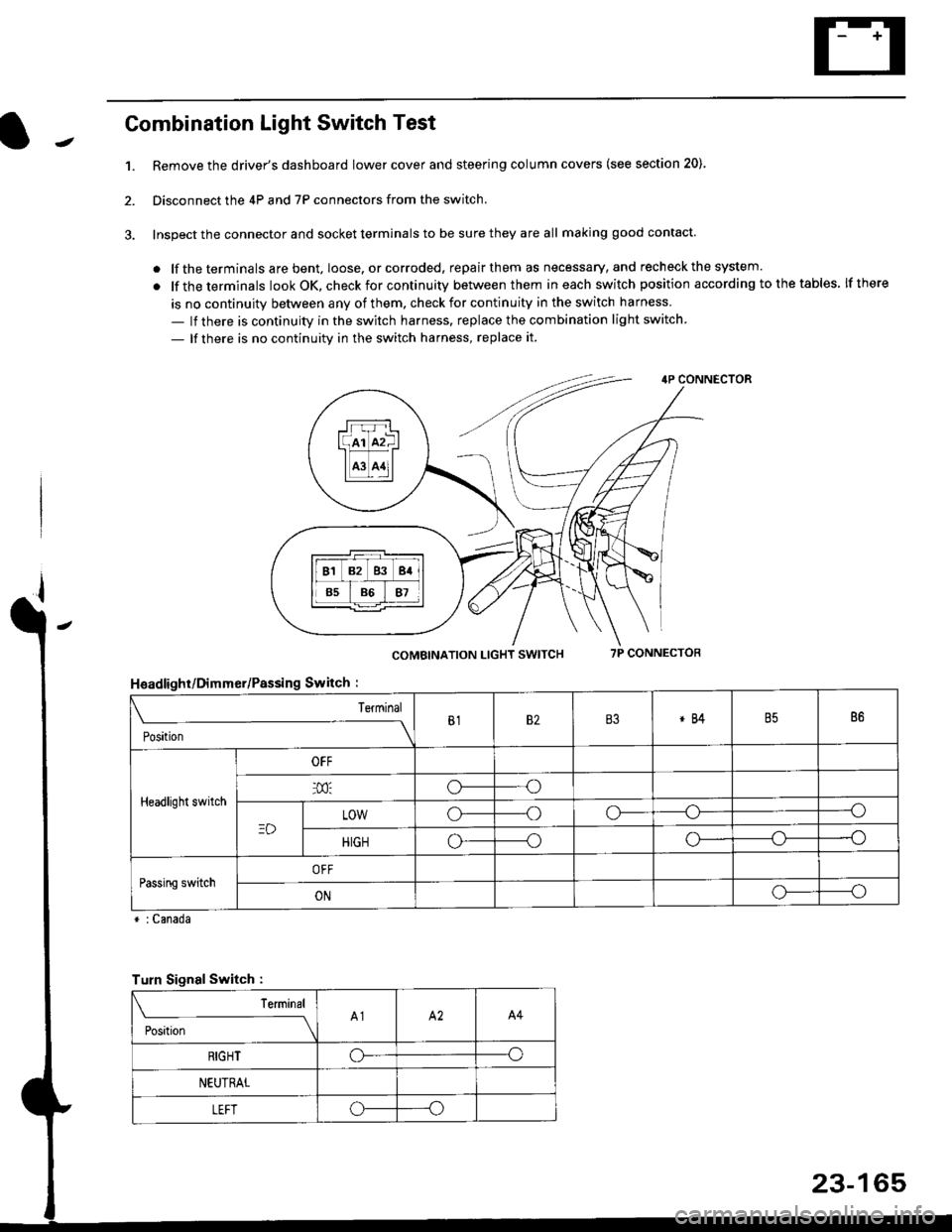
Combination Light Switch Test
1.Remove the driver's dashboard lower cover and steering column covers (see section 20)
Disconnect the 4P and 7P connectors from the switch.
Inspect the connector and socket terminals to be sure they are all making good contact
. lf the terminals are bent, loose. or corroded, repair them as necessary, and recheck the system.
. lf theterminals look OK, check for continuity between them ineach switch position according tothetables lfthere
is no continuity between any of them. check for continuity in the switch harness
- lf there is continuity in the switch harness. replace the combination light switch
- lf there is no continuity in the switch harness, replace it.
2.
4P CONNECTOR
COMBINATION LIGHT SWITCH7P CONNECTOR
HsadlighUDimmer/Passing Switch :
* : Canada
rrr r-l
l(rr mf ItffiTI A3 A11l
Terminal
Position
B182B3*84B586
Headlight switch
OFF
o---o
LOWo---oo-----o
HIGHo-----oo---o
Passing switchOFF
ONo-----o
Turn Signal Switch :
Teminal
;',*;----__\A1A2A4
RIGHToo
NEUTRAL
LEFToo
23-165
Page 1983 of 2189

A/T Gear Position Indicator (conrd)
- How the Circuit Works
With the ignition switch in ON (ll) or START (lll),
voltage is applied to the A,/T gear position indicator.
The A,/T gear position switch provides a ground for
each position. As an input is grounded, its indicator
light comes on. lf you select R, for example, ground
will be provided to the input of the A,/T gear position
indicato( and the R indicator will come on.
With the headlight switch in PARK or HEAD, voltage
is applied to the RED/BLK wire terminal. This
changes the indicator panel illumination from fixed
to controlled by the dash lights dimmer input
through the RED wire.
When the powertrain (all except '96-'98 CVT) or
transmission ('96198 CVT) control module (PCM or
TCM) detects an abnormality in the automatic
transmission control system, or when you request
diagnostic trouble codes through the service check
connector, the PCM or TCM will make the D4 (D for
CVT) indicator light blink.
Refer to the Service Manual (Section 14,
Automatic Transmission) for specific tests or
troubleshooting procedures.
\ia
89-2
Page 2006 of 2189

Headlights (cont'd)
- How the Circuit Works
Low Beams
With the headlight switch in HEAD and the dimmer
switch in LO, current tlows through the headlight
switch. fuse 21 . fuse 22. and the low beam
tilaments to ground, and the low beams come on.
High Beams
With the headlight switch in HEAD and the dimmer
switch in Hl, current flows through the headlight
switch, dimmer switch, fuses 4, 5, and the high
beam filaments to ground, and the high beams
come on.
Current also llows through the high beam indicator
light to ground. The high beam indicator comes on
to remind the driver that the high beams are on.
Flash-to-Pass
The flash feature works with the headlight switch in
OFF, PARK, or HEAD (low beams). When you move
the flash-to-pass switch to ON, current flows
through the switch, fuses 4 and 5, and the high
beam filaments to ground, and the high beams
flash. The high beam indicator also flashes during
the flash operation. The flash function has no effect
if the high beams are already on
Daytime Running Lights (Canada)
When you turn the ignition to ON (ll) with the
parking brake released, the daytime running lights
control unit supplies battery voltage at the
WHT/RED wire. This voltage is applied to the high
beam headlights through the daytime running lights
resistor. Each high beam headlight receives less
than battery voltage causing them to come on at
reduced brightness.
lf the parking brake is set, a ground signal is applied
to the daytime running lights control unit at the
RED/GRN wire. lf the parking brake is set when you
first turn the ignition switch to ON (ll), the high beam
headlights will remain off until you release the
parking brake. Once the high beam headlights are
on, setting the parking brake will not turn them ofi.
When low or high beam operation is requested,
battery voltage from the headlight switch is applied
to the daytime running light control unit via the RED
wire. The daytime running lights control unit then
turns off the headlights.
Refer to the Service Manual (Section 23, Electrical)
for specific tests or lroubleshootrng procedures.
110-14
Page 2129 of 2189

Connector Views (cont'd)
63. ABS ControlUnit
- Above right kick Panel
Connector A
- Orange- On main wire harness
1 RED/BLU (FR-|N)
3-
4 BRN (SCS)
7 BLU/BED (WALP)
8 '96197 models:
BLU|YEL (Not used)
9_
10 YEUBLK (FL-OUT)
11 RED/BLK (FL-|N)
Connector B
- Orange- On main wire harness
1 GRN^VHT (PCOM)
2 BLr(wHT {SCOM)
3 BLIVBLU (lG2)
4 BLU/fEL (RRo)
6 GRY (RLo)
8 GRN (FRo)
9 GRNAVHT (STOP)
10 BRNAVHT (FLo)
12 YEL (RL-OUT)
13 REDAVHT (RR"IN)
12 YEUBLU (FR.OUT)
14 LT BLU (DLC)
16 -
17 BRN/YEL (MCK)
18 -
19 YEURED (PlVlR)
21 BLU (RR-OUI)
22 BLK (GND1)
14 WHT/GRN (+81)
15 WHT/GRN (+82)
16 BLK {GND2)17 GRN/yEL (FRl)
18 -
19 LT BLU (RL1)
21 GRN/BLK (FRl)
22_
23 GRN/ORN (FL1)
25 RED (RL-IN)
26 BLK {GND3)
202-22
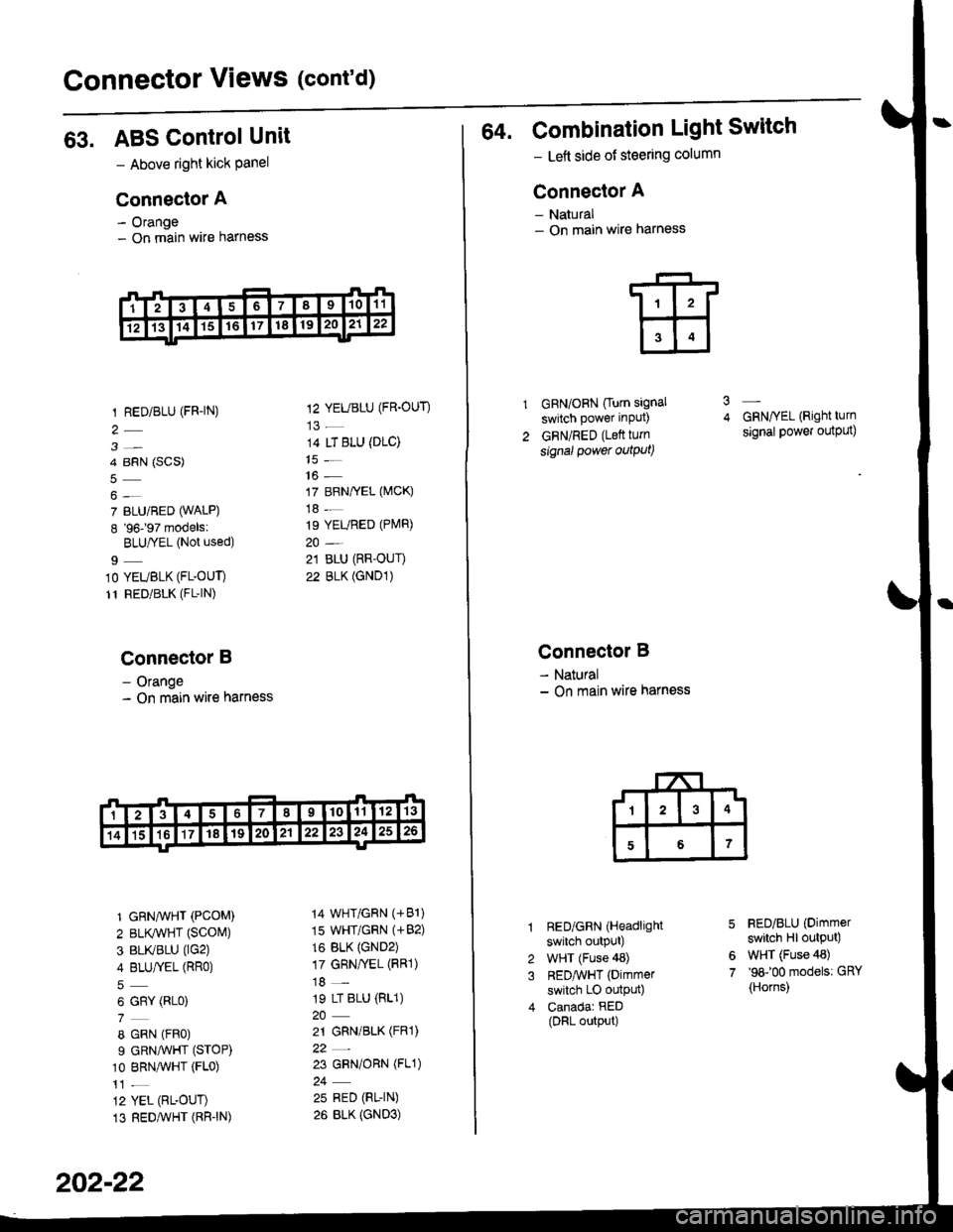
64. Combination Light Switch
- Lett side of steering column
Connector A
- Natural- On main wire harness
GRN/ORN Ourn signal
switch power input)
GRN/RED (Lett turn
signal power outqut)
3
Connector B
- Natural- On main wire harness
RED/GRN (Headlight
switch outpUt)
WHT (Fuse 48)
REDAvHT (Dimmer
switch LO outpu0
Canadar RED(DRL output)
GRN/YEL (Right turn
signal power output)
FED/BLU (Dimmer
switch Hl output)
WHT (Fuse 48)'98100 models: GRY
{Horns)
6
7