1996 HONDA CIVIC Piston ring gap
[x] Cancel search: Piston ring gapPage 49 of 2189
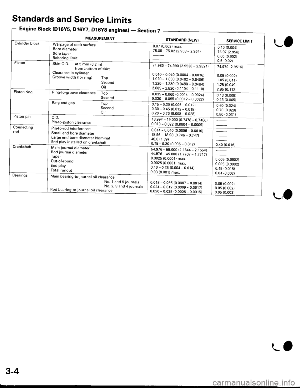
MEASUREMENT
,n7 _--
STANDAFO INEW}
0.07 10.003) max.75.00 75.02 (2.953 - 2.954)
7 4.9A0 7 4.990 t2.9520 2.95241
0.010 - 0.040 (0.0004 0.0016)1.020 - 1.030 10.0402 _ 0.0406)1.220 1.230 (0.0480 - 0.0484)2.805 - 2.820 {0.1 104 _ 0.11 tO)
0.035 - 0.060 (0.0014 0.0024)0.030 - 0.055 {0.0012 0.0022)_
0.15 0.30 {0.006 _ 0.012)0.30 - 0.45 (0.012 - 0.018)0.20 - 0.70 10.008 0.028)
18.994 - 19.000 (0.7478 _ 0.7480)0.010 - 0 0?2 lo oona -n dn^ol
SERVICE LIMIT
0.10 (0.004)
75.07 (2.956)0.05 (0.002)0.5 (0.02)
74.970 (2.9516)
0.05 (0.002)1.05 (0.041)
1.2510.049)2.85 (0.112)
0.13 {0.005)0.13 (0.005)
0.60 (0.024)
0.70 (0.028)
ljqql) _
oro to.o',ur
0.005 (0.0002)
0.005 (0.0002)
0.4510.018)0.04 (0.002)
0.05 (0.002)
0.05 {0.002)0.05 (0.002)
Cylinder blockWarpage of deck surfaceBore diameterBore taperReboring limit
Skirt O.D. at 5 mm (0.2 in)from bottom of skinClearance in cylinderGroove width {for ring) TopSecondoil
Ring to-groove clearance TopSecondRing end gapTopSecondoil
o.D.Pin-to piston clearance
Pin-to rod interferenceSmall end bore diameterLarge end bore diameter NominalEnd play installed on crankshaft
Piston
Piston ring
Piston pin
Connectingrod0.014 - 0.040 (0.0006 _ 0.ool6)18.96 - 18.98 (0.746 0.747)48.011.89)0.15 - 0.30 (0.006 - 0.012)CrankshaftMain journaldiameter
Rod iournaldiameterTaperOut of-roundEnd playTotal runout
Main bearing to-lournal o't clearance-No_ l and 5journals
_ No. 2, 3 and 4 journatsBod bearing to,journat oil ctearance
54.976 - s5.000 (2.1644 - 2.1654)44.91 6 - 45.000 1'1.17 01 _ 1.71 11 10.002510.0001) max.0.0025 (0.0001)max.
0.10 - 0.35 (0.004 0.014)0.03 (0.001) max.Bea.ings
0.018 - 0.036 (0.0007 0.0014)0.024 0.042 (0.0009 - 0.0017)0.020 - 0.038 (0.0008 _ o.oo.t5)
Standards and Service Limits
Engine Block {Dl6Y5, D16Y7, Dt6y8 enginesl - Section
L,
LO
3-4
LO
Page 50 of 2189
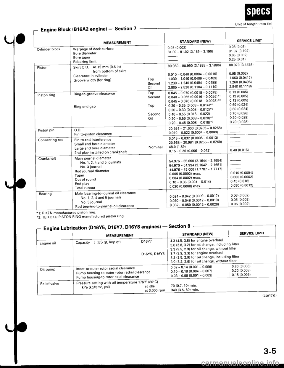
Section 7
Unlt of length: rnm ( n)
Engine Block(816A2 engine) -
MEASUREMENT
Warpage of deck surface
Bore diameterBore taperReboring limit
STANOARD {NEW)
0.05 (0.002)
8L00 81.02 (3.189 3.190)
SERVICE LIMIT
0.08 {0.03)81.07 (3.192)
0.05 (0.002)
0.25 (0.01)
Cylinder block
PistonSkin O D. At 15 mm (0.6 in)
{rom bottom of skirt
Clearance in cylinder
Groove width (for ring) ToPSecondoil
80.980 - 80.990 (3.lUUz 3. rUubl du Y/u lJ. ro/o,
I0.010 0.040 (o.ooo4 - 0.0016' 0 05 r0 002) II O3O 1.040 10.0406 - 0.04091 1 060 {0 0417) |1.230 - 1.?40 {0.0484 . 0.04881 1.260 10.04961 1'*: ?:::i?l:91'::ll:l I::::::= lPiston ringRing-to-groove clearance
Ring end gap
o.D.Pin to-piston clearance
Pin'to rod interference
Small end bore diameter
Large end bore diameterEnd play installed on crankshaft
Main journal diameterNo. 1, 2, 4 and 5 iournalsNo. 3 journal
Rod journal diameterTaperOut of roundEnd play
Total runout
Main bearing to_journal oil clearance
No. 1, 2, 4 and 5 journals
No. 3 journal
Bod bearing'to iournal oil clearance
Second
Top
Secondoil
Nominal
0.13 (0.005)
0.1310.005)0.60 (0.024)
0.60 t0.024)0.7010.028)0.70 (0.028)
,rr]q!4l
-l
u.u45 - u.u/u lu.uu ro
0.040 - 0.065 (0.0016 0.0026)*l
0.045 - 0.070 (0.0018 0.0028)*'
0.20 - 0.35 (0.008 - 0.014)*1
o.20 - 0.30 (0.008 - 0.012)*'�
0.40 0.55 (0.016 0.022)
0.20 - 0.50 (0.008 - 0.020)*'
0.20 - 0.45 (0.008 - 0.018)"
20.994 - 21.000 {0.8265 - 0.8268)
0.010 - 0.022 (0.0004 0.0009)
0.013 - 0.032 (0.0005 - 0.0013)
20.968 20.981 (0.8255 - 0.8260)
lliSlto?,o.oou o.o''r, o.rotoo'ut
Piston pin
Connecting rod
54.976 55.000 (2.1644 - 2.1654)
54.970 - 54.994 (2.1642 2.1651)
44.976 - 45.00011.'1707 - 1.1711|
0.005 (0.0002) max.0.004 (0.0002) max.0.10 0.35 (0.004 - 0.014)
0.020 (0.0008imax.
0.010 (0.0004)
0.006 (0.0002)
0.45 (0.018)
0.030 (0.0012)
Crankshaft
Eearing0.024 - 0.042 (0.0009 0.0017)
o.o3o - 0.048 {0.0012 0.0019)
0.032 - 0.050 (0.0013 - 0.0020)
0.06 (0.002)
0.06 (0.002)
0.06 (0.002)
*1: RIKEN manutactured prston rrng*2:TEIKOKU PISTON RING manufactured piston ring
gineslSection 8
(cont'd)
Engine Lubri,cation (Dl6Y5, Dl5Y7' Dl6Y8 enginesl -
MEASUREMENTSTANOARD (NEW) S€RVICE LIMIT
4.3 (4.5, 3.8)Ior engine overhaul
3.6 (3.8, 3.2) for oil change, including filter
3.3 (3.5, 2.9) for oil change, without filter
3.7 (3.9,3.3)for engine overhaul
3.3 (3.5, 2.9) for oil change, including filter
3.0 {3.2, 2.6} for oil change, without filter
0.02 - 0.14 (O.OO1 - 0.006) 0.20 {0 008)
0.10 0.18 (o.oo4 - 0.007) i 0.20 (0 008)
o 03 !.08 (qool!.oo3l _ (0 006) -
70 (0.7, 10) min.
340 (3.5,50) min
Engine oilCapacity | (US qt, lmp qt) D16Y7
D16Y5 D16Y8
lnner-to-outer rotor radial clearance
Pump housing to_outer rotor radialclearance
Pumo housrnq_to rotor a)rial clearance
Pressure setting with oil temperature 176'F (80'Ci
kPa (kgf/cm'�, PsiI at idleat 3,000 rpm
Oil pump
Relief valve
3-5
Page 120 of 2189
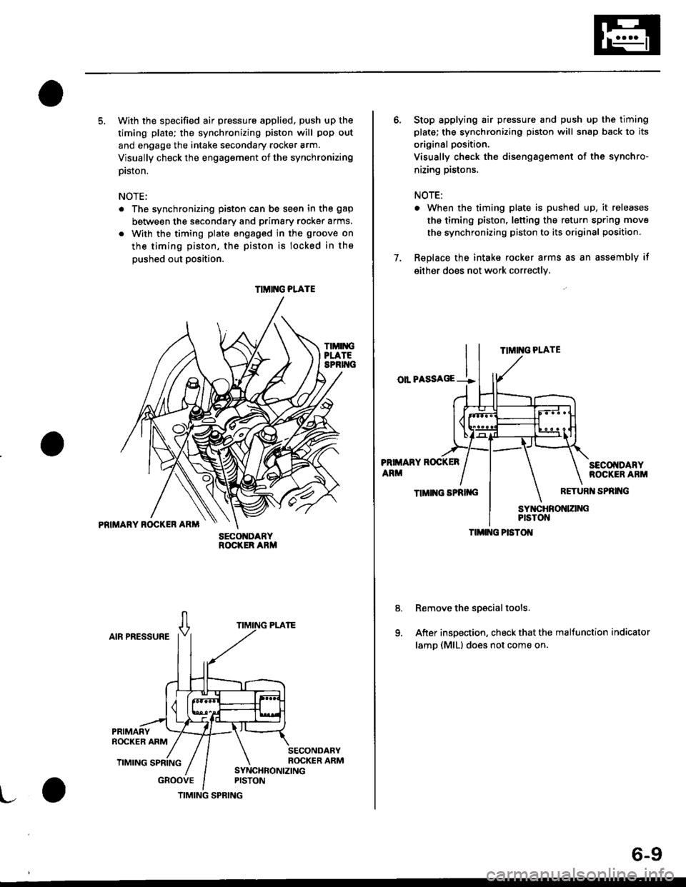
5. With the specified air pressure appli€d, push up the
timing plate; the synchronizing piston will pop out
and engage the intake secondary rocker arm.
Visually check the engagement of the synchronizing
prston.
NOTE;
The synchronizing piston can be seen in the gap
between the secondary and primary rocker arms,
With the timing plate engaged in the groove on
the timing piston, the piston is locked in the
oushed out Dosition.
TIMIiIGPLATESPRIT{C
PRIMARY ROCKER ARM
AIR PRESSURE
GROOVE
SECO DARYROCKER ARM
TIMIT{G PLATE
TIMING SPRING
6-9
6. Stop applying air pressure and push up the timing
plate; the synchronizing piston will snap back to its
original position.
Visually check the disengagement of the synchro-
nizing pistons.
NOTE:
. When the timing plate is pushed up, it releases
the timing piston, letting the return spring move
the synchronizing piston to its original position.
7. Replace the intake rocker arms as an assembly if
either does not work correctly,
TIMING PLATE
oll PASSAGE --!
PRIMARY ROCKER
ARMSECOI{DARYROCKER ARM
TIMII{G SPRII{GRETURI{ SPRING
Remove the spscial tools.
After inspection, check that the malfunction indicator
lamp (MlLl does not come on.
TIMI G PISTOI{
Page 198 of 2189
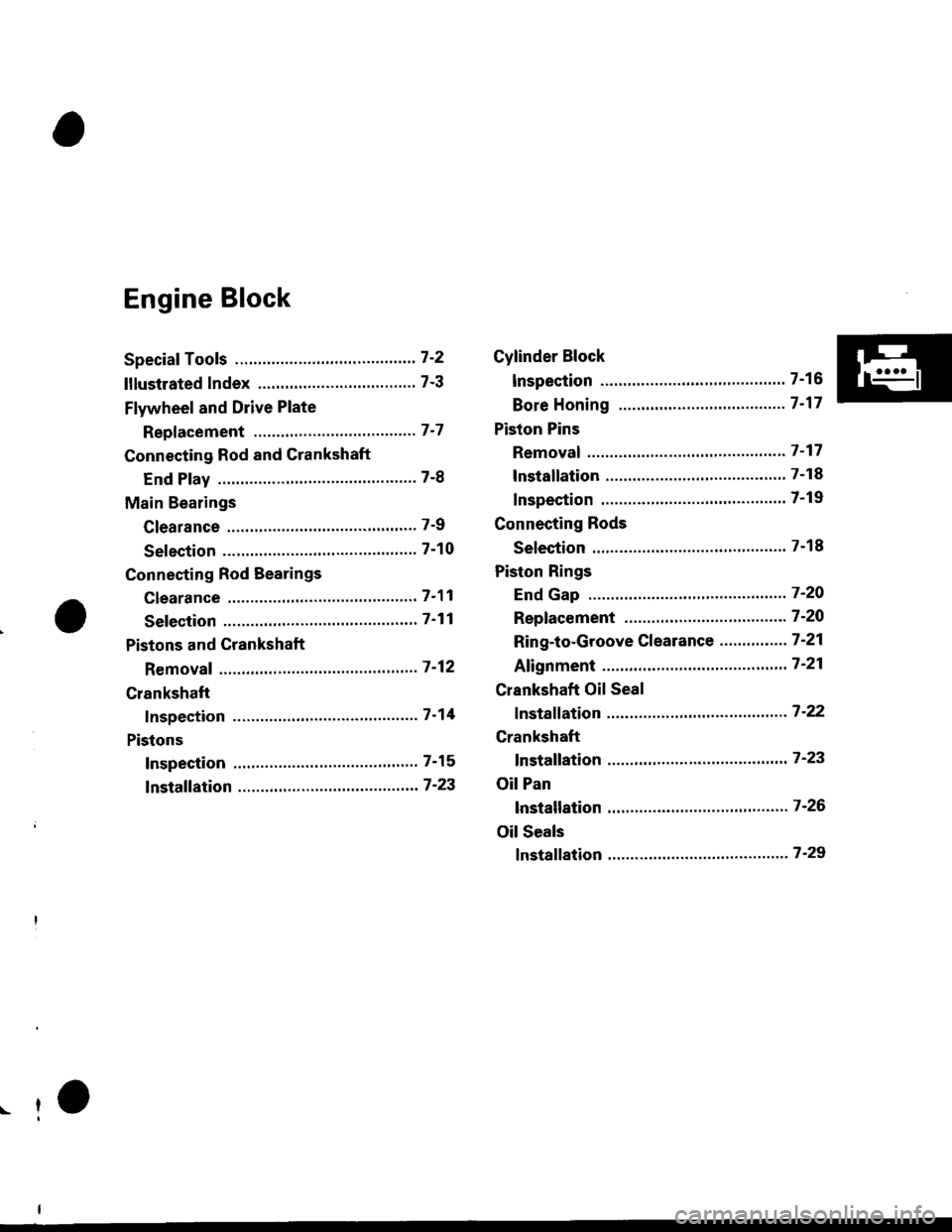
Engine Block
Speciaf Tools ..........." 7-2
lllustlated Index ...................."..'.......... 7-3
Flywheel and Drive Plate
Repf acement """'.' 7-7
Connecting Rod and Crankshaft
End Play ..........."....7-8
Main Bearings
Clearance ............... 7-9
Selection ................7-10
Connecting Rod Bearings
clearance ....'.......... 7-11
Selection ................ 7-11
Pistons and Crankshaft
Removaf ................. 7 -12
Crankshaft
Inspection ."".........7-14
Pistons
Inspection ......"'.....7-15
fnstaffation .............7-23
Cylinder Block
lnspec'tion ..............7-16
Bore Honing ..........7-17
Piston Pins
Removal ...,...........'.7-17
lnstallation .............7-18
Inspection .'............7-19
Connecting Rods
Selection ................7-18
Piston Rings
End Gap ..........".."' 7'2O
Repfacement .........7-2O
Ring-to-Groove Clearance ...........'.'. 7 -21
Afignment .......""'.. 7'21
Crankshaft Oil Seal
fnstaffation .............7-22
Crankshaft
fnstaffation ..-.-..'.".' 7'23
Oil Pan
lnstallation .............7-26
Oil Seals
fnstaffation ....""""' 7-29
r-f
Page 217 of 2189
Piston Rings
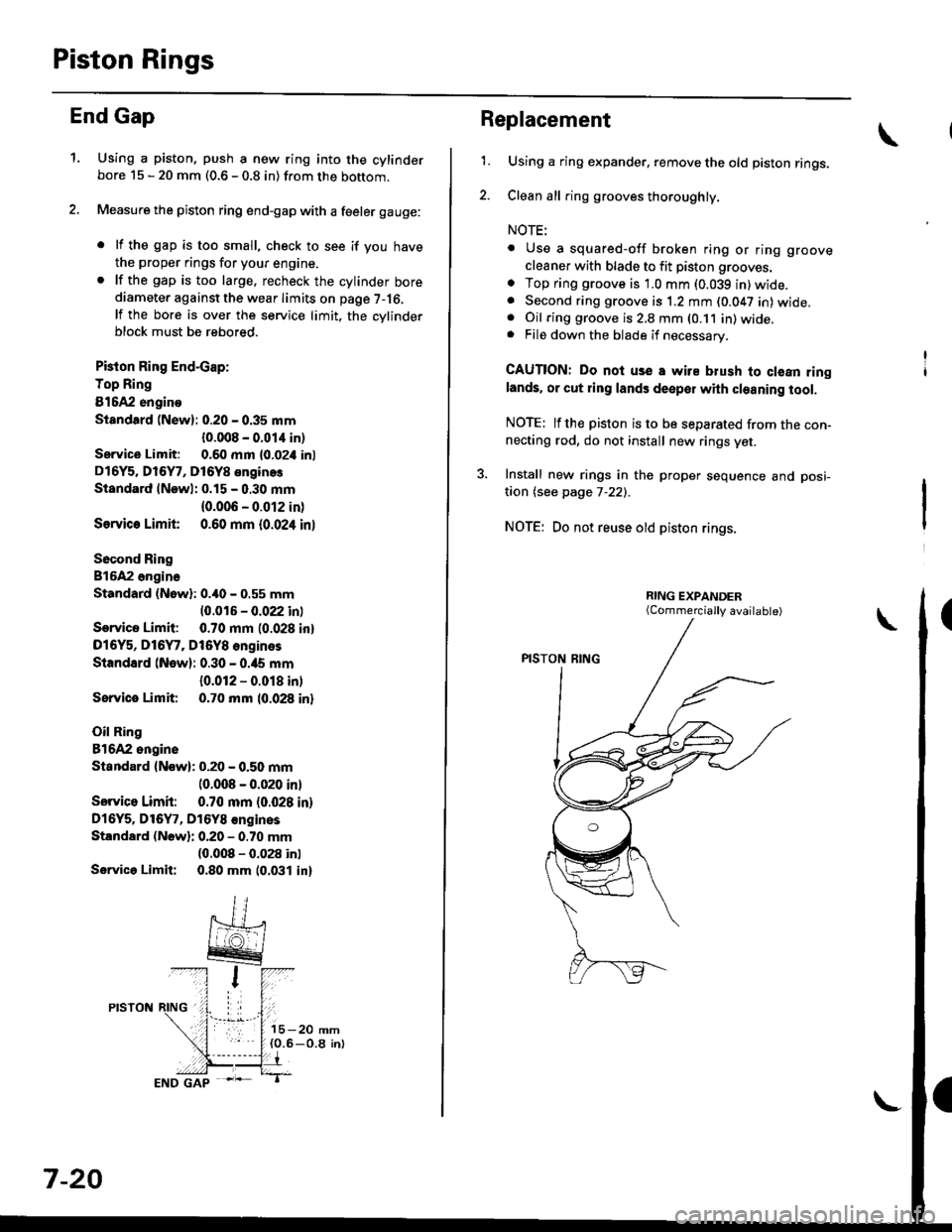
End Gap
1.Using a piston, push a new ring into the cylinderbore 15 - 20 mm (0.6 - 0.8 in) from the bottom.
Measure the piston ring end-gap with a feeler gauge:
. lf the gap is too small, check to see if you have
the proper rings for your engine.. lf the gap is too large. recheck the cylinder borediameter against the wear limits on page 7-16,
lf the bore is over the service limit, the cvlinderblock must be rebored.
Pkton Ring End-cap:
Top Ring
81642 engino
Siandtrd (New): 0.20 - 0.35 mm
{0.008 - 0.01,1 in)
Service Limit: 0.60 mm l0-02i1 inl
D16Y5. Dl6Y7, D16Y8 enginos
Standard lNewl: 0.15 - 0.30 mm
{0.006 - 0.012 in)
Ssrvic€ Limit 0.60 mm {0.024 inl
Socond Ring
816A2 ongina
Standard (Nowl: 0.40 - 0.55 mm
10.016 - 0.022 inl
Service Limit: 0.70 mm (0.028 inl
D16Y5, D16Y7, Dt6Y8 engines
Standard (New): 0.30 - 0.ia5 mm
{0.012 - 0.018 in)
Sorvice Limit 0.70 mm 10.028 inl
Oil Ring
81642 ongine
Standard {Now): 0.20 - 0.50 mm(0.008 - 0.020 inl
Sorvico Limit: 0.70 mm (0.028 in)
Dl6Y5. Dl6Y7, D16Y8 €nginos
Standard (Nowli 0.20 - 0.70 mm(0.008 - 0.028 inl
Servica Limit: 0.80 mm 10.031 in)
7-20
Replacement
1.Using a ring expander. remove the old piston rings.
Clean all ring grooves thoroughly.
NOTE:
. Use a squared-off broken ring or ring groove
cleaner with blade to fit piston grooves.
o Top ring groove is 1.0 mm (0.039 in)wide.. Second ring groove is 1.2 mm (0.047 in) wide.. Oil ring groove is 2,8 mm (0.11 in) wide.. File down the blade if necessary.
CAUTION: Do noi use a wire blush to clean ringlands. or cut ring lands deepol with cleaning tool.
NOTE: lfthe piston is to be separated from the con-necting rod, do not install new rings yet.
3. Install new rings in the proper sequence and posi-
taon (see page 7-22).
NOTE: Do not reuse old piston rings.
(Commercially available)
Page 219 of 2189

Piston RingsCrankshaft Oil Seal
Alignment (cont'dl
TOP RING ---.>
SECOND RING >
MARK
,a-)
/\_4
o,.r^o( qffi<--sPACER
\Z-.
v
Rotate the rings in their grooves to make sure theydo not bind.
Position the ring end gaps as shown:
DO NOT position any ring gapat piston thrust surfaces.
DO NOT position any ring gapin line with the piston pin hole.OIL RING GAP
SECOND RING GAP
Approx.90
TOP RING GAP
7-22
Installation
The seal surface on the block should be dry.Apply a light coat of oil to the c.ankshaft and tothe lip of the seal.
1. Drive the crankshaft oil seal squarely into the right
side cover using the special tools.
HANDLE DRIVER07749 0010000
seal with thepan number sidefacing out.
Confirm that the clearance is equal all the way
around with a feeler gauge.
Clearance:0.5 - 0.8 mm (0.02 - 0.03 inl
NOTE: Refer to page 8-14 for installation of the oilpumo side crankshaft oil seal.
,(
\
Page 1015 of 2189
1.
7.
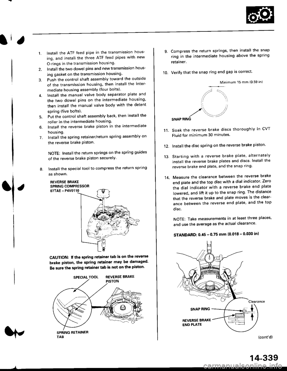
lnstall the ATF feed pipe in the transmission hous-
ing, and install the three ATF feed pipes with new
O-rings in the transmission housing,
Install the two dowel pins and new transmission hous-
ing gasket on the transmission housing.
Push the control shaft assembly toward the outside
of the transmission housing, then install the inter-
mediate housing assembly (four bolts).
lnstall the manual valve body separator plate and
the two dowel pins on the intermediate housing,
then install the rnanual valve body with the detent
spring (five bolts).
Put the control shaft assembly back, then install the
roller in the intermediate housing.
lnstall the reverse brake piston in the intermediate
housing.
Install the spring retainer/return spring assembly on
the reverse brake Piston.
NOTE: Installthe return springs on the spring guides
of the reverse brake piston securely
tnstall the special tool to compress the return spring
as shown.
REVERSE BRAKESPRING COMPRESSOR07TAE - P4V0110
6.
L
1
CAUTION: lf the spring retainer tab is on the reverse
brakc piston, the spring rstainer may be damaged'
Be sure the spring retainer tab is not on the piston'
rp
SPECIALTOOL REVERSEBRAKE
-^
14-339
10.
9.
14.
Compress the return springs, then install the snap
ring in the intermediate housing above the spring
retainer.
Verify that the snap ring end gap is correct'
Mini
/,,- '-t,,,,.
// \i/ ',r
'1 ,
.r' //'/. .-J?RINGSNAP
mum 15 mm 10.59 in)
Soak the reverse brake discs thoroughly in CVT
Fluid for minimum 30 minutes.
Installthe disc spring on the reverse brake piston'
Starting with a reverse brake plate, alternately
install the reverse brake plates and discs lnstall the
reverse brake end plate, and the snap ring'
Measure the clearance between the reverse brake
end plate and the top disc with a dial indicator' Zero
the dial indicator with a reverse brake end plate
lowered, and lift it up to the snap ring The distance
that the reverse brake and plate moves is the clear-
ance between the reverse end plate, and the top
disc.
NOTE: Take measurements in at least three places'
and use the average as the actual clearance'
STANDARD: 0.45 - 0.75 mm (0.018 - 0'030 in)
{cont'd)
11.
12.
13.