1996 CHRYSLER VOYAGER wheel bolt torque
[x] Cancel search: wheel bolt torquePage 1785 of 1938
REAR HVAC LOUVER AND BEZEL
REMOVAL
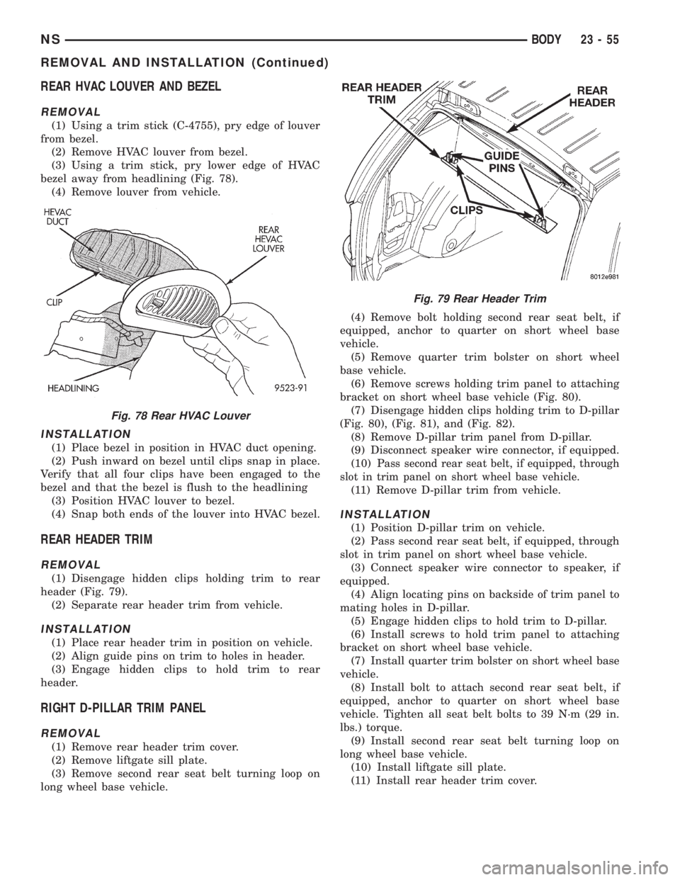
(1) Using a trim stick (C-4755), pry edge of louver
from bezel.
(2) Remove HVAC louver from bezel.
(3) Using a trim stick, pry lower edge of HVAC
bezel away from headlining (Fig. 78).
(4) Remove louver from vehicle.
INSTALLATION
(1) Place bezel in position in HVAC duct opening.
(2) Push inward on bezel until clips snap in place.
Verify that all four clips have been engaged to the
bezel and that the bezel is flush to the headlining
(3) Position HVAC louver to bezel.
(4) Snap both ends of the louver into HVAC bezel.
REAR HEADER TRIM
REMOVAL
(1) Disengage hidden clips holding trim to rear
header (Fig. 79).
(2) Separate rear header trim from vehicle.
INSTALLATION
(1) Place rear header trim in position on vehicle.
(2) Align guide pins on trim to holes in header.
(3) Engage hidden clips to hold trim to rear
header.
RIGHT D-PILLAR TRIM PANEL
REMOVAL
(1) Remove rear header trim cover.
(2) Remove liftgate sill plate.
(3) Remove second rear seat belt turning loop on
long wheel base vehicle.(4) Remove bolt holding second rear seat belt, if
equipped, anchor to quarter on short wheel base
vehicle.
(5) Remove quarter trim bolster on short wheel
base vehicle.
(6) Remove screws holding trim panel to attaching
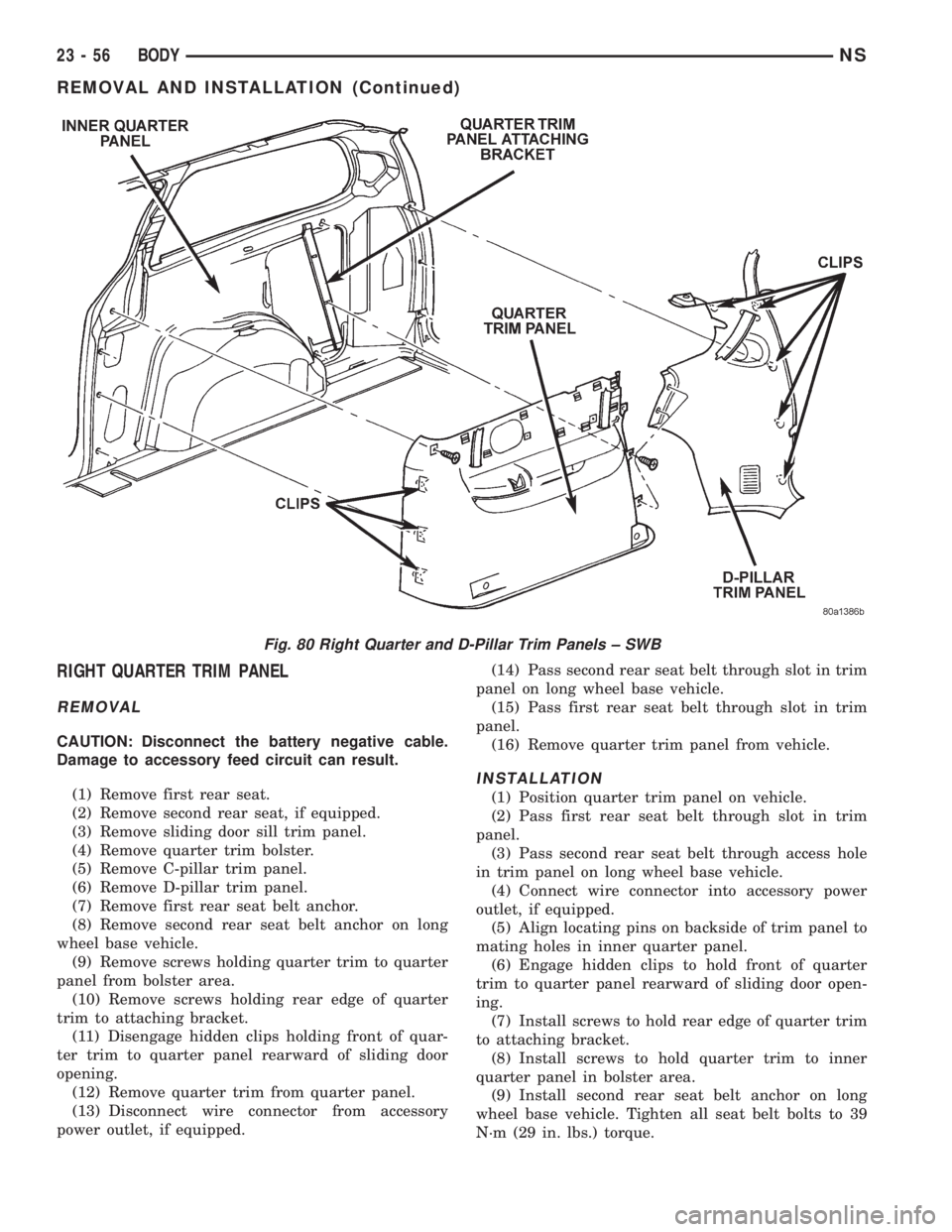
bracket on short wheel base vehicle (Fig. 80).
(7) Disengage hidden clips holding trim to D-pillar
(Fig. 80), (Fig. 81), and (Fig. 82).
(8) Remove D-pillar trim panel from D-pillar.
(9) Disconnect speaker wire connector, if equipped.
(10) P
ass second rear seat belt, if equipped, through
slot in trim panel on short wheel base vehicle.
(11) Remove D-pillar trim from vehicle.
INSTALLATION
(1) Position D-pillar trim on vehicle.
(2) Pass second rear seat belt, if equipped, through
slot in trim panel on short wheel base vehicle.
(3) Connect speaker wire connector to speaker, if
equipped.
(4) Align locating pins on backside of trim panel to
mating holes in D-pillar.
(5) Engage hidden clips to hold trim to D-pillar.
(6) Install screws to hold trim panel to attaching
bracket on short wheel base vehicle.
(7) Install quarter trim bolster on short wheel base
vehicle.
(8) Install bolt to attach second rear seat belt, if
equipped, anchor to quarter on short wheel base
vehicle. Tighten all seat belt bolts to 39 N´m (29 in.
lbs.) torque.
(9) Install second rear seat belt turning loop on
long wheel base vehicle.
(10) Install liftgate sill plate.
(11) Install rear header trim cover.
Fig. 78 Rear HVAC Louver
Fig. 79 Rear Header Trim
NSBODY 23 - 55
REMOVAL AND INSTALLATION (Continued)
Page 1786 of 1938
RIGHT QUARTER TRIM PANEL
REMOVAL
CAUTION: Disconnect the battery negative cable.
Damage to accessory feed circuit can result.
(1) Remove first rear seat.
(2) Remove second rear seat, if equipped.
(3) Remove sliding door sill trim panel.
(4) Remove quarter trim bolster.
(5) Remove C-pillar trim panel.
(6) Remove D-pillar trim panel.
(7) Remove first rear seat belt anchor.
(8) Remove second rear seat belt anchor on long
wheel base vehicle.
(9) Remove screws holding quarter trim to quarter
panel from bolster area.
(10) Remove screws holding rear edge of quarter
trim to attaching bracket.
(11) Disengage hidden clips holding front of quar-
ter trim to quarter panel rearward of sliding door
opening.
(12) Remove quarter trim from quarter panel.
(13) Disconnect wire connector from accessory
power outlet, if equipped.(14) Pass second rear seat belt through slot in trim
panel on long wheel base vehicle.
(15) Pass first rear seat belt through slot in trim
panel.
(16) Remove quarter trim panel from vehicle.
INSTALLATION
(1) Position quarter trim panel on vehicle.
(2) Pass first rear seat belt through slot in trim
panel.
(3) Pass second rear seat belt through access hole
in trim panel on long wheel base vehicle.
(4) Connect wire connector into accessory power
outlet, if equipped.
(5) Align locating pins on backside of trim panel to
mating holes in inner quarter panel.
(6) Engage hidden clips to hold front of quarter
trim to quarter panel rearward of sliding door open-
ing.
(7) Install screws to hold rear edge of quarter trim
to attaching bracket.
(8) Install screws to hold quarter trim to inner
quarter panel in bolster area.
(9) Install second rear seat belt anchor on long
wheel base vehicle. Tighten all seat belt bolts to 39
N´m (29 in. lbs.) torque.
Fig. 80 Right Quarter and D-Pillar Trim Panels ± SWB
23 - 56 BODYNS
REMOVAL AND INSTALLATION (Continued)
Page 1791 of 1938
SEAT BELT LEFT FIRST REAR OUTBOARD ± LWB
THREE DOOR
REMOVAL
(1) Remove first and second rear seats. Refer to
Owner's manual for proper procedures.
(2) Remove shoulder harness height adjuster knob
by pulling it straight away from adjuster.
(3) Slide floor anchor cover from over the anchor
bolt.
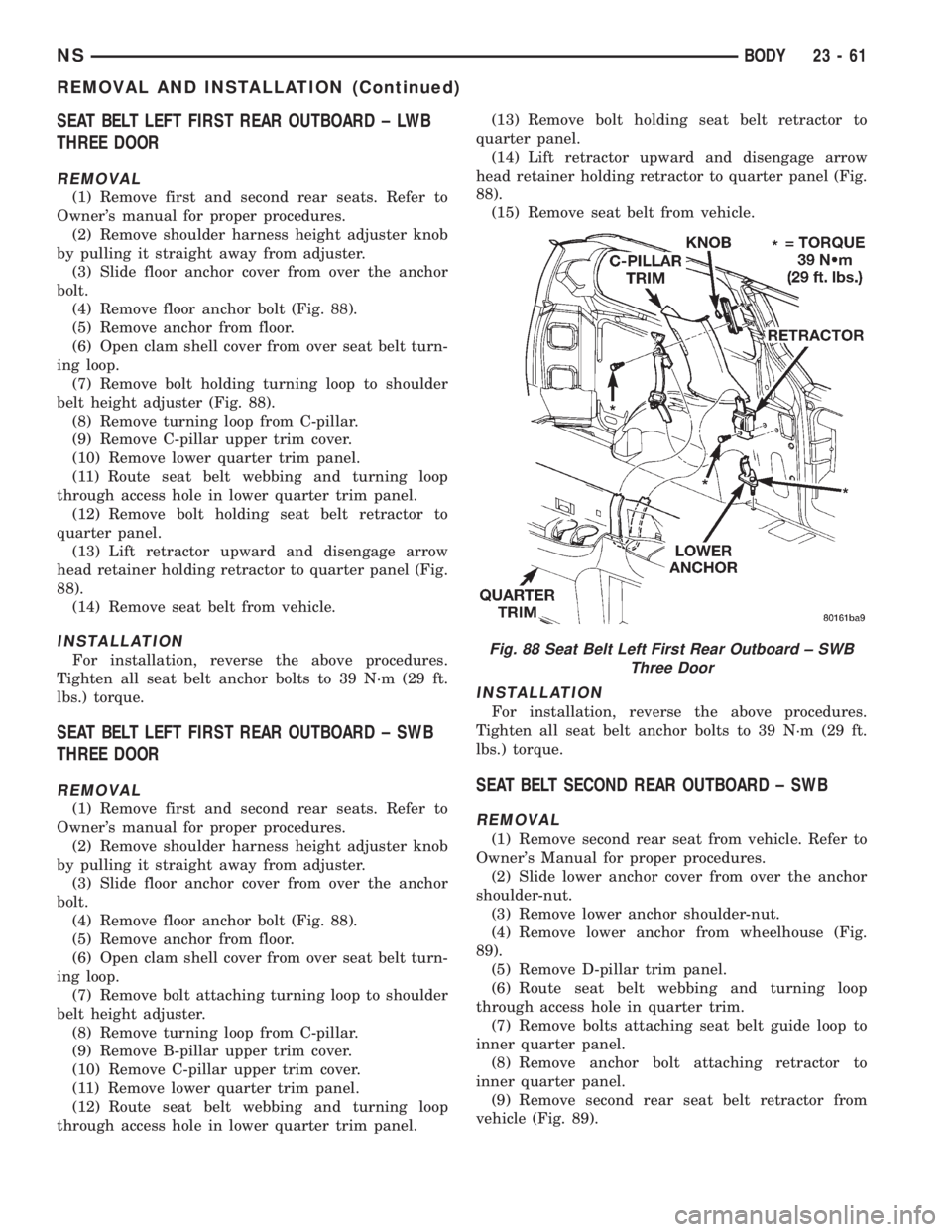
(4) Remove floor anchor bolt (Fig. 88).
(5) Remove anchor from floor.
(6) Open clam shell cover from over seat belt turn-
ing loop.
(7) Remove bolt holding turning loop to shoulder
belt height adjuster (Fig. 88).
(8) Remove turning loop from C-pillar.
(9) Remove C-pillar upper trim cover.
(10) Remove lower quarter trim panel.
(11) Route seat belt webbing and turning loop
through access hole in lower quarter trim panel.
(12) Remove bolt holding seat belt retractor to
quarter panel.
(13) Lift retractor upward and disengage arrow
head retainer holding retractor to quarter panel (Fig.
88).
(14) Remove seat belt from vehicle.
INSTALLATION
For installation, reverse the above procedures.
Tighten all seat belt anchor bolts to 39 N´m (29 ft.
lbs.) torque.
SEAT BELT LEFT FIRST REAR OUTBOARD ± SWB
THREE DOOR
REMOVAL
(1) Remove first and second rear seats. Refer to
Owner's manual for proper procedures.
(2) Remove shoulder harness height adjuster knob
by pulling it straight away from adjuster.
(3) Slide floor anchor cover from over the anchor
bolt.
(4) Remove floor anchor bolt (Fig. 88).
(5) Remove anchor from floor.
(6) Open clam shell cover from over seat belt turn-
ing loop.
(7) Remove bolt attaching turning loop to shoulder
belt height adjuster.
(8) Remove turning loop from C-pillar.
(9) Remove B-pillar upper trim cover.
(10) Remove C-pillar upper trim cover.
(11) Remove lower quarter trim panel.
(12) Route seat belt webbing and turning loop
through access hole in lower quarter trim panel.(13) Remove bolt holding seat belt retractor to
quarter panel.
(14) Lift retractor upward and disengage arrow
head retainer holding retractor to quarter panel (Fig.
88).
(15) Remove seat belt from vehicle.
INSTALLATION
For installation, reverse the above procedures.
Tighten all seat belt anchor bolts to 39 N´m (29 ft.
lbs.) torque.
SEAT BELT SECOND REAR OUTBOARD ± SWB
REMOVAL
(1) Remove second rear seat from vehicle. Refer to
Owner's Manual for proper procedures.
(2) Slide lower anchor cover from over the anchor
shoulder-nut.
(3) Remove lower anchor shoulder-nut.
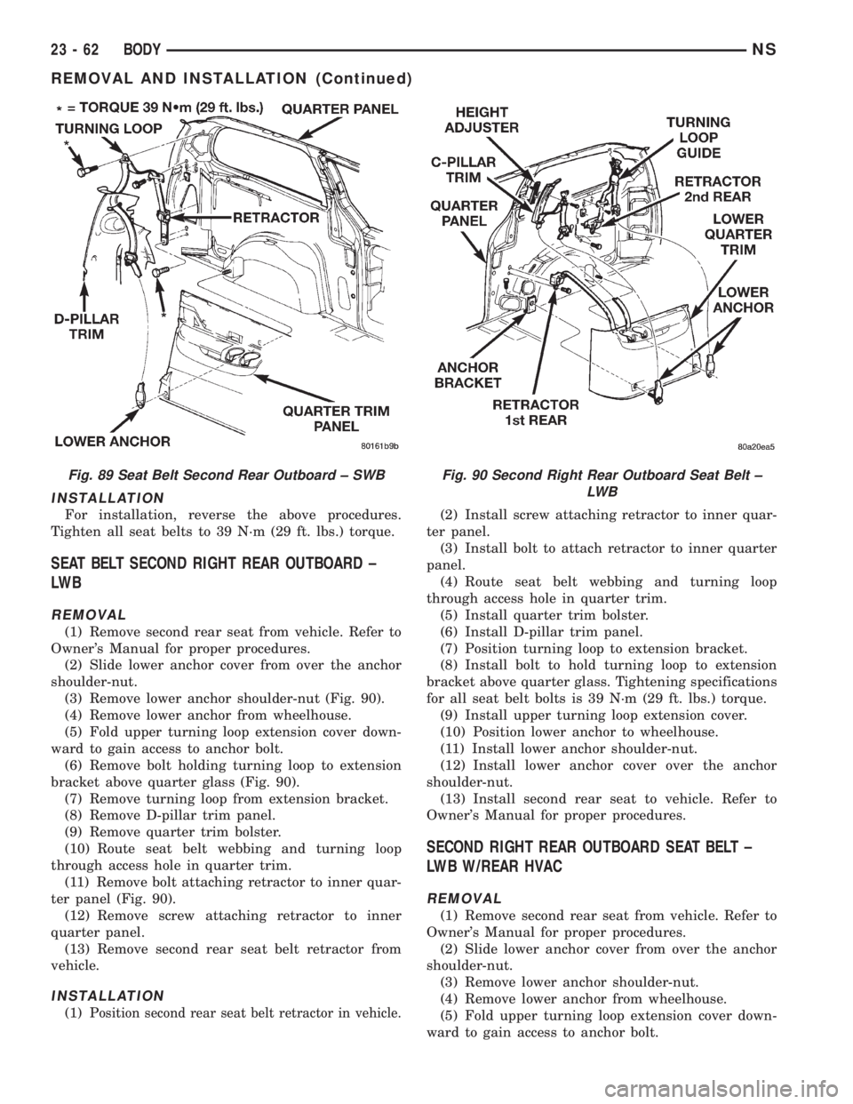
(4) Remove lower anchor from wheelhouse (Fig.
89).
(5) Remove D-pillar trim panel.
(6) Route seat belt webbing and turning loop
through access hole in quarter trim.
(7) Remove bolts attaching seat belt guide loop to
inner quarter panel.
(8) Remove anchor bolt attaching retractor to
inner quarter panel.
(9) Remove second rear seat belt retractor from
vehicle (Fig. 89).
Fig. 88 Seat Belt Left First Rear Outboard ± SWB
Three Door
NSBODY 23 - 61
REMOVAL AND INSTALLATION (Continued)
Page 1792 of 1938
INSTALLATION
For installation, reverse the above procedures.
Tighten all seat belts to 39 N´m (29 ft. lbs.) torque.
SEAT BELT SECOND RIGHT REAR OUTBOARD ±
LW B
REMOVAL
(1) Remove second rear seat from vehicle. Refer to
Owner's Manual for proper procedures.
(2) Slide lower anchor cover from over the anchor
shoulder-nut.
(3) Remove lower anchor shoulder-nut (Fig. 90).
(4) Remove lower anchor from wheelhouse.
(5) Fold upper turning loop extension cover down-
ward to gain access to anchor bolt.
(6) Remove bolt holding turning loop to extension
bracket above quarter glass (Fig. 90).
(7) Remove turning loop from extension bracket.
(8) Remove D-pillar trim panel.
(9) Remove quarter trim bolster.
(10) Route seat belt webbing and turning loop
through access hole in quarter trim.
(11) Remove bolt attaching retractor to inner quar-
ter panel (Fig. 90).
(12) Remove screw attaching retractor to inner
quarter panel.
(13) Remove second rear seat belt retractor from
vehicle.
INSTALLATION
(1) Position second rear seat belt retractor in vehicle.
(2) Install screw attaching retractor to inner quar-
ter panel.
(3) Install bolt to attach retractor to inner quarter
panel.
(4) Route seat belt webbing and turning loop
through access hole in quarter trim.
(5) Install quarter trim bolster.
(6) Install D-pillar trim panel.
(7) Position turning loop to extension bracket.
(8) Install bolt to hold turning loop to extension
bracket above quarter glass. Tightening specifications
for all seat belt bolts is 39 N´m (29 ft. lbs.) torque.
(9) Install upper turning loop extension cover.
(10) Position lower anchor to wheelhouse.
(11) Install lower anchor shoulder-nut.
(12) Install lower anchor cover over the anchor
shoulder-nut.
(13) Install second rear seat to vehicle. Refer to
Owner's Manual for proper procedures.
SECOND RIGHT REAR OUTBOARD SEAT BELT ±
LWB W/REAR HVAC
REMOVAL
(1) Remove second rear seat from vehicle. Refer to
Owner's Manual for proper procedures.
(2) Slide lower anchor cover from over the anchor
shoulder-nut.
(3) Remove lower anchor shoulder-nut.
(4) Remove lower anchor from wheelhouse.
(5) Fold upper turning loop extension cover down-
ward to gain access to anchor bolt.
Fig. 89 Seat Belt Second Rear Outboard ± SWBFig. 90 Second Right Rear Outboard Seat Belt ±
LW B
23 - 62 BODYNS
REMOVAL AND INSTALLATION (Continued)
Page 1861 of 1938
CAUTION: Do not damage the evaporator insulation
liner during installation.
(3) Carefully install the evaporator and expansion
valve straight into the unit. Do not scratch the seal-
ing surfaces with the plumbing extension tube pilots.
(4) Determine the amount of old refrigerant oil
drained from the evaporator. Add this amount (of
clean refrigerant oil) back into the system.
(5) Carefully align the expansion valve onto the
pilot tubes of the plumbing extension (do not scratch
the sealing surface). Install the bolt through the
plumbing plate into the unit sealing plate. Tighten
bolts to 2363 N´m (200630 inch pounds) torque.
(6) Install evaporator cover and blower scroll.
(7) Install quarter trim panel, evacuate/charge sys-
tem, and perform the performance test.
REAR AIR CONDITIONING LINES
WARNING: THE REFRIGERATION SYSTEM MUST
BE COMPLETELY EMPTY BEFORE PROCEEDING
WITH THIS OPERATION.
REMOVAL
(1) Hoist vehicle
(2) Remove compression fittings to the suction and
liquid lines located on the right, outboard side of the
underbody, rearward of the front crossmember. (Fig.
2)
(3) remove (1) bolt securing a/c lines to block
located on the right, outboard side of the underbody,
rearward of the rear wheel and tire. (Fig. 5)
(4) Remove (3) straps securing underbody lines.
(Fig. 1)
(5) Separate and remove a/c lines from vehicle.
INSTALLATION
(1) Before installation, replace all O-rings and gas-
kets. Coat all sealing surfaces with approved wax-
free refrigerant oil. Then, reverse the above
procedures.
(2) Evacuate and recharge system.
REAR HEATER A/C AIR OUTLETS
REMOVAL
Separate barrel from bezel by pulling outward.
INSTALLATION
For installation, push the outlet firmly into the
opening until it locks into place.
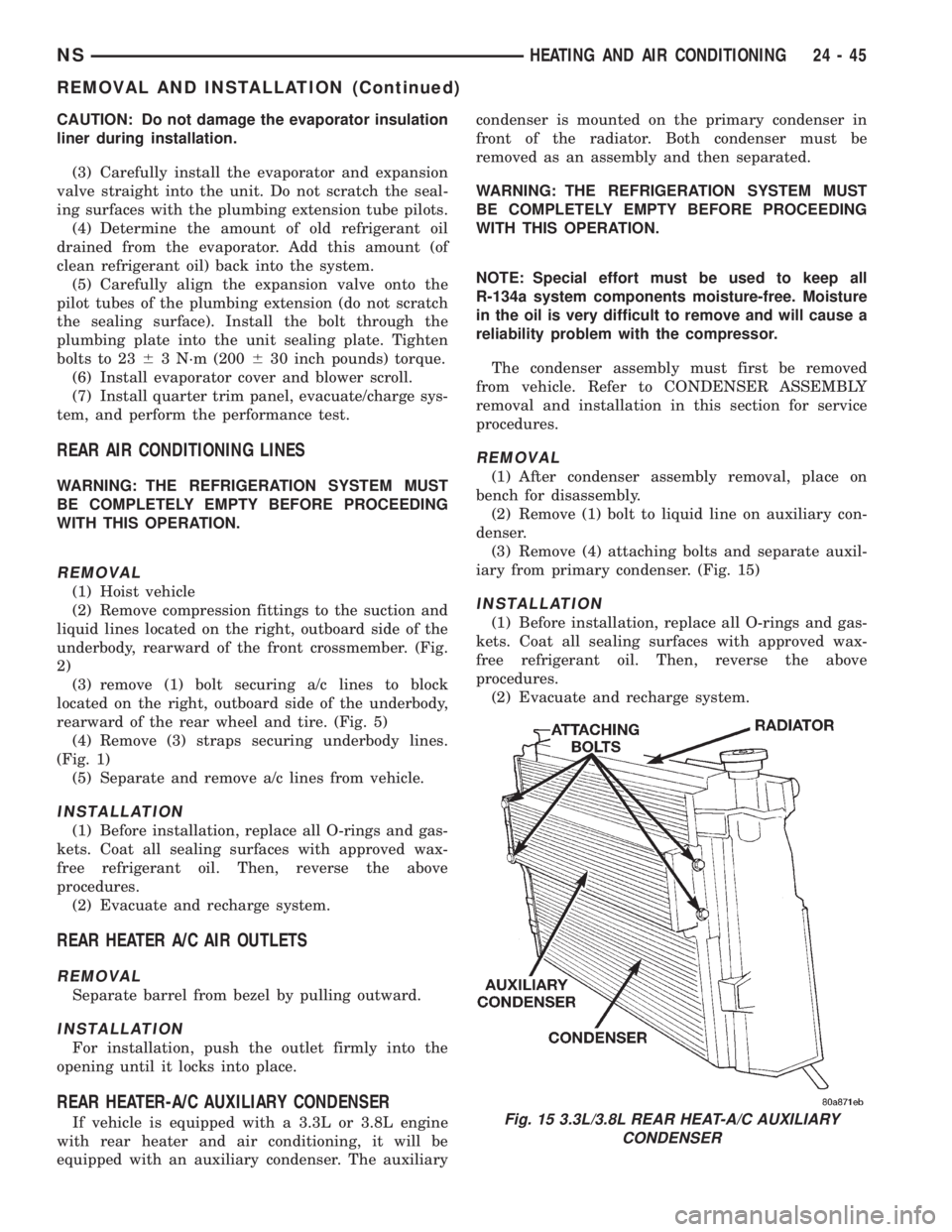
REAR HEATER-A/C AUXILIARY CONDENSER
If vehicle is equipped with a 3.3L or 3.8L engine
with rear heater and air conditioning, it will be
equipped with an auxiliary condenser. The auxiliarycondenser is mounted on the primary condenser in
front of the radiator. Both condenser must be
removed as an assembly and then separated.
WARNING: THE REFRIGERATION SYSTEM MUST
BE COMPLETELY EMPTY BEFORE PROCEEDING
WITH THIS OPERATION.
NOTE: Special effort must be used to keep all
R-134a system components moisture-free. Moisture
in the oil is very difficult to remove and will cause a
reliability problem with the compressor.
The condenser assembly must first be removed
from vehicle. Refer to CONDENSER ASSEMBLY
removal and installation in this section for service
procedures.
REMOVAL
(1) After condenser assembly removal, place on
bench for disassembly.
(2) Remove (1) bolt to liquid line on auxiliary con-
denser.
(3) Remove (4) attaching bolts and separate auxil-
iary from primary condenser. (Fig. 15)
INSTALLATION
(1) Before installation, replace all O-rings and gas-
kets. Coat all sealing surfaces with approved wax-
free refrigerant oil. Then, reverse the above
procedures.
(2) Evacuate and recharge system.
Fig. 15 3.3L/3.8L REAR HEAT-A/C AUXILIARY
CONDENSER
NSHEATING AND AIR CONDITIONING 24 - 45
REMOVAL AND INSTALLATION (Continued)