1996 CHRYSLER VOYAGER wheel bolt torque
[x] Cancel search: wheel bolt torquePage 1432 of 1938
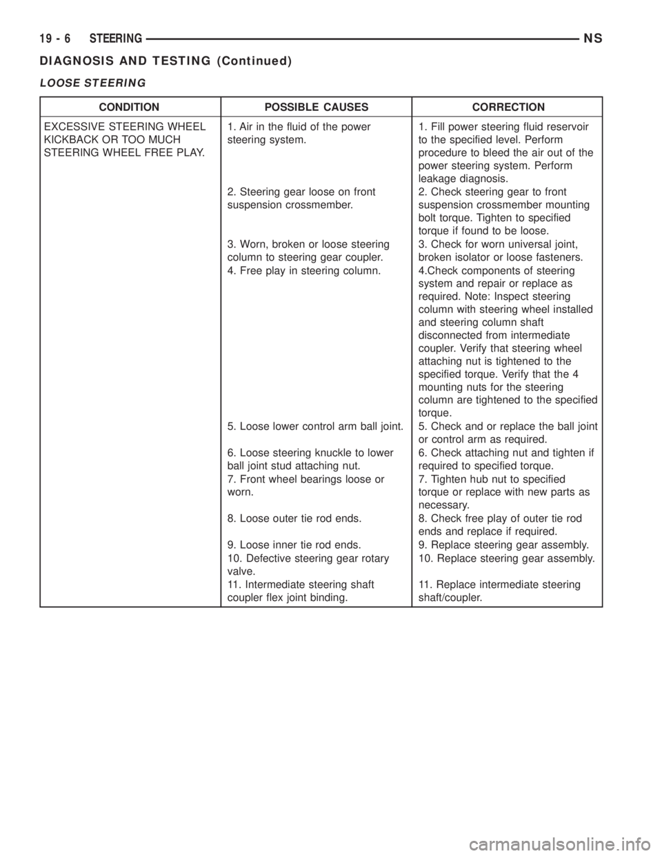
LOOSE STEERING
CONDITION POSSIBLE CAUSES CORRECTION
EXCESSIVE STEERING WHEEL
KICKBACK OR TOO MUCH
STEERING WHEEL FREE PLAY.1. Air in the fluid of the power
steering system.1. Fill power steering fluid reservoir
to the specified level. Perform
procedure to bleed the air out of the
power steering system. Perform
leakage diagnosis.
2. Steering gear loose on front
suspension crossmember.2. Check steering gear to front
suspension crossmember mounting
bolt torque. Tighten to specified
torque if found to be loose.
3. Worn, broken or loose steering
column to steering gear coupler.3. Check for worn universal joint,
broken isolator or loose fasteners.
4. Free play in steering column. 4.Check components of steering
system and repair or replace as
required. Note: Inspect steering
column with steering wheel installed
and steering column shaft
disconnected from intermediate
coupler. Verify that steering wheel
attaching nut is tightened to the
specified torque. Verify that the 4
mounting nuts for the steering
column are tightened to the specified
torque.
5. Loose lower control arm ball joint. 5. Check and or replace the ball joint
or control arm as required.
6. Loose steering knuckle to lower
ball joint stud attaching nut.6. Check attaching nut and tighten if
required to specified torque.
7. Front wheel bearings loose or
worn.7. Tighten hub nut to specified
torque or replace with new parts as
necessary.
8. Loose outer tie rod ends. 8. Check free play of outer tie rod
ends and replace if required.
9. Loose inner tie rod ends. 9. Replace steering gear assembly.
10. Defective steering gear rotary
valve.10. Replace steering gear assembly.
11. Intermediate steering shaft
coupler flex joint binding.11. Replace intermediate steering
shaft/coupler.
19 - 6 STEERINGNS
DIAGNOSIS AND TESTING (Continued)
Page 1439 of 1938
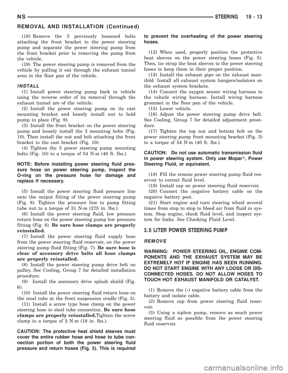
(18) Remove the 3 previously loosened bolts
attaching the front bracket to the power steering
pump and separate the power steering pump from
the front bracket prior to removing the pump from
the vehicle.
(19) The power steering pump is removed from the
vehicle by pulling it out through the exhaust tunnel
area in the floor pan of the vehicle.
INSTALL
(1) Install power steering pump back in vehicle
using the reverse order of its removal through the
exhaust tunnel are of the vehicle.
(2) Install the power steering pump on its cast
mounting bracket and loosely install nut to hold
pump in place (Fig. 9).
(3) Install the front bracket on the power steering
pump and loosely install the 3 mounting bolts (Fig.
10). Then install the nut and bolt attaching the front
bracket to the cast bracket (Fig. 10).
(4) Tighten the 3 power steering pump mounting
bolts (Fig. 10) to a torque of 54 N´m (40 ft. lbs.).
NOTE: Before installing power steering fluid pres-
sure hose on power steering pump, inspect the
O-ring on the pressure hose for damage and
replace if necessary.
(5) Install the power steering fluid pressure line
onto the output fitting of the power steering pump
(Fig. 8). Tighten the pressure line to pump fitting
tube nut to a torque of 31 N´m (275 in. lbs.).
(6) Install the power steering fluid, low pressure
return hose on the power steering pump low pressure
fitting (Fig. 8).Be sure hose clamps are properly
reinstalled.
(7) Install the power steering fluid supply hose
from the power steering fluid reservoir, on the power
steering pump fluid fitting (Fig. 7).Be sure hose is
clear of accessory drive belts all hose clamps
are properly reinstalled.
(8) Install the power steering pump drive belt on
pulley. See Cooling, Group 7 for detailed installation
procedure.
(9) Install the accessory drive splash shield (Fig.
6).
(10) Install the power steering fluid return hose on
the steel tube at the front suspension cradle (Fig. 5).
(11) Install a screw type hose clamp on the power
steering hose to steel tube connection.Be sure hose
clamps are properly reinstalled.Tighten the screw
clamp to a torque of 2 N´m (18 in. lbs.).
CAUTION: The protective heat shield sleeves must
cover the entire rubber hose and hose to tube con-
nection portion of both the power steering fluid
pressure and return hoses (Fig. 5). This is requiredto prevent the overheating of the power steering
hoses.
(12) When used, properly position the protective
heat sleeves on the power steering hoses (Fig. 5).
Then, tie strap the heat sleeves to the power steering
hoses to keep them in their proper position.
(13) Install the exhaust pipe on the exhaust man-
ifold. Install all exhaust system hangers/isolators on
the exhaust system brackets.
(14) Connect the oxygen sensor wiring harness to
the vehicle wiring harness. Install wiring harness
grommet in the floor pan of the vehicle.
(15) Lower vehicle.
(16) Adjust the power steering pump drive belt.
See Cooling, Group 7 for detailed adjustment proce-
dure.
(17) Tighten the top nut and bottom bolt on the
power steering pump front mounting bracket (Fig. 3)
to a torque of 54 N´m (40 ft. lbs.).
CAUTION: Do not use automatic transmission fluid
in power steering system. Only use MoparT, Power
Steering Fluid, or equivalent.
(18) Fill the remote power steering pump fluid res-
ervoir to correct fluid level.
(19) Install cap on power steering fluid reservoir.
(20) Connect the negative battery cable on the
negative battery post.
(21) Start engine and turn steering wheel several
times from stop to stop to bleed air from fluid in sys-
tem. Stop engine, check fluid level, and inspect sys-
tem for leaks. See Checking Fluid Level.
3.0 LITER POWER STEERING PUMP
REMOVE
WARNING: POWER STEERING OIL, ENGINE COM-
PONENTS AND THE EXHAUST SYSTEM MAY BE
EXTREMELY HOT IF ENGINE HAS BEEN RUNNING.
DO NOT START ENGINE WITH ANY LOOSE OR DIS-
CONNECTED HOSES. DO NOT ALLOW HOSES TO
TOUCH HOT EXHAUST MANIFOLD OR CATALYST.
(1) Remove the (-) negative battery cable from the
battery and isolate cable.
(2) Remove cap from power steering fluid reser-
voir.
(3) Using a siphon pump, remove as much power
steering fluid as possible from the power steering
fluid reservoir.
NSSTEERING 19 - 13
REMOVAL AND INSTALLATION (Continued)
Page 1457 of 1938
CAUTION: Proper torque on the cradle plate to
suspension cradle mounting bolts is very impor-
tant.
(8) Install cradle plate on front suspension cradle
and install the 10 cradle plate to cradle attaching
bolts and nuts (Fig. 8). Tighten all attaching bolts to
a torque of 165 N´m (123 ft. lbs.).
(9) Install the bracket (Fig. 9) attaching the power
steering fluid tubes to the front suspension cradle.
CAUTION:
(10) Install the power steering fluid return hose on
the steel tube at the front suspension cradle (Fig. 4).
(11) Install a screw type hose clamp on the power
steering hose to steel tube connection.Be sure hose
clamp is installed on return tube past the upset
bead on the tube.Tighten the screw clamp to a
torque of 2 N´m (18 in. lbs.).
CAUTION: The protective heat shield sleeves must
cover the entire rubber hose and hose to tube con-
nection portion of both the power steering fluid
pressure and return hoses (Fig. 4). This is required
to prevent the power steering hoses from being
overheated.
(12) When used, properly position the protective
heat sleeves on the power steering hoses. Then, tie
strap the heat sleeves to the power steering hoses to
keep them in their proper position.
(13) Install the front tire and wheel assemblies on
vehicle. Install the wheel lug nuts and torque to 129
N´m (95 ft. lbs.).
(14) Lower the vehicle to a level were the interior
of vehicle is accessible.
(15) Using the intermediate coupler, turn the front
wheels of the vehicle to the left until the intermedi-
ate coupler shaft is properly aligned with the steer-
ing column coupler. Assemble the steering column
shaft coupler (Fig. 3) onto the steering gear interme-
diate coupler. Install steering column coupler to
intermediate shaft retaining pinch bolt (Fig. 3).
Tighten the pinch bolt nut to a torque of 28 N´m (250
in. lbs.).
CAUTION: Do not use automatic transmission fluid
in the power steering system. Only use Mopar,
Power Steering Fluid or an exact equivalent prod-
uct.
(16) Fill power steering pump fluid reservoir to the
proper level.
(17) Start the engine and let run for a few seconds.
Then turn the engine off.(18) Add fluid if necessary. Repeat the above pro-
cedure until the fluid level remains constant after
running the engine.
(19) Raise front wheels of vehicle off the ground.
(20) Start the engine. Slowly turn the steering
wheel right and left, lightly contacting the wheel
stops. Then turn the engine off.
(21) Add power steering fluid if necessary.
(22) Lower the vehicle and turn the steering wheel
slowly from lock to lock.
(23) Stop the engine. Check the fluid level and
refill as required.
(24) If the fluid is extremely foamy, allow the vehi-
cle to stand a few minutes and repeat the above pro-
cedure.
(25) Fill power steering reservoir to correct level
with Mopart, Power Steering Fluid, or equivalent.
(26) Adjust toe (Refer to Group 2 Suspension).
DISASSEMBLY AND ASSEMBLY
STEERING GEAR INNER TIE ROD BOOT
DISASSEMBLE
NOTE: The removal and installation of the inner tie
rod boot must be performed with the steering gear
assembly removed from the vehicle.
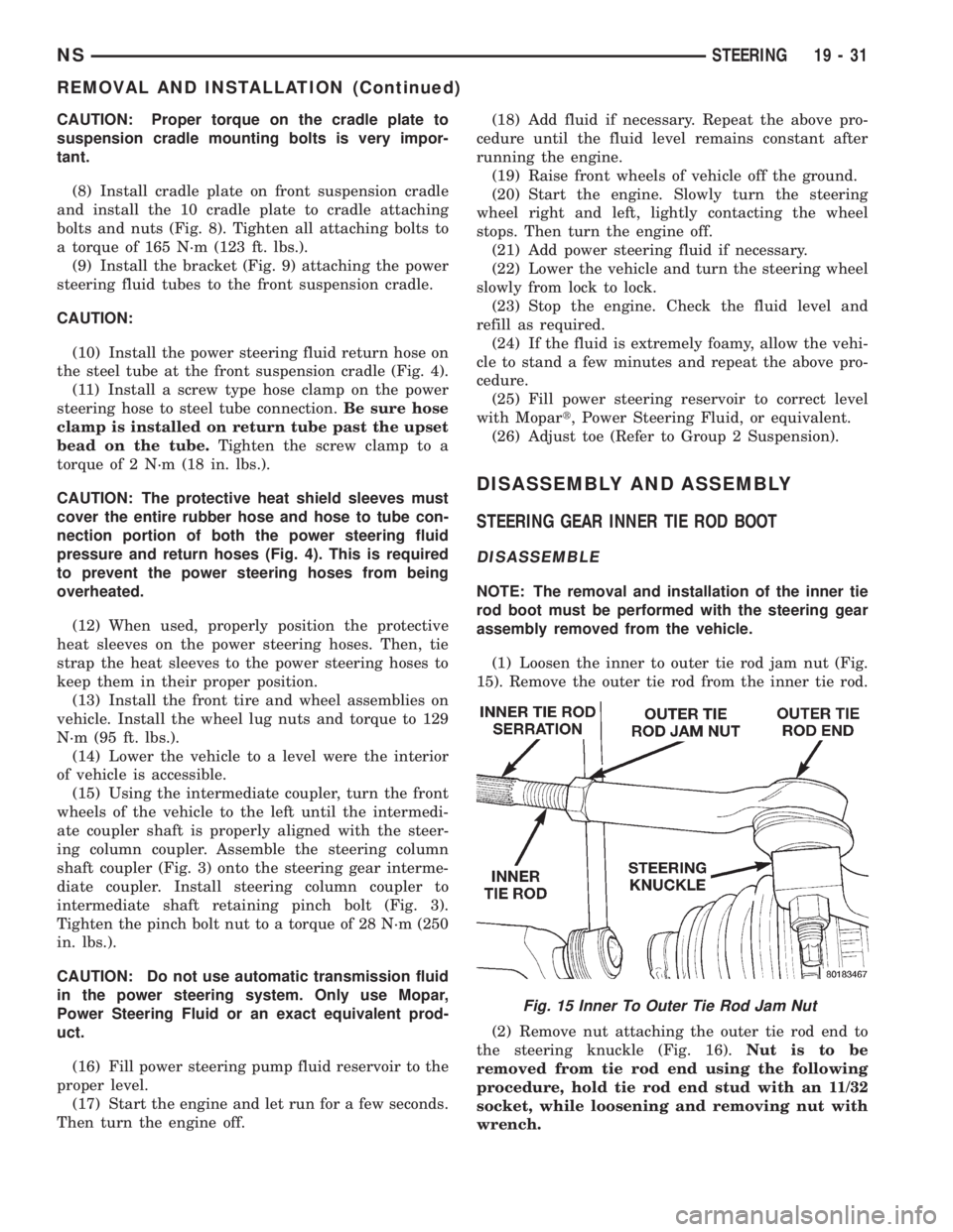
(1) Loosen the inner to outer tie rod jam nut (Fig.
15). Remove the outer tie rod from the inner tie rod.
(2) Remove nut attaching the outer tie rod end to
the steering knuckle (Fig. 16).Nut is to be
removed from tie rod end using the following
procedure, hold tie rod end stud with an 11/32
socket, while loosening and removing nut with
wrench.
Fig. 15 Inner To Outer Tie Rod Jam Nut
NSSTEERING 19 - 31
REMOVAL AND INSTALLATION (Continued)
Page 1460 of 1938
ASSEMBLE
(1) Install outer tie rod onto inner tie rod.Make
sure jam nut (Fig. 22) is on inner tie rod.
(2) Do not tighten jam nut.
(3) Install tie rod end into the steering knuckle.
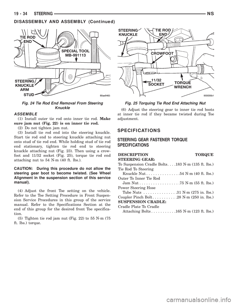
Start tie rod end to steering knuckle attaching nut
onto stud of tie rod end. While holding stud of tie rod
end stationary, tighten tie rod end to steering
knuckle attaching nut (Fig. 23). Then using a crow-
foot and 11/32 socket (Fig. 25), torque tie rod end
attaching nut to 54 N´m (40 ft. lbs.).
CAUTION: During this procedure do not allow the
steering gear boot to become twisted. (See Wheel
Alignment in the suspension section of this service
manual).
(4) Adjust the front Toe setting on the vehicle.
Refer to the Toe Setting Procedure in Front Suspen-
sion Service Procedures in this group of the service
manual. Refer to the Specifications Section at the
end of this group for the desired front Toe specifica-
tion.
(5) Tighten tie rod jam nut (Fig. 22) to 55 N´m (75
ft. lbs.) torque.(6) Adjust the steering gear to inner tie rod boots
at inner tie rod if they became twisted during Toe
adjustment.
SPECIFICATIONS
STEERING GEAR FASTENER TORQUE
SPECIFICATIONS
DESCRIPTION TORQUE
STEERING GEAR:
To Suspension Cradle Bolts. . . .183 N´m (135 ft. lbs.)
Tie Rod To Steering
Knuckle Nut...............54N´m(40ft.lbs.)
Outer To Inner Tie Rod
JamNut..................75N´m(55ft.lbs.)
Power Steering Hose
Tube Nuts...............31N´m(275 in. lbs.)
Coupler Pinch Bolt...........28N´m(250 in. lbs.)
SUSPENSION CRADLE:
Cradle Plate To Cradle
Attaching Bolts...........165 N´m (123 ft. lbs.)
Fig. 24 Tie Rod End Removal From Steering
KnuckleFig. 25 Torquing Tie Rod End Attaching Nut
19 - 34 STEERINGNS
DISASSEMBLY AND ASSEMBLY (Continued)
Page 1471 of 1938
(23) Install the 3 bolts (1 in each spoke of the
steering wheel) attaching the air bag module to the
steering wheel. Tighten the 3 air bag module attach-
ing nuts to a torque of 11 N´m (100 in. lbs.).
(24) Install the steering column cover liner (Fig. 4)
on the lower instrument panel. Install and securely
tighten the 10 bolts (Fig. 4) attaching the steering
column cover liner to the instrument panel.
(25) Install the park brake pedal release cable on
the park brake release lever in the lower steering col-
umn cover (Fig. 3).
(26) Install the lower steering column trim panel
on the lower instrument panel. Install and securely
the screws attaching the lower steering column cover
to the instrument panel (Fig. 2).
(27) Connect negative (ground) cable on the bat-
tery terminal.SPECIFICATIONS
STEERING COLUMN FASTENER TORQUE
SPECIFICATIONS
DESCRIPTION TORQUE
STEERING WHEEL:
Retaining Nut...............61N´m(45ft.lbs.)
STEERING COLUMN ASSEMBLY:
Mounting Bracket
Attaching Nuts............12N´m(105 in. lbs.)
Flex Coupler Pinch Bolt.......27N´m(240 in. lbs.)
Airbag Module Attaching Nuts . .11 N´m (100 in. lbs.)
NSSTEERING 19 - 45
REMOVAL AND INSTALLATION (Continued)
Page 1494 of 1938
(5) Continuity should exist only with transaxle in
Reverse position.
(6) No continuity should exist from either pin to
the case.
TRANSAXLE AND TORQUE CONVERTER REMOVAL
NOTE: Transaxle removal does NOT require engine
removal.
The transaxle and torque converter must be
removed as an assembly; otherwise, the torque con-
verter drive plate, pump bushing, or oil seal may be
damaged. The drive plate will not support a load;
therefore, none of the weight of the transaxle should
be allowed to rest on the plate during removal.
REMOVAL
(1) Disconnect negative battery cable.
(2) Remove air cleaner and hoses.
(3) Disconnect throttle linkage and shift linkage
from transaxle.
(4) Unplug torque converter clutch connector,
located near the dipstick. Unplug the gear position
switch.
(5) Remove transaxle dipstick tube.
(6) Remove the transaxle cooler lines and plug.
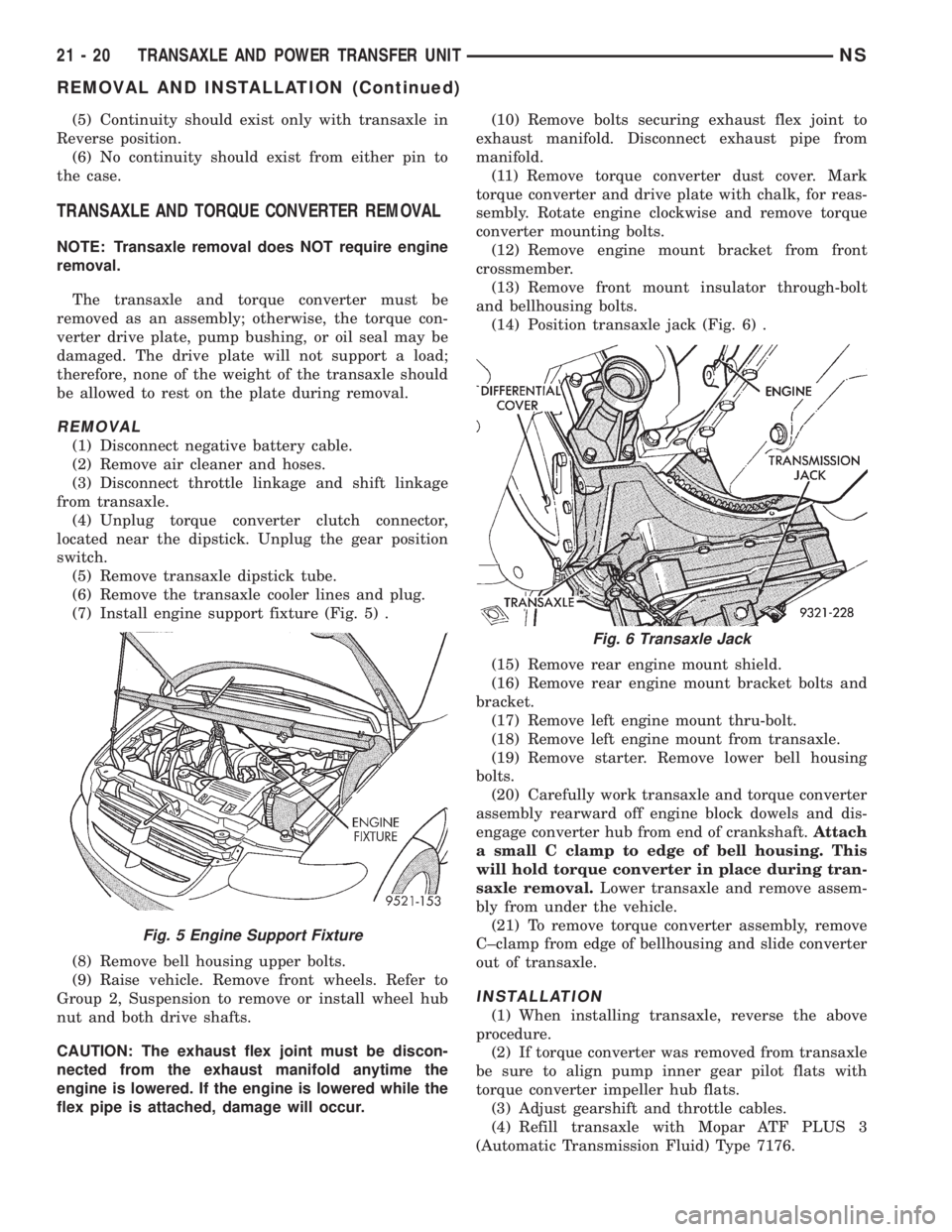
(7) Install engine support fixture (Fig. 5) .
(8) Remove bell housing upper bolts.
(9) Raise vehicle. Remove front wheels. Refer to
Group 2, Suspension to remove or install wheel hub
nut and both drive shafts.
CAUTION: The exhaust flex joint must be discon-
nected from the exhaust manifold anytime the
engine is lowered. If the engine is lowered while the
flex pipe is attached, damage will occur.(10) Remove bolts securing exhaust flex joint to
exhaust manifold. Disconnect exhaust pipe from
manifold.
(11) Remove torque converter dust cover. Mark
torque converter and drive plate with chalk, for reas-
sembly. Rotate engine clockwise and remove torque
converter mounting bolts.
(12) Remove engine mount bracket from front
crossmember.
(13) Remove front mount insulator through-bolt
and bellhousing bolts.
(14) Position transaxle jack (Fig. 6) .
(15) Remove rear engine mount shield.
(16) Remove rear engine mount bracket bolts and
bracket.
(17) Remove left engine mount thru-bolt.
(18) Remove left engine mount from transaxle.
(19) Remove starter. Remove lower bell housing
bolts.
(20) Carefully work transaxle and torque converter
assembly rearward off engine block dowels and dis-
engage converter hub from end of crankshaft.Attach
a small C clamp to edge of bell housing. This
will hold torque converter in place during tran-
saxle removal.Lower transaxle and remove assem-
bly from under the vehicle.
(21) To remove torque converter assembly, remove
C±clamp from edge of bellhousing and slide converter
out of transaxle.
INSTALLATION
(1) When installing transaxle, reverse the above
procedure.
(2) If torque converter was removed from transaxle
be sure to align pump inner gear pilot flats with
torque converter impeller hub flats.
(3) Adjust gearshift and throttle cables.
(4) Refill transaxle with Mopar ATF PLUS 3
(Automatic Transmission Fluid) Type 7176.
Fig. 5 Engine Support Fixture
Fig. 6 Transaxle Jack
21 - 20 TRANSAXLE AND POWER TRANSFER UNITNS
REMOVAL AND INSTALLATION (Continued)
Page 1564 of 1938
(8) Disconnect electrical connector at transmission
range sensor.
(9) Remove upper bellhousing upper bolts.
(10) Remove heater tube mounting bolt.(11) Remove vehicle speed sensor wiring at sensor.
(12) Remove one rear engine mount bolt from top.
(13) Remove rear engine mount shield screw.
(14) Install engine support fixture and support
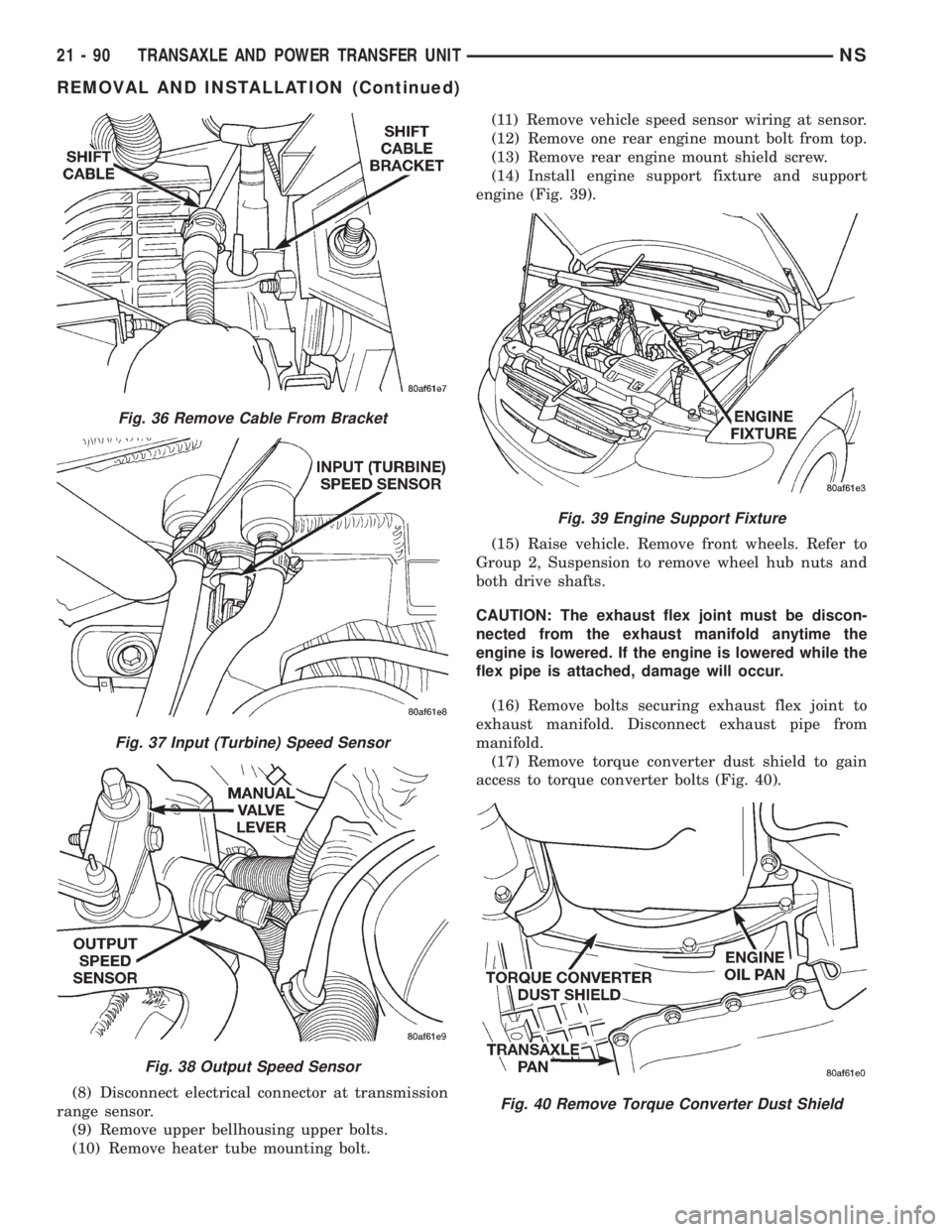
engine (Fig. 39).
(15) Raise vehicle. Remove front wheels. Refer to
Group 2, Suspension to remove wheel hub nuts and
both drive shafts.
CAUTION: The exhaust flex joint must be discon-
nected from the exhaust manifold anytime the
engine is lowered. If the engine is lowered while the
flex pipe is attached, damage will occur.
(16) Remove bolts securing exhaust flex joint to
exhaust manifold. Disconnect exhaust pipe from
manifold.
(17) Remove torque converter dust shield to gain
access to torque converter bolts (Fig. 40).
Fig. 36 Remove Cable From Bracket
Fig. 37 Input (Turbine) Speed Sensor
Fig. 38 Output Speed Sensor
Fig. 39 Engine Support Fixture
Fig. 40 Remove Torque Converter Dust Shield
21 - 90 TRANSAXLE AND POWER TRANSFER UNITNS
REMOVAL AND INSTALLATION (Continued)
Page 1775 of 1938
(18) Pass front seat belt and turning loop through
slot in quarter trim panel on three door vehicle.
(19) Pass first rear seat belt through slot in quar-
ter trim panel.
(20) Pass second rear seat belt, if equipped,
through slot in quarter trim panel on long wheel
base vehicle.
(21) Remove quarter trim panel from vehicle.
INSTALLATION
(1) Position quarter trim panel on vehicle.
(2) Pass second rear seat belt, if equipped, through
slot in quarter trim panel on long wheel base vehicle.
(3) Pass first rear seat belt through slot in quarter
trim panel.
(4) Pass front seat belt through slot in quarter
trim panel on three door vehicle.
(5) Connect wire connector into accessory power
outlet, if equipped.
(6) Align locating pins on backside of trim panel to
mating holes in inner panels.
(7) Position quarter trim panel on inner quarter
panel.
(8) Install screws to hold top of trim panel to inner
sheet metal between B-pillar and C-pillar on three
door vehicle.(9) Install screws to hold rear edge of quarter trim
to attaching bracket or inner quarter panel.
(10) Install screws to hold quarter trim to inner
quarter panel in bolster area.
(11) Install screws to hold quarter trim to inner
quarter panel in B-pillar area on three door vehicle.
(12) Install left front seat belt opening bezel into
quarter trim on three door vehicle.
(13) Install second rear seat belts anchor on long
wheel base vehicle. Tighten all seat belt bolts to 39
N´m (28 in. lbs.) torque.
(14) Install first rear seat belt anchor.
(15) Install left D-pillar trim panel.
(16) Install C-pillar trim panel.
(17) Install upper left B-pillar trim on three door
vehicle.
(18) Install left quarter trim bolster.
(19) Install front door sill plate on three door vehi-
cle.
(20) Install sliding door sill plate on four door
vehicle.
(21) Install second rear seat, if equipped.
(22) Install first rear seat.
(23) Connect the battery negative cable.
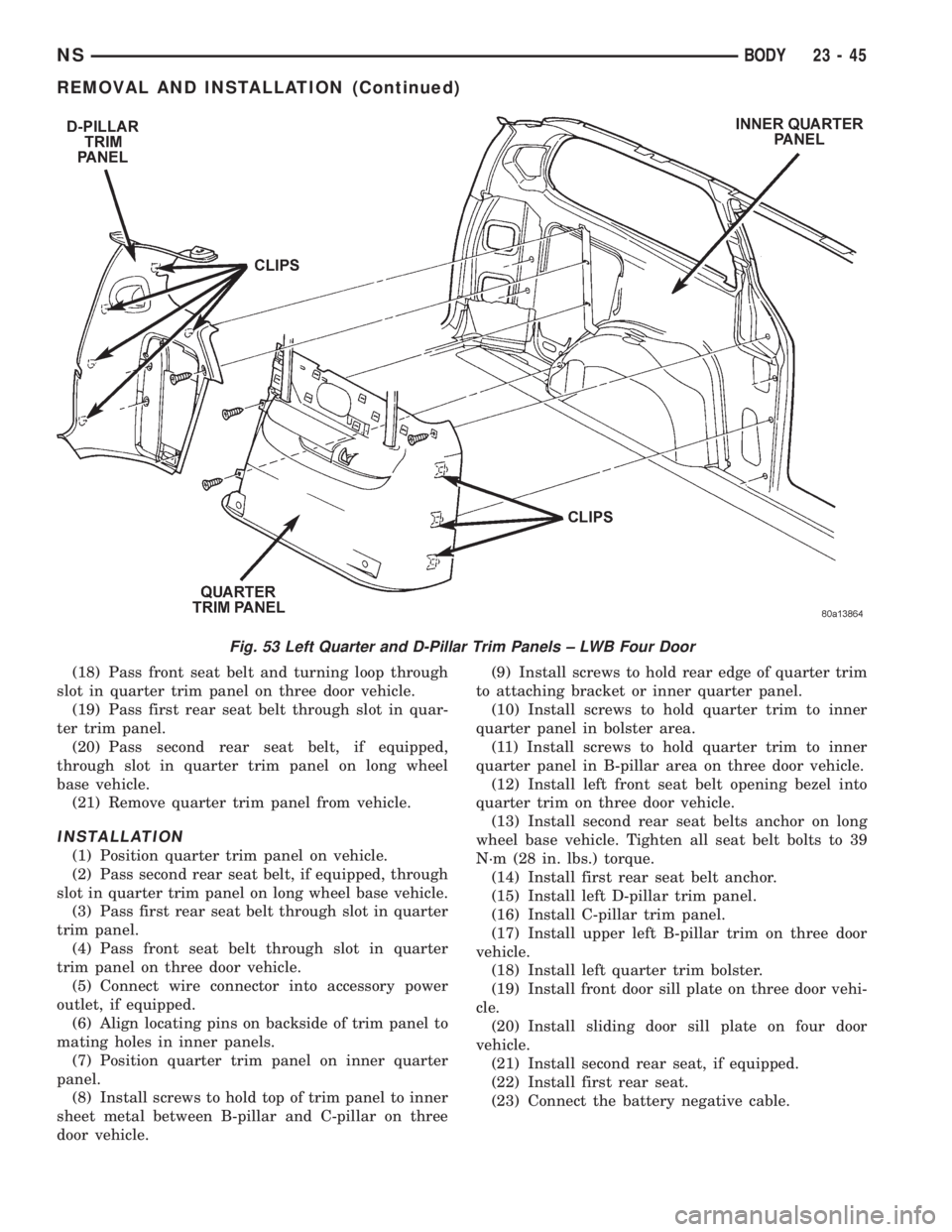
Fig. 53 Left Quarter and D-Pillar Trim Panels ± LWB Four Door
NSBODY 23 - 45
REMOVAL AND INSTALLATION (Continued)