1996 CHRYSLER VOYAGER wheel bolt torque
[x] Cancel search: wheel bolt torquePage 1162 of 1938
(3) Rotate crankshaft so that the oil pump drive
flats are vertical.
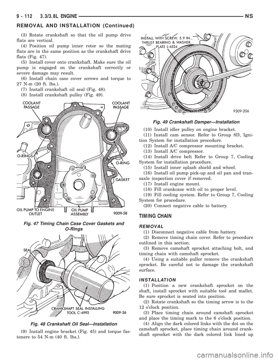
(4) Position oil pump inner rotor so the mating
flats are in the same position as the crankshaft drive
flats (Fig. 47).
(5) Install cover onto crankshaft. Make sure the oil
pump is engaged on the crankshaft correctly or
severe damage may result.
(6) Install chain case cover screws and torque to
27 N´m (20 ft. lbs.).
(7) Install crankshaft oil seal (Fig. 48).
(8) Install crankshaft pulley (Fig. 49).
(9) Install engine bracket (Fig. 45) and torque fas-
teners to 54 N´m (40 ft. lbs.).(10) Install idler pulley on engine bracket.
(11) Install cam sensor. Refer to Group 8D, Igni-
tion System for installation procedure.
(12) Install A/C compressor mounting bracket.
(13) Install A/C compressor.
(14) Install drive belt Refer to Group 7, Cooling
System for installation procedure.
(15) Install inner splash shield and wheel.
(16) Install oil pump pick-up and oil pan and tran-
saxle inspection cover if removed.
(17) Install engine mount.
(18) Fill crankcase with oil to proper level.
(19) Fill cooling system. Refer to Group 7, Cooling
System for procedure.
(20) Connect negative cable to battery.
TIMING CHAIN
REMOVAL
(1) Disconnect negative cable from battery.
(2) Remove timing chain cover. Refer to procedure
outlined in this section.
(3) Remove camshaft sprocket attaching bolt, and
timing chain with camshaft sprocket.
(4) Using a suitable puller remove the crankshaft
sprocket. Be careful not to damage the crankshaft
surface.
INSTALLATION
(1) Position a new crankshaft sprocket on the
shaft, install sprocket with suitable tool and mallet.
Be sure sprocket is seated into position.
(2) Rotate crankshaft so the timing arrow is to the
12 o'clock position.
(3) Place timing chain around camshaft sprocket
and place the timing mark to the 6 o'clock position.
(4) Align the dark colored links with the dot on the
camshaft sprocket, place timing chain around crank-
shaft sprocket with the dark colored link lined up
Fig. 47 Timing Chain Case Cover Gaskets and
O-Rings
Fig. 48 Crankshaft Oil SealÐInstallation
Fig. 49 Crankshaft DamperÐInstallation
9 - 112 3.3/3.8L ENGINENS
REMOVAL AND INSTALLATION (Continued)
Page 1229 of 1938
(6) Refer to crankshaft main bearing Installation if
not in specification.
NOTE: If engine is disassembled refer to Crank-
shaft Main Bearing Removal and Installation for this
procedure.
REMOVAL AND INSTALLATION
ENGINE MOUNTÐFRONT
(1) Disconnect battery.
(2) Remove lower air dam at front fascia.
(3) Remove the bolts holding tow bracket and front
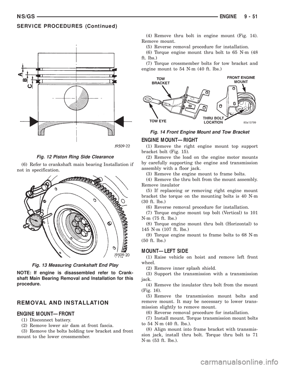
mount to the lower crossmember.(4) Remove thru bolt in engine mount (Fig. 14).
Remove mount.
(5) Reverse removal procedure for installation.
(6) Torque engine mount thru bolt to 65 N´m (48
ft. lbs.)
(7) Torque crossmember bolts for tow bracket and
engine mount to 54 N´m (40 ft. lbs.)
ENGINE MOUNTÐRIGHT
(1) Remove the right engine mount top support
bracket bolt (Fig. 15).
(2) Remove the load on the engine motor mounts
by carefully supporting the engine and transmission
assembly with a floor jack.
(3) Remove the engine mount to frame bolts.
(4) Remove the thru bolt from the mount assembly.
Remove insulator
(5) If replaceing or removing right engine mount
bracket the torque on the mounting bolts is 40 N´m
(30 ft. lbs.)
(6) Reverse removal procedure for installation.
(7) Torque engine mount top bolt (Vertical) to 101
N´m (75 ft. lbs.)
(8) Torque engine mount thru bolt (Horizontal) to
145 N´m (107 ft. lbs.)
(9) Torque engine mount to frame bolts to 68 N´m
(50 ft. lbs.)
MOUNTÐLEFT SIDE
(1) Raise vehicle on hoist and remove left front
wheel.
(2) Remove inner splash shield.
(3) Support the transmission with a transmission
jack.
(4) Remove the insulator thru bolt from the mount
(Fig. 16).
(5) Remove the transmission mount bolts and
remove mount. It may be necessary to lower trans-
mission slightly to remove mount.
(6) Reverse removal procedure for installation.
(7) Install mount. Torque transmission mount bolts
to 54 N´m (40 ft. lbs.).
(8) Align mount into frame bracket with transmis-
sion jack, install thru bolt. Torque thru bolt to 71
N´m (53 ft. lbs.).
Fig. 12 Piston Ring Side Clearance
Fig. 13 Measuring Crankshaft End Play
Fig. 14 Front Engine Mount and Tow Bracket
NS/GSENGINE 9 - 51
SERVICE PROCEDURES (Continued)
Page 1242 of 1938
(13) Remove pistons and connecting rods from
block.
(14) Remove vibration damper. Refer to procedure
in this section.
(15) Remove front cover. Refer to procedure in this
section.
(16) Remove oil pump drive gear.
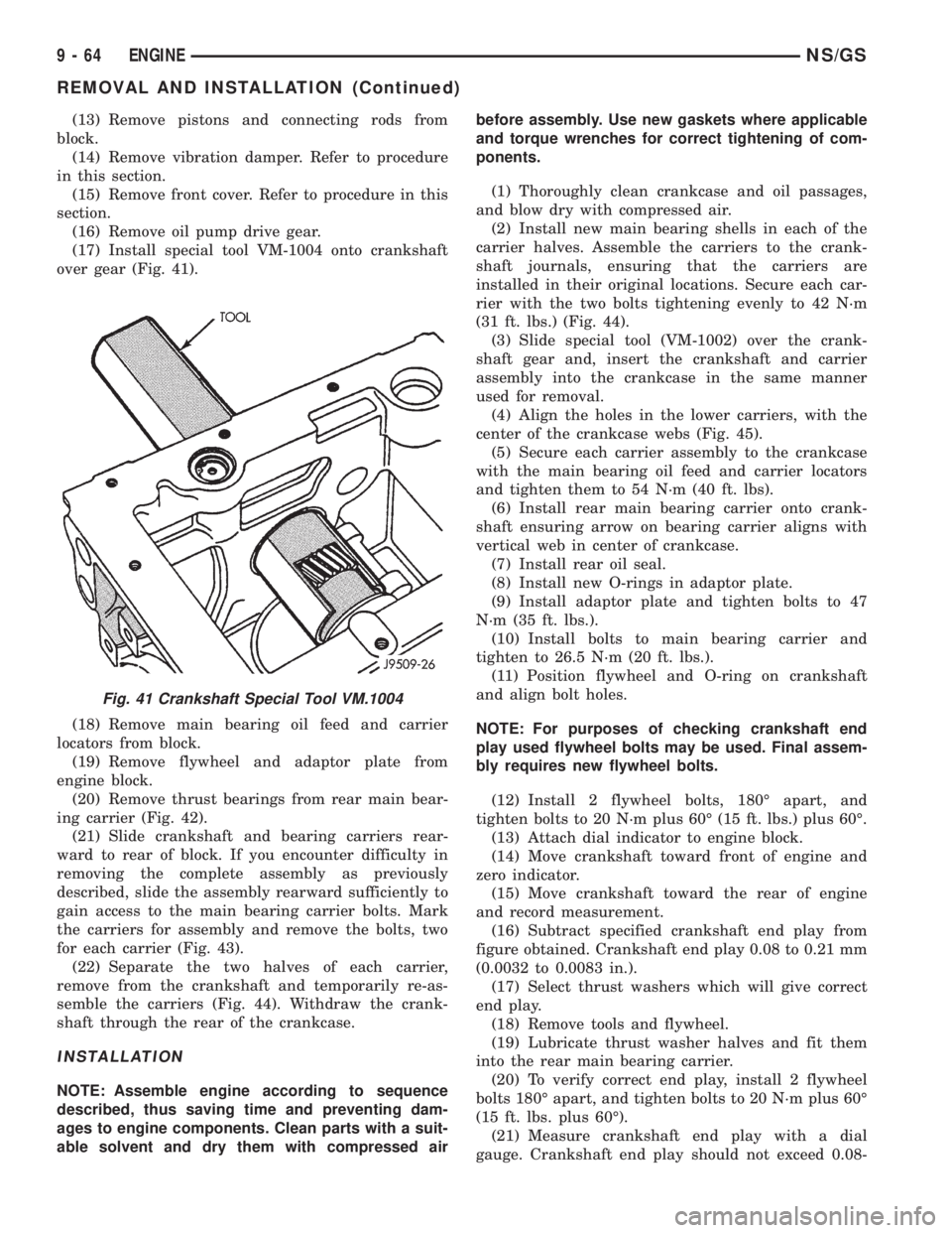
(17) Install special tool VM-1004 onto crankshaft
over gear (Fig. 41).
(18) Remove main bearing oil feed and carrier
locators from block.
(19) Remove flywheel and adaptor plate from
engine block.
(20) Remove thrust bearings from rear main bear-
ing carrier (Fig. 42).
(21) Slide crankshaft and bearing carriers rear-
ward to rear of block. If you encounter difficulty in
removing the complete assembly as previously
described, slide the assembly rearward sufficiently to
gain access to the main bearing carrier bolts. Mark
the carriers for assembly and remove the bolts, two
for each carrier (Fig. 43).
(22) Separate the two halves of each carrier,
remove from the crankshaft and temporarily re-as-
semble the carriers (Fig. 44). Withdraw the crank-
shaft through the rear of the crankcase.
INSTALLATION
NOTE: Assemble engine according to sequence
described, thus saving time and preventing dam-
ages to engine components. Clean parts with a suit-
able solvent and dry them with compressed airbefore assembly. Use new gaskets where applicable
and torque wrenches for correct tightening of com-
ponents.
(1) Thoroughly clean crankcase and oil passages,
and blow dry with compressed air.
(2) Install new main bearing shells in each of the
carrier halves. Assemble the carriers to the crank-
shaft journals, ensuring that the carriers are
installed in their original locations. Secure each car-
rier with the two bolts tightening evenly to 42 N´m
(31 ft. lbs.) (Fig. 44).
(3) Slide special tool (VM-1002) over the crank-
shaft gear and, insert the crankshaft and carrier
assembly into the crankcase in the same manner
used for removal.
(4) Align the holes in the lower carriers, with the
center of the crankcase webs (Fig. 45).
(5) Secure each carrier assembly to the crankcase
with the main bearing oil feed and carrier locators
and tighten them to 54 N´m (40 ft. lbs).
(6) Install rear main bearing carrier onto crank-
shaft ensuring arrow on bearing carrier aligns with
vertical web in center of crankcase.
(7) Install rear oil seal.
(8) Install new O-rings in adaptor plate.
(9) Install adaptor plate and tighten bolts to 47
N´m (35 ft. lbs.).
(10) Install bolts to main bearing carrier and
tighten to 26.5 N´m (20 ft. lbs.).
(11) Position flywheel and O-ring on crankshaft
and align bolt holes.
NOTE: For purposes of checking crankshaft end
play used flywheel bolts may be used. Final assem-
bly requires new flywheel bolts.
(12) Install 2 flywheel bolts, 180É apart, and
tighten bolts to 20 N´m plus 60É (15 ft. lbs.) plus 60É.
(13) Attach dial indicator to engine block.
(14) Move crankshaft toward front of engine and
zero indicator.
(15) Move crankshaft toward the rear of engine
and record measurement.
(16) Subtract specified crankshaft end play from
figure obtained. Crankshaft end play 0.08 to 0.21 mm
(0.0032 to 0.0083 in.).
(17) Select thrust washers which will give correct
end play.
(18) Remove tools and flywheel.
(19) Lubricate thrust washer halves and fit them
into the rear main bearing carrier.
(20) To verify correct end play, install 2 flywheel
bolts 180É apart, and tighten bolts to 20 N´m plus 60É
(15 ft. lbs. plus 60É).
(21) Measure crankshaft end play with a dial
gauge. Crankshaft end play should not exceed 0.08-
Fig. 41 Crankshaft Special Tool VM.1004
9 - 64 ENGINENS/GS
REMOVAL AND INSTALLATION (Continued)
Page 1243 of 1938
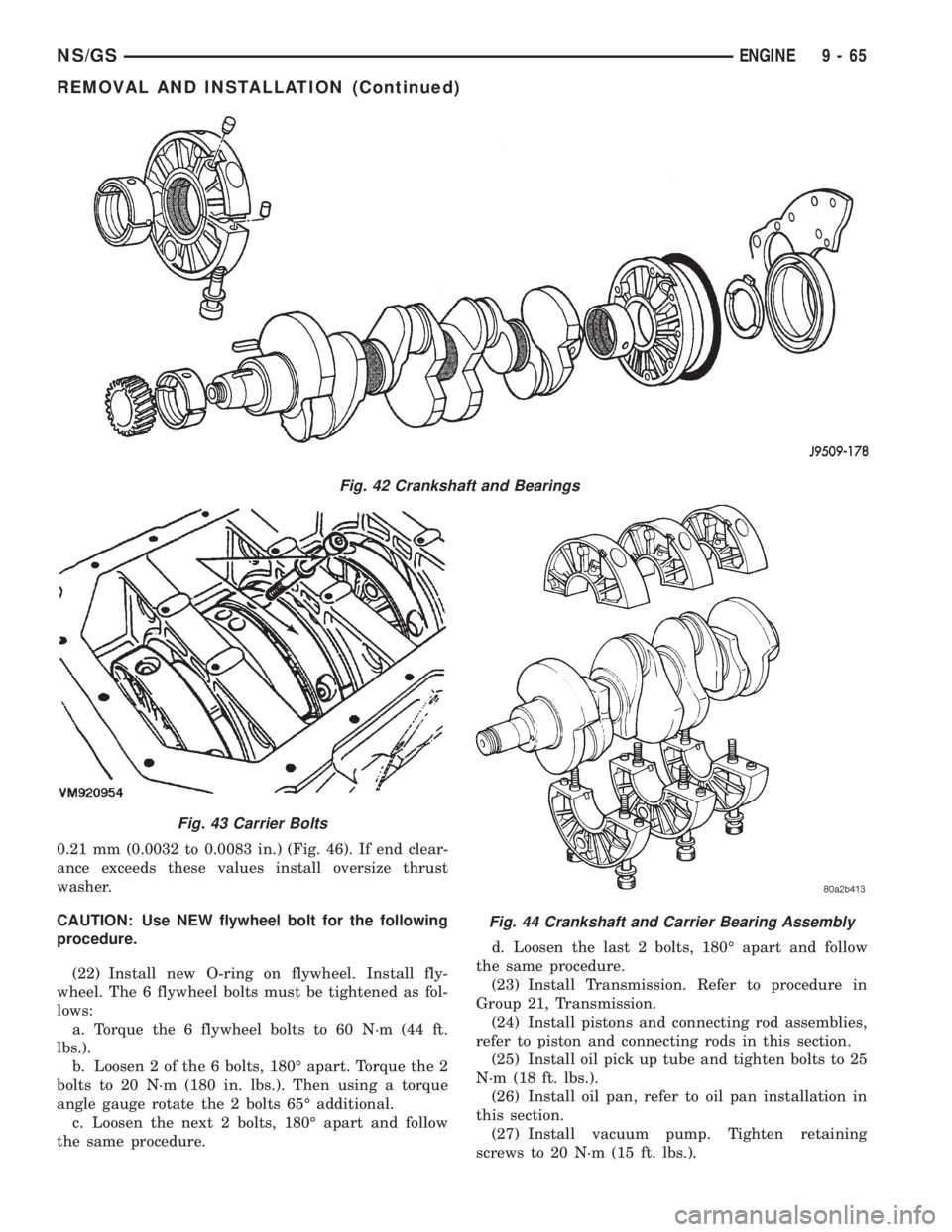
0.21 mm (0.0032 to 0.0083 in.) (Fig. 46). If end clear-
ance exceeds these values install oversize thrust
washer.
CAUTION: Use NEW flywheel bolt for the following
procedure.
(22) Install new O-ring on flywheel. Install fly-
wheel. The 6 flywheel bolts must be tightened as fol-
lows:
a. Torque the 6 flywheel bolts to 60 N´m (44 ft.
lbs.).
b. Loosen 2 of the 6 bolts, 180É apart. Torque the 2
bolts to 20 N´m (180 in. lbs.). Then using a torque
angle gauge rotate the 2 bolts 65É additional.
c. Loosen the next 2 bolts, 180É apart and follow
the same procedure.d. Loosen the last 2 bolts, 180É apart and follow
the same procedure.
(23) Install Transmission. Refer to procedure in
Group 21, Transmission.
(24) Install pistons and connecting rod assemblies,
refer to piston and connecting rods in this section.
(25) Install oil pick up tube and tighten bolts to 25
N´m (18 ft. lbs.).
(26) Install oil pan, refer to oil pan installation in
this section.
(27) Install vacuum pump. Tighten retaining
screws to 20 N´m (15 ft. lbs.).
Fig. 42 Crankshaft and Bearings
Fig. 43 Carrier Bolts
Fig. 44 Crankshaft and Carrier Bearing Assembly
NS/GSENGINE 9 - 65
REMOVAL AND INSTALLATION (Continued)
Page 1251 of 1938
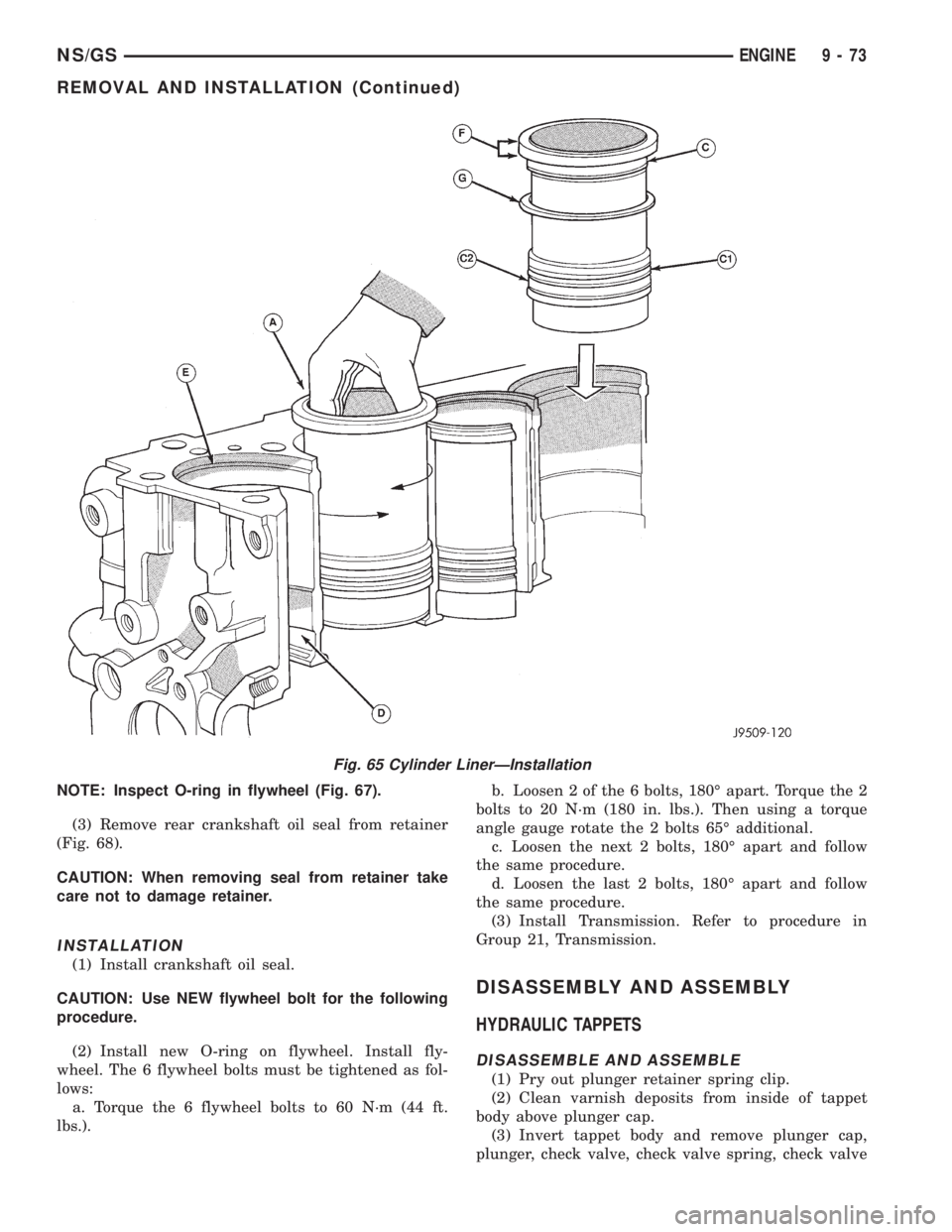
NOTE: Inspect O-ring in flywheel (Fig. 67).
(3) Remove rear crankshaft oil seal from retainer
(Fig. 68).
CAUTION: When removing seal from retainer take
care not to damage retainer.
INSTALLATION
(1) Install crankshaft oil seal.
CAUTION: Use NEW flywheel bolt for the following
procedure.
(2) Install new O-ring on flywheel. Install fly-
wheel. The 6 flywheel bolts must be tightened as fol-
lows:
a. Torque the 6 flywheel bolts to 60 N´m (44 ft.
lbs.).b. Loosen 2 of the 6 bolts, 180É apart. Torque the 2
bolts to 20 N´m (180 in. lbs.). Then using a torque
angle gauge rotate the 2 bolts 65É additional.
c. Loosen the next 2 bolts, 180É apart and follow
the same procedure.
d. Loosen the last 2 bolts, 180É apart and follow
the same procedure.
(3) Install Transmission. Refer to procedure in
Group 21, Transmission.
DISASSEMBLY AND ASSEMBLY
HYDRAULIC TAPPETS
DISASSEMBLE AND ASSEMBLE
(1) Pry out plunger retainer spring clip.
(2) Clean varnish deposits from inside of tappet
body above plunger cap.
(3) Invert tappet body and remove plunger cap,
plunger, check valve, check valve spring, check valve
Fig. 65 Cylinder LinerÐInstallation
NS/GSENGINE 9 - 73
REMOVAL AND INSTALLATION (Continued)
Page 1258 of 1938
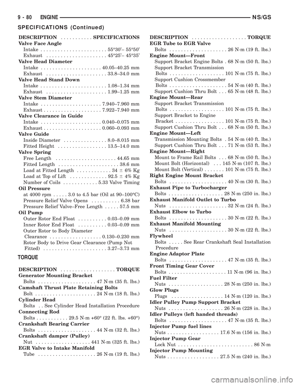
DESCRIPTION...........SPECIFICATIONS
Valve Face Angle
Intake.......................55É30'± 55É50'
Exhaust.....................45É25'± 45É35'
Valve Head Diameter
Intake.....................40.05±40.25 mm
Exhaust.....................33.8±34.0 mm
Valve Head Stand Down
Intake.......................1.08±1.34 mm
Exhaust.....................1.99±1.25 mm
Valve Stem Diameter
Intake.....................7.940±7.960 mm
Exhaust....................7.922±7.940 mm
Valve Clearance in Guide
Intake.....................0.040±0.075 mm
Exhaust....................0.060±0.093 mm
Valve Guide
Inside Diameter...............8.0±8.015 mm
Fitted Height.................13.5±14.0 mm
Valve Spring
Free Length.....................44.65 mm
Fitted Length.....................38.6 mm
Load at Fitted Length............3466% Kg
Load at Top of Lift.............92.564% Kg
Number of Coils............5.33 Valve Timing
Oil Pressure
at 4000 rpm.....3.0to4.5bar(Oil at 90±100ÉC)
Pressure Relief Valve Opens..........6.38 bar
Pressure Relief Valve±Free Length.....57.5 mm
Oil Pump
Outer Rotor End Float..........0.03±0.09 mm
Inner Rotor End Float..........0.03±0.09 mm
Outer Rotor to Body Diameter
Clearance..................0.130±0.230 mm
Rotor Body to Drive Gear Clearance (Pump Not
Fitted)......................3.27±3.73 mm
TORQUE
DESCRIPTION...................TORQUE
Generator Mounting Bracket
Bolts....................47N´m(35ft.lbs.)
Camshaft Thrust Plate Retaining Bolts
Bolt.....................24N´m(18ft.lbs.)
Cylinder Head
Bolts . . See Cylinder Head Installation Procedure
Connecting Rod
Bolts...........29.5 N´m +60É (22 ft. lbs. +60É)
Crankshaft Bearing Carrier
Bolts....................44N´m(32ft.lbs.)
Crankshaft damper (Pulley)
Nut ...................441N´m(325 ft. lbs.)
EGR Valve to Intake Manifold
Tube ....................26N´m(19ft.lbs.)DESCRIPTION...................TORQUE
EGR Tube to EGR Valve
Bolts....................26N´m(19ft.lbs.)
Engine MountÐFront
Support Bracket Engine Bolts . 68 N´m (50 ft. lbs.)
Support Bracket Transmission
Bolts...................101N´m(75ft.lbs.)
Support Cushion Crossmember
Bolts....................54N´m(40ft.lbs.)
Support Cushion Thru Bolt . . . 65 N´m (48 ft. lbs.)
Engine MountÐRear
Support Bracket Transmission
Bolts...................101N´m(75ft.lbs.)
Support Bracket to Engine
Bracket.................101N´m(75ft.lbs.)
Support Cushion Thru Bolt . . . 68 N´m (50 ft. lbs.)
Engine MountÐLeft
Transmission Mounting Bolts . 54 N´m (40 ft. lbs.)
Support Cushion Thru Bolt . . . 71 N´m (53 ft. lbs.)
Engine MountÐRight
Mount to Frame Rail Bolts . . . 68 N´m (50 ft. lbs.)
Mount Bolt (Horizontal) . . . 145 N´m (107 ft. lbs.)
Mount Bolt (Vertical).......101N´m(75ft.lbs.)
Right Engine Mount Bracket
Bolts....................40N´m(30ft.lbs.)
Exhaust Pipe to Turbocharger
Bolts...................28N´m(250 in. lbs.)
Exhaust Manifold Outlet to Turbo
Nuts....................32N´m(24ft.lbs.)
Exhaust Elbow to Turbo
Bolts....................30N´m(22ft.lbs.)
Exhaust Manifold Mounting
Nuts....................30N´m(22ft.lbs.)
Flywheel
Bolts.....SeeRear Crankshaft Seal Installation
Procedure
Engine Adaptor Plate
Bolts....................47N´m(35ft.lbs.)
Front Timing Gear Cover
Bolts....................11N´m(96in.lbs.)
Fuel Filter
Nuts...................28N´m(250 in. lbs.)
Glow Plugs
Plugs..................14N´m(120 in. lbs.)
Idler Pulley Pump Support Bracket
Nuts...................26N´m(228 in. lbs.)
Idler Pulleys (left handed threads)
Bolts....................47N´m(35ft.lbs.)
Injector Pump fuel lines
Nuts..................17.6 N´m (156 in. lbs.)
Injector Pump Gear
Lock Nut..........................86N´m
Injector Pump Mounting
Nuts..................27.5 N´m (240 in. lbs.)
9 - 80 ENGINENS/GS
SPECIFICATIONS (Continued)
Page 1285 of 1938
(7) Connect lower ball joints to lower control arms.
Refer to Group 2, Suspension.
(8) Connect stabilizer bar links to ends of stabi-
lizer bar. Refer to Group 2, Suspension.
(9) Install bolts to hold anti-lock brake sensor
leads to crossmember.
(10) Install high pressure hose to pump.
(11) Connect return hose to metal tube.
(12) Tighten hose clamp at the crossmember cou-
pling.
(13) Remove pinch-off pliers.
(14) Position steering so front wheels are straight
ahead.
(15) Install steering column coupling to telescoping
steering gear shaft.
(16) Install clinch bolt to hold steering column cou-
pling to steering gear shaft.
(17) Install knee blocker reinforcement. Refer to
Group 8E, Instrument Panel and Systems.
(18) Install steering column lower cover from
instrument panel. Refer to Group 8E, Instrument
Panel and Systems.
(19) Connect battery negative cable.
FRONT CROSSMEMBER MOUNT BUSHINGS
REMOVAL
(1) Using paint or grease pencil, mark outline of
crossmember on frame rails.
(2) Loosen bolts holding crossmember to frame
rails.
(3) Remove bolt on bushing that requires replace-
ment.
(4) Allow crossmember to drop down enough to
gain clearance for bushing removal.
(5) Remove bushing from vehicle.
INSTALLATION
(1) Apply rubber lube or soap to replacement bush-
ing.(2) Insert lower half of bushing into square hole in
crossmember.
(3) Place upper half of bushing on top of cross-
member aligned to receive square tube protruding
upward from lower bushing half.
(4) Squeeze bushing halves together to ensure they
are properly mated.
(5) Lift crossmember upward to close gap between
the bushing and frame.
(6) Verify that lower bushing is fully seated into
crossmember and upper bushing.
(7) Install bolt to hold bushing and crossmember
to frame rail hand tight.
(8) Align crossmember to reference marks on
frame rails.
(9) Tighten crossmember to frame rails attaching
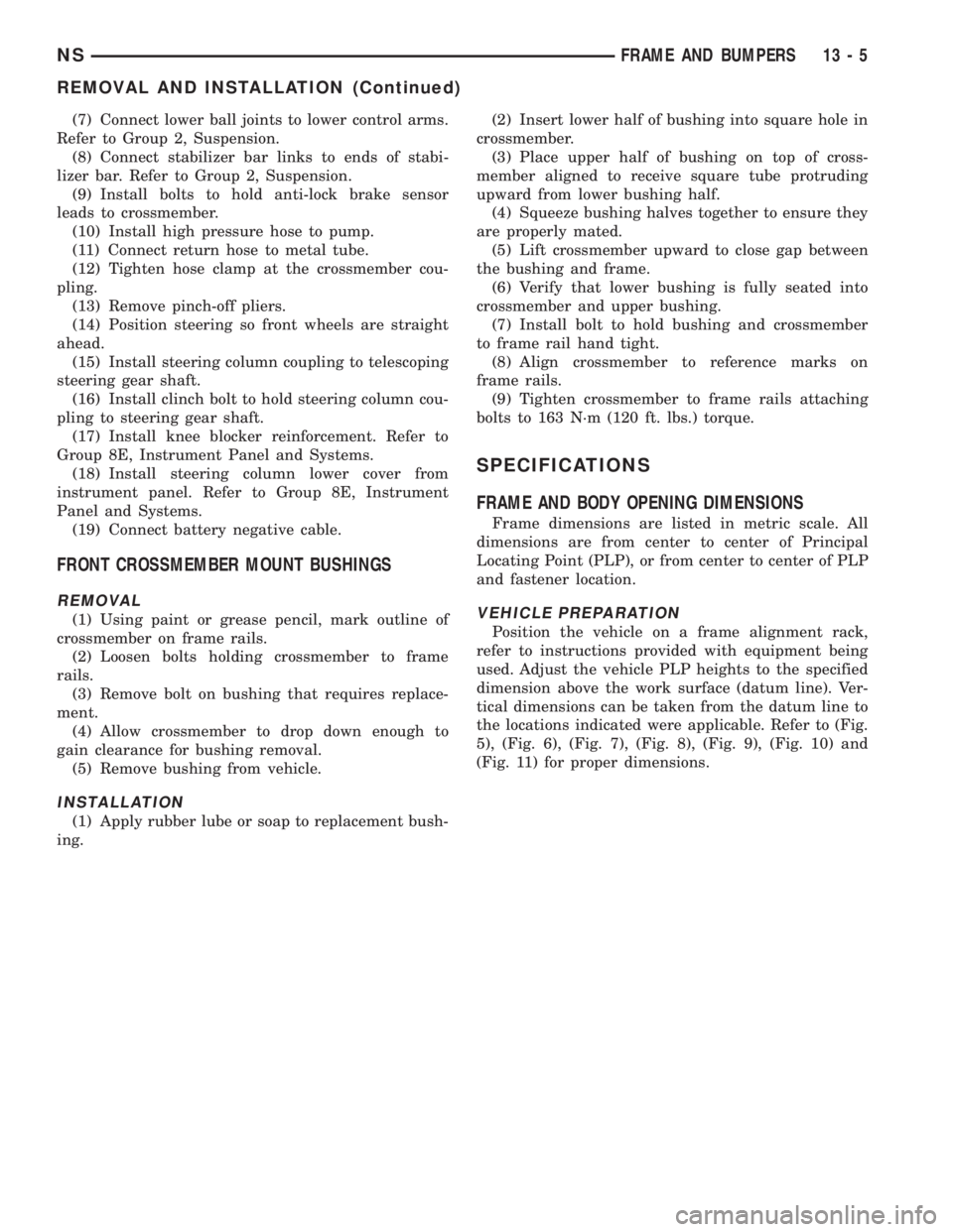
bolts to 163 N´m (120 ft. lbs.) torque.
SPECIFICATIONS
FRAME AND BODY OPENING DIMENSIONS
Frame dimensions are listed in metric scale. All
dimensions are from center to center of Principal
Locating Point (PLP), or from center to center of PLP
and fastener location.
VEHICLE PREPARATION
Position the vehicle on a frame alignment rack,
refer to instructions provided with equipment being
used. Adjust the vehicle PLP heights to the specified
dimension above the work surface (datum line). Ver-
tical dimensions can be taken from the datum line to
the locations indicated were applicable. Refer to (Fig.
5), (Fig. 6), (Fig. 7), (Fig. 8), (Fig. 9), (Fig. 10) and
(Fig. 11) for proper dimensions.
NSFRAME AND BUMPERS 13 - 5
REMOVAL AND INSTALLATION (Continued)
Page 1428 of 1938
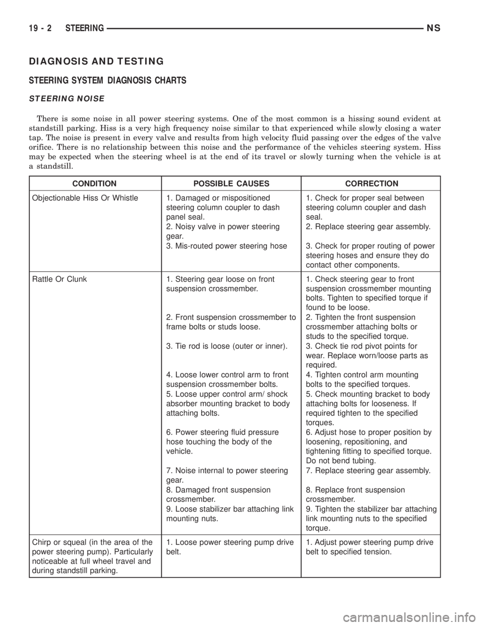
DIAGNOSIS AND TESTING
STEERING SYSTEM DIAGNOSIS CHARTS
STEERING NOISE
There is some noise in all power steering systems. One of the most common is a hissing sound evident at
standstill parking. Hiss is a very high frequency noise similar to that experienced while slowly closing a water
tap. The noise is present in every valve and results from high velocity fluid passing over the edges of the valve
orifice. There is no relationship between this noise and the performance of the vehicles steering system. Hiss
may be expected when the steering wheel is at the end of its travel or slowly turning when the vehicle is at
a standstill.
CONDITION POSSIBLE CAUSES CORRECTION
Objectionable Hiss Or Whistle 1. Damaged or mispositioned
steering column coupler to dash
panel seal.1. Check for proper seal between
steering column coupler and dash
seal.
2. Noisy valve in power steering
gear.2. Replace steering gear assembly.
3. Mis-routed power steering hose 3. Check for proper routing of power
steering hoses and ensure they do
contact other components.
Rattle Or Clunk 1. Steering gear loose on front
suspension crossmember.1. Check steering gear to front
suspension crossmember mounting
bolts. Tighten to specified torque if
found to be loose.
2. Front suspension crossmember to
frame bolts or studs loose.2. Tighten the front suspension
crossmember attaching bolts or
studs to the specified torque.
3. Tie rod is loose (outer or inner). 3. Check tie rod pivot points for
wear. Replace worn/loose parts as
required.
4. Loose lower control arm to front
suspension crossmember bolts.4. Tighten control arm mounting
bolts to the specified torques.
5. Loose upper control arm/ shock
absorber mounting bracket to body
attaching bolts.5. Check mounting bracket to body
attaching bolts for looseness. If
required tighten to the specified
torques.
6. Power steering fluid pressure
hose touching the body of the
vehicle.6. Adjust hose to proper position by
loosening, repositioning, and
tightening fitting to specified torque.
Do not bend tubing.
7. Noise internal to power steering
gear.7. Replace steering gear assembly.
8. Damaged front suspension
crossmember.8. Replace front suspension
crossmember.
9. Loose stabilizer bar attaching link
mounting nuts.9. Tighten the stabilizer bar attaching
link mounting nuts to the specified
torque.
Chirp or squeal (in the area of the
power steering pump). Particularly
noticeable at full wheel travel and
during standstill parking.1. Loose power steering pump drive
belt.1. Adjust power steering pump drive
belt to specified tension.
19 - 2 STEERINGNS