1996 CHRYSLER VOYAGER oil type
[x] Cancel search: oil typePage 1553 of 1938
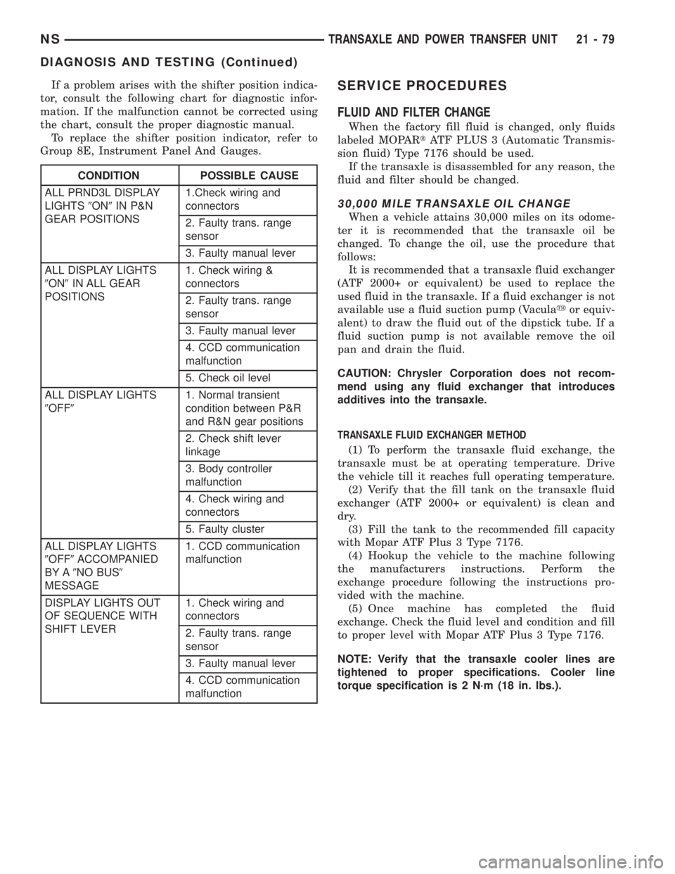
If a problem arises with the shifter position indica-
tor, consult the following chart for diagnostic infor-
mation. If the malfunction cannot be corrected using
the chart, consult the proper diagnostic manual.
To replace the shifter position indicator, refer to
Group 8E, Instrument Panel And Gauges.SERVICE PROCEDURES
FLUID AND FILTER CHANGE
When the factory fill fluid is changed, only fluids
labeled MOPARtATF PLUS 3 (Automatic Transmis-
sion fluid) Type 7176 should be used.
If the transaxle is disassembled for any reason, the
fluid and filter should be changed.
30,000 MILE TRANSAXLE OIL CHANGE
When a vehicle attains 30,000 miles on its odome-
ter it is recommended that the transaxle oil be
changed. To change the oil, use the procedure that
follows:
It is recommended that a transaxle fluid exchanger
(ATF 2000+ or equivalent) be used to replace the
used fluid in the transaxle. If a fluid exchanger is not
available use a fluid suction pump (Vaculayor equiv-
alent) to draw the fluid out of the dipstick tube. If a
fluid suction pump is not available remove the oil
pan and drain the fluid.
CAUTION: Chrysler Corporation does not recom-
mend using any fluid exchanger that introduces
additives into the transaxle.
TRANSAXLE FLUID EXCHANGER METHOD
(1) To perform the transaxle fluid exchange, the
transaxle must be at operating temperature. Drive
the vehicle till it reaches full operating temperature.
(2) Verify that the fill tank on the transaxle fluid
exchanger (ATF 2000+ or equivalent) is clean and
dry.
(3) Fill the tank to the recommended fill capacity
with Mopar ATF Plus 3 Type 7176.
(4) Hookup the vehicle to the machine following
the manufacturers instructions. Perform the
exchange procedure following the instructions pro-
vided with the machine.
(5) Once machine has completed the fluid
exchange. Check the fluid level and condition and fill
to proper level with Mopar ATF Plus 3 Type 7176.
NOTE: Verify that the transaxle cooler lines are
tightened to proper specifications. Cooler line
torque specification is 2 N´m (18 in. lbs.).
CONDITION POSSIBLE CAUSE
ALL PRND3L DISPLAY
LIGHTS9ON9IN P&N
GEAR POSITIONS1.Check wiring and
connectors
2. Faulty trans. range
sensor
3. Faulty manual lever
ALL DISPLAY LIGHTS
9ON9IN ALL GEAR
POSITIONS1. Check wiring &
connectors
2. Faulty trans. range
sensor
3. Faulty manual lever
4. CCD communication
malfunction
5. Check oil level
ALL DISPLAY LIGHTS
9OFF91. Normal transient
condition between P&R
and R&N gear positions
2. Check shift lever
linkage
3. Body controller
malfunction
4. Check wiring and
connectors
5. Faulty cluster
ALL DISPLAY LIGHTS
9OFF9ACCOMPANIED
BY A9NO BUS9
MESSAGE1. CCD communication
malfunction
DISPLAY LIGHTS OUT
OF SEQUENCE WITH
SHIFT LEVER1. Check wiring and
connectors
2. Faulty trans. range
sensor
3. Faulty manual lever
4. CCD communication
malfunction
NSTRANSAXLE AND POWER TRANSFER UNIT 21 - 79
DIAGNOSIS AND TESTING (Continued)
Page 1554 of 1938
DIPSTICK TUBE FLUID SUCTION METHOD
(1) When performing the fluid suction method,
make sure the transaxle is at full operating temper-
ature.
(2) To perform the dipstick tube fluid suction
method, use a suitable fluid suction device (Vaculay
or equivalent).
(3) Insert the fluid suction line into the dipstick
tube.
NOTE: Verify that the suction line is inserted to the
lowest point of the transaxle oil pan. This will
ensure complete evacuation of the fluid in the pan.
(4) Follow the manufacturers recommended proce-
dure and evacuate the fluid from the transaxle.
(5) Remove the suction line from the dipstick tube.
(6) Add 4 Quarts of Mopar ATF Plus 3 Type 7176
transaxle fluid.
(7) Start the engine and allow it to idle for a min-
imum of one minute. With the parking brake applied,
press your foot on the service brake and cycle the
transaxle from park to all gear positions ending in
neutral or park.
(8) Check the transaxle fluid level and add an
appropriate amount to bring the transaxle fluid level
to 3mm (1/8 in.) below the ADD mark on the dip-
stick.
(9) Recheck the fluid level after the transaxle is at
normal operating temperature. The level should be in
the HOT range.
TRANSAXLE OIL PAN DROP METHOD
This procedure involves removing the transaxle oil
pan to drain the transaxle fluid.
(1) Bring the vehicle up to normal operating tem-
perature. Drive the vehicle a minimum of 10 miles.
(2) Raise the vehicle on the hoist.
(3) Loosen the transaxle oil pan and drain the
fluid into a suitable container.
(4) Remove the pan and clean all sealant from the
pan and transaxle mating surfaces. Clean the mag-
net and the inside of the pan.
(5) Apply a 1/8 inch bead of Mopar RTV Sealant to
the mounting flange of the transaxle oil pan. Apply
RTV Sealant to the underside of the attaching bolts.
Attach the oil pan to the transaxle. Tighten the bolts
to 19 N²m (165 in. lbs.).
(6) Lower the vehicle and add 4 Quarts of Mopar
ATF Plus 3 Type 7176 transaxle fluid.
(7) Start the engine and allow it to idle for a min-
imum of one minute. With the parking brake applied,
press your foot on the service brake and cycle the
transaxle from park to all gear positions ending in
neutral or park.
(8) Check the transaxle fluid level and add an
appropriate amount to bring the transaxle fluid levelto 3mm (1/8 in.) below the ADD mark on the dip-
stick.
(9) Recheck the fluid level after the transaxle is at
normal operating temperature. The level should be in
the HOT range. Drive the vehicle a minimum of 10
miles.
(10) Raise the vehicle on the hoist.
(11) Check for leaks around the transaxle oil pan
sealing surfaces.
(12) Recheck the fluid level. The level should be in
the HOT range.
SEVERE USAGE SERVICE
If the vehicle exhibits any of the following symp-
toms, it is recommended that the transaxle oil and
filter be replaced.
²Transaxle oil discolored
²Transaxle oil has high mileage
²Oil feels grimy when rubbed between fingertips
²Poor shift quality
²Delayed gear engagement
²Vehicle shudder between shifts
TRANSAXLE OIL AND FILTER REPLACEMENT
This procedure involves changing the transaxle
fluid and filter, driving the vehicle for 10 miles and
changing the transaxle fluid a second time.
(1) Bring the vehicle up to normal operating tem-
perature. Drive the vehicle a minimum of 10 miles.
(2) Raise the vehicle on the hoist.
(3) Loosen the transaxle oil pan and drain the
fluid into a suitable container.
(4) Remove the pan and clean all sealant from the
pan and transaxle mating surfaces. Clean the mag-
net and the inside of the pan.
(5) Separate the filter and O-ring from the valve
body. Inspect the O-ring for cuts or improper instal-
lation. This could lead to delayed garage shifts.
(6) Install a new filter. Replace the O-ring as nec-
essary.
(7) Apply a 1/8 inch bead of Mopar RTV Sealant to
the mounting flange of the transaxle oil pan. Apply
RTV Sealant to the underside of the attaching bolts.
Attach the oil pan to the transaxle. Tighten the bolts
to 19 N´m (165 in. lbs.).
(8) Lower the vehicle and add 4 Quarts of Mopar
ATF Plus 3 Type 7176 transaxle fluid.
(9) Start the engine and allow it to idle for a min-
imum of one minute. With the parking brake applied,
press your foot on the service brake and cycle the
transaxle from park to all gear positions ending in
neutral or park.
(10) Check the transaxle fluid level and add an
appropriate amount to bring the transaxle fluid level
to 3mm (1/8 in.) below the ADD mark on the dip-
stick.
21 - 80 TRANSAXLE AND POWER TRANSFER UNITNS
SERVICE PROCEDURES (Continued)
Page 1555 of 1938
(11) Recheck the fluid level after the transaxle is
at normal operating temperature. The level should be
in the HOT range. Drive the vehicle a minimum of
10 miles.
(12) Raise the vehicle on the hoist.
(13) Remove the pan and clean all sealant from
the pan and transaxle mating surfaces. Clean the
magnet and the inside of the pan.
(14) Separate the filter from the valve body to
allow additional fluid to drain from the transaxle.
Inspect the filter O-ring for any damage and replace
as necessary.
(15) After the transaxle has stopped draining,
reinstall the filter and O-ring.
(16) Apply a 1/8 inch bead of Mopar RTV Sealant
to the mounting flange of the transaxle oil pan.
Apply RTV Sealant to the underside of the attaching
bolts. Attach the oil pan to the transaxle. Tighten the
bolts to 19 N´m (165 in. lbs.).
(17) Lower the vehicle and add 4 Quarts of Mopar
ATF Plus 3 Type 7176 transaxle fluid.
(18) Start the engine and allow it to idle for a min-
imum of one minute. With the parking brake applied,
press your foot on the service brake and cycle the
transaxle from park to all gear positions ending in
neutral or park.
(19) Check the transaxle fluid level and add an
appropriate amount to bring the transaxle fluid level
to 3mm (1/8 in.) below the ADD mark on the dip-
stick.
(20) Recheck the fluid level after the transaxle is
at normal operating temperature. The level should be
in the HOT range.
FLUID DRAIN AND REFILL
(1) Raise vehicle on a hoist (See Group 0, Lubrica-
tion). Place a drain container with a large opening,
under transaxle oil pan.
(2) Loosen pan bolts and tap the pan at one corner
to break it loose allowing fluid to drain, then remove
the oil pan.
(3) Install a new filter and O-ring on bottom of the
valve body.
(4) Clean the oil pan and magnet. Reinstall pan
using new MOPARtRTV sealant. Tighten oil pan
bolts to 19 N´m (165 in. lbs.).
(5) Pour four quarts of MOPARtATF PLUS 3
(Automatic Transmission Fluid) Type 7176 through
the fill tube.
(6) Start engine and allow to idle for at least one
minute. Then, with parking and service brakes
applied, move selector lever momentarily to each
position, ending in the park or neutral position.(7) Add sufficient fluid to bring level to 1/8 inch
below the ADD mark.
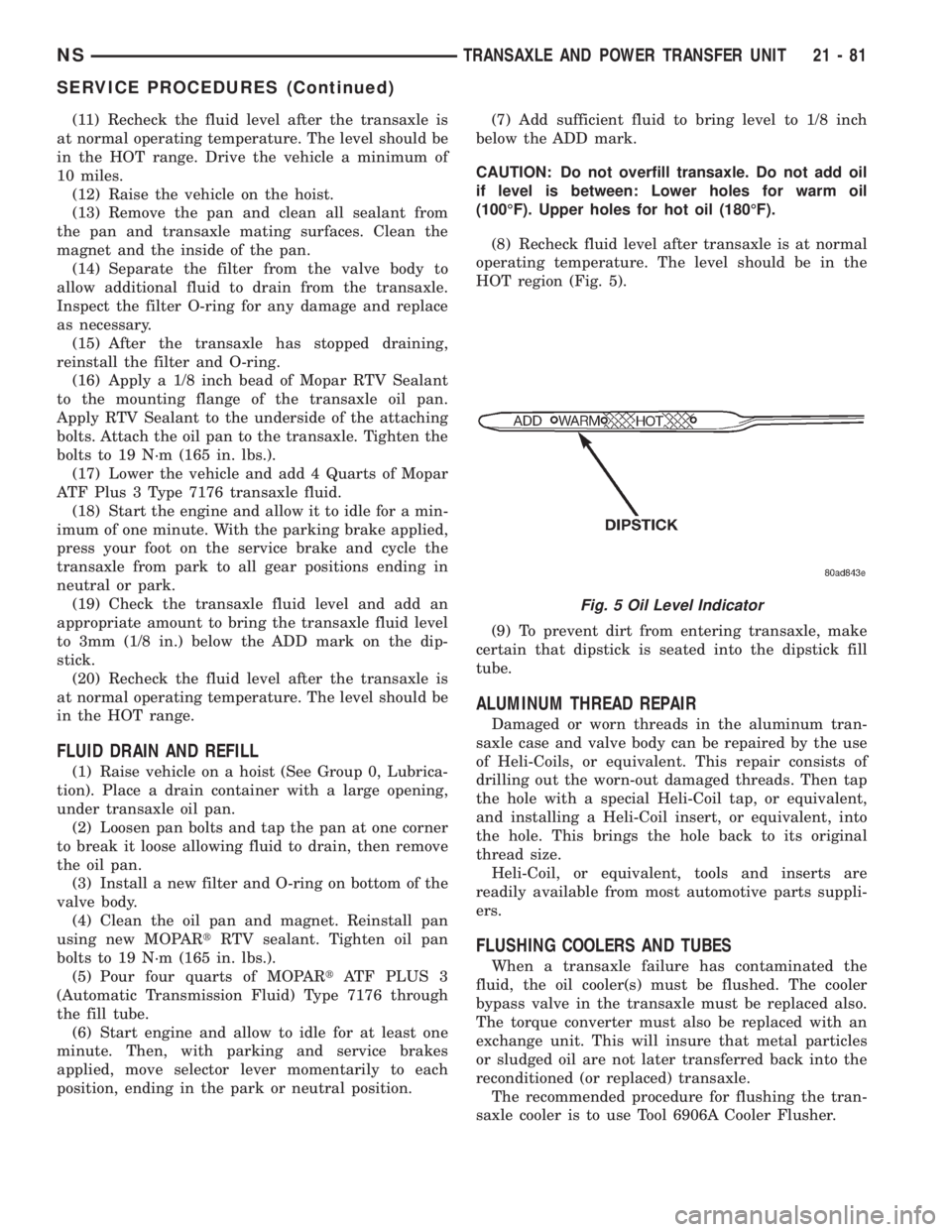
CAUTION: Do not overfill transaxle. Do not add oil
if level is between: Lower holes for warm oil
(100ÉF). Upper holes for hot oil (180ÉF).
(8) Recheck fluid level after transaxle is at normal
operating temperature. The level should be in the
HOT region (Fig. 5).
(9) To prevent dirt from entering transaxle, make
certain that dipstick is seated into the dipstick fill
tube.
ALUMINUM THREAD REPAIR
Damaged or worn threads in the aluminum tran-
saxle case and valve body can be repaired by the use
of Heli-Coils, or equivalent. This repair consists of
drilling out the worn-out damaged threads. Then tap
the hole with a special Heli-Coil tap, or equivalent,
and installing a Heli-Coil insert, or equivalent, into
the hole. This brings the hole back to its original
thread size.
Heli-Coil, or equivalent, tools and inserts are
readily available from most automotive parts suppli-
ers.
FLUSHING COOLERS AND TUBES
When a transaxle failure has contaminated the
fluid, the oil cooler(s) must be flushed. The cooler
bypass valve in the transaxle must be replaced also.
The torque converter must also be replaced with an
exchange unit. This will insure that metal particles
or sludged oil are not later transferred back into the
reconditioned (or replaced) transaxle.
The recommended procedure for flushing the tran-
saxle cooler is to use Tool 6906A Cooler Flusher.
Fig. 5 Oil Level Indicator
NSTRANSAXLE AND POWER TRANSFER UNIT 21 - 81
SERVICE PROCEDURES (Continued)
Page 1556 of 1938
WARNING: WEAR PROTECTIVE EYEWEAR THAT
MEETS THE REQUIREMENTS OF OSHA AND ANSI
Z87.1±1968. WEAR STANDARD INDUSTRIAL RUB-
BER GLOVES.
KEEP LIGHTED CIGARETTES, SPARKS, FLAMES,
AND OTHER IGNITION SOURCES AWAY FROM THE
AREA TO PREVENT THE IGNITION OF COMBUSTI-
BLE LIQUIDS AND GASES. KEEP A CLASS (B) FIRE
EXTINGUISHER IN THE AREA WHERE THE
FLUSHER WILL BE USED.
KEEP THE AREA WELL VENTILATED.
DO NOT LET FLUSHING SOLVENT COME IN CON-
TACT WITH YOUR EYES OR SKIN: IF EYE CONTAM-
INATION OCCURS, FLUSH EYES WITH WATER FOR
15 TO 20 SECONDS. REMOVE CONTAMINATED
CLOTHING AND WASH AFFECTED SKIN WITH
SOAP AND WATER. SEEK MEDICAL ATTENTION.
COOLER FLUSH USING TOOL 6906A
(1) Remove cover plate filler plug on Tool 6906A.
Fill reservoir 1/2 to 3/4 full of fresh flushing solution.
Flushing solvents are petroleum based solutions gen-
erally used to clean automatic transmission compo-
nents.DO NOTuse solvents containing acids, water,
gasoline, or any other corrosive liquids.
(2) Reinstall filler plug on Tool 6906A.
(3) Verify pump power switch is turned OFF. Con-
nect red alligator clip to positive (+) battery post.
Connect black (-) alligator clip to a good ground.
(4) Disconnect the cooler lines at the transmission.
NOTE: When flushing transmission cooler and
lines, ALWAYS reverse flush.
(5) Connect the BLUE pressure line to the OUT-
LET (From) cooler line.
(6) Connect the CLEAR return line to the INLET
(To) cooler line
(7) Turn pump ON for two to three minutes to
flush cooler(s) and lines. Monitor pressure readings
and clear return lines. Pressure readings should sta-
bilize below 20 psi. for vehicles equipped with a sin-
gle cooler and 30 psi. for vehicles equipped with dual
coolers. If flow is intermittent or exceeds these pres-
sures, replace cooler.
(8) Turn pump OFF.
(9) Disconnect CLEAR suction line from reservoir
at cover plate. Disconnect CLEAR return line at
cover plate, and place it in a drain pan.
(10) Turn pump ON for 30 seconds to purge flush-
ing solution from cooler and lines. Turn pump OFF.
(11) Place CLEAR suction line into a one quart
container of MopartATF PLUS 3 Type 7176 auto-
matic transmission fluid.
(12) Turn pump ON until all transmission fluid is
removed from the one quart container and lines. Thispurges any residual cleaning solvent from the trans-
mission cooler and lines. Turn pump OFF.
(13) Disconnect alligator clips from battery. Recon-
nect flusher lines to cover plate, and remove flushing
adapters from cooler lines.
OIL PUMP VOLUME CHECK
After the new or repaired transmission has been
installed, fill to the proper level with Mopar ATF
PLUS 3 (Type 7176) automatic transmission fluid.
The volume should be checked using the following
procedure:
(1) Disconnect theFrom coolerline at the trans-
mission and place a collecting container under the
disconnected line.
CAUTION: With the fluid set at the proper level,
fluid collection should not exceed (1) quart or inter-
nal damage to the transmission may occur.
(2) Run the engineat curb idle speed, with the
shift selector in neutral.
(3) If fluid flow is intermittent or it takes more
than 20 seconds to collect one quart of ATF, discon-
nect theTo Coolerline at the transaxle.
(4) Refill the transaxle to proper level and recheck
pump volume.
(5) If flow is found to be within acceptable limits,
replace the cooler. Then fill transmission to the
proper level, using Mopar ATF PLUS 3 (Type 7176)
automatic transmission fluid.
(6) If fluid flow is still found to be inadequate,
check the line pressure using the Transaxle Hydrau-
lic Pressure Test procedure.
(7) Check the cooler for debris on the external sur-
faces. Clean as necessary.
TRANSAXLE QUICK LEARN PROCEDURE
The quick learn procedure requires the use of the
DRBIII scan tool.
This program allows the electronic transaxle sys-
tem to recalibrate itself. This will provide the best
possible transaxle operation. The quick learn proce-
dure should be performed if any of the following pro-
cedures are performed:
²Transaxle Assembly Replacement
²Transmission Control Module Replacement
²Solenoid Pack Replacement
²Clutch Plate and/or Seal Replacement
²Valve Body Replacement or Recondition
To perform the Quick Learn Procedure, the follow-
ing conditions must be met:
²The brakes must be applied
²The engine speed must be above 500 rpm
²The throttle angle (TPS) must be less than 3
degrees
21 - 82 TRANSAXLE AND POWER TRANSFER UNITNS
SERVICE PROCEDURES (Continued)
Page 1632 of 1938
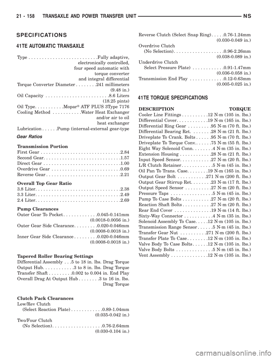
SPECIFICATIONS
41TE AUTOMATIC TRANSAXLE
Type..........................Fully adaptive,
electronically controlled,
four speed automatic with
torque converter
and integral differential
Torque Converter Diameter........241 millimeters
(9.48 in.)
Oil Capacity........................8.6 Liters
(18.25 pints)
OilType...........MopartATF PLUS 3Type 7176
Cooling Method...........Water Heat Exchanger
and/or air to oil
heat exchanger
Lubrication......Pump (internal-external gear-type
Gear Ratios
Transmission Portion
First Gear..............................2.84
Second Gear.............................1.57
Direct Gear.............................1.00
Overdrive Gear..........................0.69
Reverse Gear............................2.21
Overall Top Gear Ratio
3.8 Liter................................2.38
3.3 Liter................................2.49
2.4 Liter................................2.69
Pump Clearances
Outer Gear To Pocket.............0.045-0.141mm
(0.0018-0.0056 in.)
Outer Gear Side Clearance.........0.020-0.046mm
(0.0008-0.0018 in.)
Inner Gear Side Clearance.........0.020-0.046mm
(0.0008-0.0018 in.)
Tapered Roller Bearing Settings
Differential Assembly . . .5 to 18 in. lbs. Drag Torque
Output Hub............3to8in.lbs. Drag Torque
Transfer Shaft.........0.002 to 0.004 in. End Play
Overall Drag At Output Hub........3to16in.lbs.
Drag Torque
Clutch Pack Clearances
Low/Rev Clutch
(Select Reaction Plate)............0.89-1.04mm
(0.035-0.042 in.)
Two/Four Clutch
(No Selection)...................0.76-2.64mm
(0.030-0.104 in.)Reverse Clutch (Select Snap Ring).....0.76-1.24mm
(0.030-0.049 in.)
Overdrive Clutch
(No Selection)...................0.96-2.26mm
(0.038-0.089 in.)
Underdrive Clutch
Select Pressure Plate)............0.91-1.47mm
(0.036-0.058 in.)
Transmission End Play.............0.12-0.63mm
(0.005-0.025 in.)
41TE TORQUE SPECIFICATIONS
DESCRIPTION TORQUE
Cooler Line Fittings..........12N´m(105 in. lbs.)
Differential Cover............19N´m(165 in. lbs.)
Differential Ring Gear.........95N´m(70ft.lbs.)
Differential Bearing Ret........28N´m(21ft.lbs.)
Driveplate To Crank. Bolts......95N´m(70ft.lbs.)
Driveplate To Torque Conv.......75N´m(55ft.lbs.)
Eight Way Solenoid Conn........4N´m(35in.lbs.)
Extension Housing............28N´m(21ft.lbs.)
Input Speed Sensor............27N´m(20ft.lbs.)
L/R Clutch Retainer............5N´m(45in.lbs.)
Oil Pan To Trans. Case........19N´m(165 in. lbs.)
Output Gear Bolt...........271 N´m (200 ft. lbs.)
Output Gear Stirrup Ret........23N´m(17ft.lbs.)
Output Speed Sensor..........27N´m(20ft.lbs.)
Pressure Taps................5N´m(45in.lbs.)
Pump To Case Bolts...........27N´m(20ft.lbs.)
Reaction Shaft Bolts...........27N´m(20ft.lbs.)
Rear End Cover..............19N´m(14ft.lbs.)
Sixty-Way Connector...........4N´m(35in.lbs.)
Solenoid Assembly To Case.....12N´m(105 in. lbs.)
Transmission Range Sensor......5N´m(45in.lbs.)
Transfer Gear Nut..........271 N´m (200 ft. lbs.)
Transfer Plate To Case........12N´m(105 in. lbs.)
Valve Body To Case Bolts......12N´m(105 in. lbs.)
Valve Body Bolts..............5N´m(45in.lbs.)
Vent Assembly..............12N´m(105 in. lbs.)
21 - 158 TRANSAXLE AND POWER TRANSFER UNITNS
Page 1641 of 1938
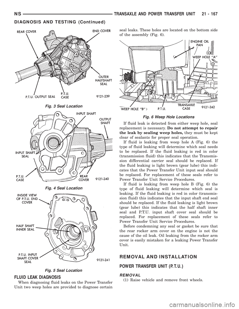
FLUID LEAK DIAGNOSIS
When diagnosing fluid leaks on the Power Transfer
Unit two weep holes are provided to diagnose certainseal leaks. These holes are located on the bottom side
of the assembly (Fig. 6).
If fluid leak is detected from either weep hole, seal
replacement is necessary.Do not attempt to repair
the leak by sealing weep holes,they must be kept
clear of sealants for proper seal operation.
If fluid is leaking from weep hole A (Fig. 6) the
type of fluid leaking will determine which seal needs
to be replaced. If the fluid leaking is red in color
(transmission fluid) this indicates that the Transmis-
sion differential carrier seal should be replaced. If
the fluid leaking is light brown (gear lube) this indi-
cates that the Power Transfer Unit input seal should
be replaced. For replacement of these seals refer to
Power Transfer Unit Service Procedures.
If fluid is leaking from weep hole B (Fig. 6) the
type of fluid leaking will determine which seal is
leaking. If the fluid leaking is red in color (transmis-
sion fluid) this indicates that the input shaft end seal
should be replaced. If the fluid leaking is light brown
(gear lube) this indicates that the half shaft inner
seal and P.T.U. input shaft cover seal should be
replaced. For replacement of these seals refer to
Power Transfer Unit Service Procedures.
Before condemning any seal or gasket be sure that
the rear rocker arm cover on the engine is not the
cause of the oil leak. Oil leaking from the rocker arm
cover is easily mistaken for a leaking Power Transfer
Unit.
REMOVAL AND INSTALLATION
POWER TRANSFER UNIT (P.T.U.)
REMOVAL
(1) Raise vehicle and remove front wheels.
Fig. 3 Seal Location
Fig. 4 Seal Location
Fig. 5 Seal Location
Fig. 6 Weep Hole Locations
NSTRANSAXLE AND POWER TRANSFER UNIT 21 - 167
DIAGNOSIS AND TESTING (Continued)
Page 1818 of 1938
GENERAL INFORMATION
INTRODUCTION
Both the heater and the heater/air conditioning
systems share many of the same components. This
group will deal with both systems together when
component function is common, and separately when
they are not.
For proper operation of the instrument panel con-
trols, refer to the Owner's Manual provided with the
vehicle.
All vehicles are equipped with a common A/C-
heater unit housing assembly. When the vehicle has
only a heater system, the evaporator and recirculat-
ing air door are omitted.
An optional zone control HVAC unit is available.
This unit has dual blend-air doors that can be regu-
lated independently of each other. The temperature
setting can be different from driver's side to passen-
ger side. There is also a rear (aux.) heating and A/C
system available when the vehicle is equipped with
zone control.
SAFETY PRECAUTIONS AND WARNINGS
WARNING: WEAR EYE PROTECTION WHEN SER-
VICING THE AIR CONDITIONING REFRIGERANT
SYSTEM. SERIOUS EYE INJURY CAN RESULT
FROM EYE CONTACT WITH REFRIGERANT. IF EYE
CONTACT IS MADE, SEEK MEDICAL ATTENTION
IMMEDIATELY.
DO NOT EXPOSE REFRIGERANT TO OPEN
FLAME. POISONOUS GAS IS CREATED WHEN
REFRIGERANT IS BURNED. AN ELECTRONIC TYPE
LEAK DETECTOR IS RECOMMENDED.
LARGE AMOUNTS OF REFRIGERANT RELEASED
IN A CLOSED WORK AREA WILL DISPLACE THE
OXYGEN AND CAUSE SUFFOCATION.
THE EVAPORATION RATE OF REFRIGERANT AT
AVERAGE TEMPERATURE AND ALTITUDE IS
EXTREMELY HIGH. AS A RESULT, ANYTHING THAT
COMES IN CONTACT WITH THE REFRIGERANT
WILL FREEZE. ALWAYS PROTECT SKIN OR DELI-
CATE OBJECTS FROM DIRECT CONTACT WITH
REFRIGERANT. R-134a SERVICE EQUIPMENT OR
VEHICLE A/C SYSTEM SHOULD NOT BE PRES-
SURE TESTED OR LEAK TESTED WITH COM-
PRESSED AIR.
SOME MIXTURES OF AIR and R-134a HAVE BEEN
SHOWN TO BE COMBUSTIBLE AT ELEVATED
PRESSURES. THESE MIXTURES ARE POTENTIALLY
DANGEROUS AND MAY RESULT IN FIRE OR
EXPLOSION CAUSING INJURY OR PROPERTY
DAMAGE.
ANTIFREEZE IS AN ETHYLENE GLYCOL BASE
COOLANT AND IS HARMFUL IF SWALLOWED ORINHALED. SEEK MEDICAL ATTENTION IMMEDI-
ATELY IF SWALLOWED OR INHALED. DO NOT
STORE IN OPEN OR UNMARKED CONTAINERS.
WASH SKIN AND CLOTHING THOROUGHLY AFTER
COMING IN CONTACT WITH ETHYLENE GLYCOL.
KEEP OUT OF REACH OF CHILDREN AND PETS.
DO NOT OPEN A COOLING SYSTEM WHEN THE
ENGINE IS AT RUNNING TEMPERATURE. PER-
SONAL INJURY CAN RESULT.
CAUTION: The engine cooling system is designed
to develop internal pressure of 97 to 123 kPa (14 to
18 psi). Allow the vehicle to cool a minimum of 15
minutes before opening the cooling system. Refer
to Group 7, Cooling System.
DESCRIPTION AND OPERATION
AIR DISTRIBUTION DUCTS
The air distribution ducts for the A/C, Heater,
Defroster, and Second Seating Air Distribution are
not serviceable in vehicle. The procedures for service
of these ducts are covered in Group 8E, Instrument
Panel and Gauges.
The only ducts that are serviceable in the vehicle
are the side window demister ducts and the ducts
that feed the front door outlets for the first rear pas-
senger(s) seating. To service the door ducts refer to
Group 23, Body.
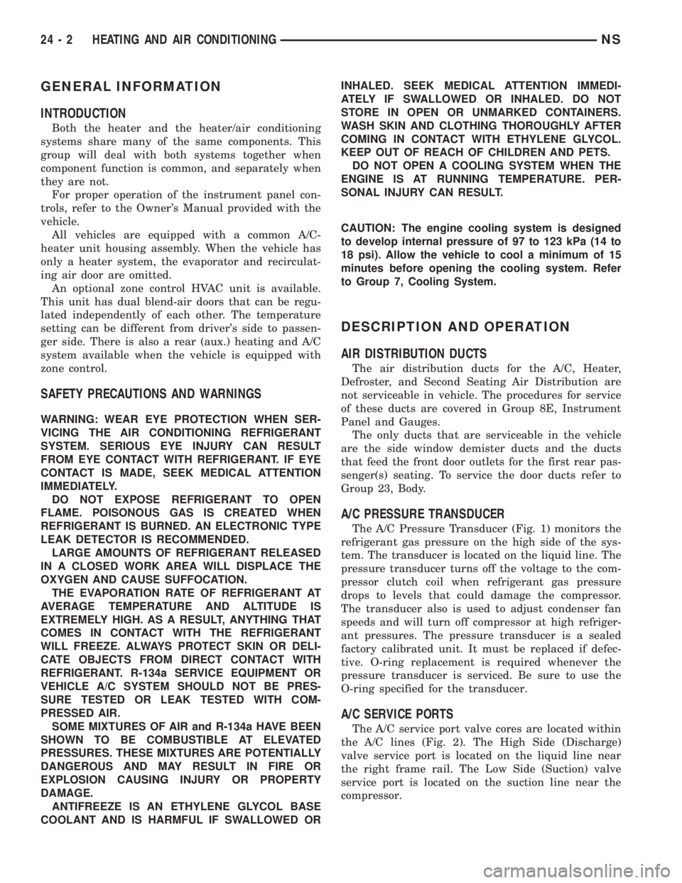
A/C PRESSURE TRANSDUCER
The A/C Pressure Transducer (Fig. 1) monitors the
refrigerant gas pressure on the high side of the sys-
tem. The transducer is located on the liquid line. The
pressure transducer turns off the voltage to the com-
pressor clutch coil when refrigerant gas pressure
drops to levels that could damage the compressor.
The transducer also is used to adjust condenser fan
speeds and will turn off compressor at high refriger-
ant pressures. The pressure transducer is a sealed
factory calibrated unit. It must be replaced if defec-
tive. O-ring replacement is required whenever the
pressure transducer is serviced. Be sure to use the
O-ring specified for the transducer.
A/C SERVICE PORTS
The A/C service port valve cores are located within
the A/C lines (Fig. 2). The High Side (Discharge)
valve service port is located on the liquid line near
the right frame rail. The Low Side (Suction) valve
service port is located on the suction line near the
compressor.
24 - 2 HEATING AND AIR CONDITIONINGNS
Page 1821 of 1938
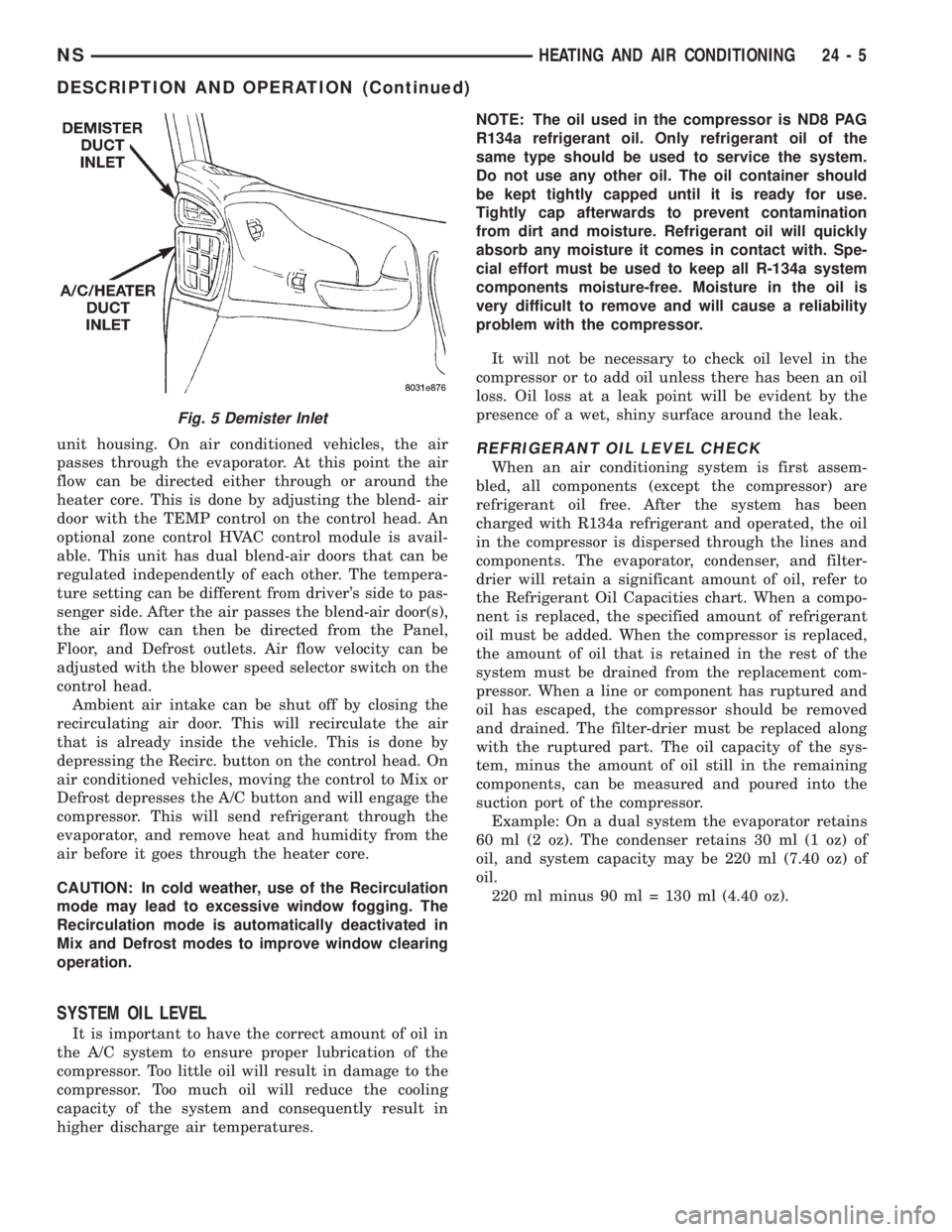
unit housing. On air conditioned vehicles, the air
passes through the evaporator. At this point the air
flow can be directed either through or around the
heater core. This is done by adjusting the blend- air
door with the TEMP control on the control head. An
optional zone control HVAC control module is avail-
able. This unit has dual blend-air doors that can be
regulated independently of each other. The tempera-
ture setting can be different from driver's side to pas-
senger side. After the air passes the blend-air door(s),
the air flow can then be directed from the Panel,
Floor, and Defrost outlets. Air flow velocity can be
adjusted with the blower speed selector switch on the
control head.
Ambient air intake can be shut off by closing the
recirculating air door. This will recirculate the air
that is already inside the vehicle. This is done by
depressing the Recirc. button on the control head. On
air conditioned vehicles, moving the control to Mix or
Defrost depresses the A/C button and will engage the
compressor. This will send refrigerant through the
evaporator, and remove heat and humidity from the
air before it goes through the heater core.
CAUTION: In cold weather, use of the Recirculation
mode may lead to excessive window fogging. The
Recirculation mode is automatically deactivated in
Mix and Defrost modes to improve window clearing
operation.
SYSTEM OIL LEVEL
It is important to have the correct amount of oil in
the A/C system to ensure proper lubrication of the
compressor. Too little oil will result in damage to the
compressor. Too much oil will reduce the cooling
capacity of the system and consequently result in
higher discharge air temperatures.NOTE: The oil used in the compressor is ND8 PAG
R134a refrigerant oil. Only refrigerant oil of the
same type should be used to service the system.
Do not use any other oil. The oil container should
be kept tightly capped until it is ready for use.
Tightly cap afterwards to prevent contamination
from dirt and moisture. Refrigerant oil will quickly
absorb any moisture it comes in contact with. Spe-
cial effort must be used to keep all R-134a system
components moisture-free. Moisture in the oil is
very difficult to remove and will cause a reliability
problem with the compressor.
It will not be necessary to check oil level in the
compressor or to add oil unless there has been an oil
loss. Oil loss at a leak point will be evident by the
presence of a wet, shiny surface around the leak.
REFRIGERANT OIL LEVEL CHECK
When an air conditioning system is first assem-
bled, all components (except the compressor) are
refrigerant oil free. After the system has been
charged with R134a refrigerant and operated, the oil
in the compressor is dispersed through the lines and
components. The evaporator, condenser, and filter-
drier will retain a significant amount of oil, refer to
the Refrigerant Oil Capacities chart. When a compo-
nent is replaced, the specified amount of refrigerant
oil must be added. When the compressor is replaced,
the amount of oil that is retained in the rest of the
system must be drained from the replacement com-
pressor. When a line or component has ruptured and
oil has escaped, the compressor should be removed
and drained. The filter-drier must be replaced along
with the ruptured part. The oil capacity of the sys-
tem, minus the amount of oil still in the remaining
components, can be measured and poured into the
suction port of the compressor.
Example: On a dual system the evaporator retains
60 ml (2 oz). The condenser retains 30 ml (1 oz) of
oil, and system capacity may be 220 ml (7.40 oz) of
oil.
220 ml minus 90 ml = 130 ml (4.40 oz).
Fig. 5 Demister Inlet
NSHEATING AND AIR CONDITIONING 24 - 5
DESCRIPTION AND OPERATION (Continued)