1996 CHRYSLER VOYAGER oil type
[x] Cancel search: oil typePage 1832 of 1938
TEMPERATURE CONTROL
If temperature cannot be adjusted with the TEMP
lever on the control panel, the following could require
service:
(1) Blend-air door binding.
(2) Faulty blend-air door motor.
(3) Improper engine coolant temperature.
(4) Faulty Instrument Panel Control.
SYSTEM CHARGE LEVEL TEST
The procedure below should be used to check
and/or fill the refrigerant charge in the air condition-
ing system.
NOTE: The amount of R134a refrigerant that the air
conditioning system holds is:
²Without rear A/C± .96 kg (34 oz. or 2.13 lbs.)
²With Rear A/C± 1.36 kg (48 oz. or 3.00 lbs.)
NOTE: Low Charge, condition may be described
as:
²Loss of A/C performance
²Fog from A/C outlets
²evaporator may have a HISS sound
There are two different ways the system can be
tested:
²With a scan tool (DRB), thermocouple and the
Charge Determination Graph. Use the scan tool
(DRB) diagnostic topic: Engine±System Monitors, A/C
Pressure.
²Using a manifold gauge set, a thermocouple and
the Charge Determination Graph.
It is recommended to use the gauges or reclaim/re-
cycle equipment.
WARNING: AVOID BREATHING A/C REFRIGERANT
AND LUBRICANT VAPOR OR MIST. EXPOSURE MAY
IRRITATE EYES, NOSE AND THROAT. USE ONLY
APPROVED SERVICE EQUIPMENT MEETING SAE
REQUIREMENTS TO DISCHARGE R-134a SYSTEM.
IF ACCIDENTAL SYSTEM DISCHARGE OCCURS,
VENTILATE WORK AREA BEFORE RESUMING SER-
VICE.
R-134a SERVICE EQUIPMENT OR VEHICLE A/C
SYSTEM SHOULD NOT BE PRESSURE TESTED OR
LEAK TESTED WITH COMPRESSED AIR. SOME
MIXTURES OF AIR/R-134a HAVE BEEN SHOWN TO
BE COMBUSTIBLE AT ELEVATED PRESSURES.
THESE MIXTURES ARE POTENTIALLY DANGER-
OUS AND MAY RESULT IN FIRE OR EXPLOSION
CAUSING INJURY OR PROPERTY DAMAGE.
(1) Establish your preferred method of measuring
liquid line pressure. Use a manifold gauge set or a
DRB scan tool.(2) Attach a clamp-on thermocouple (P.S.E. 66-324-
0014 or 80PK-1A) or equivalent to the liquid line. It
must be placed as close to the A/C Pressure Trans-
ducer as possible to observe liquid line temperature.
Refer to ªThermocouple Probeº in this section for
more information on probe.
(3) The vehicle must be in the following modes:
²Transaxle in Park
²Engine Idling at 700 rpm
²A/C Controls Set to Outside Air
²Panel Mode
²Full Cool
²High Blower motor, (vehicle equipped with rear
A/C turn rear blower motor ON HIGH)
²A/C Button in the ON position
²Vehicle Windows Open.
²Recirc. button turned OFF
(4) Operate system for a couple of minutes to allow
the system to stabilize.
(5) Set system pressure to about 1793 kPa (260
psi) by placing a piece of cardboard over part of the
front side of the condenser. To place cardboard prop-
erly, remove the upper radiator-condenser cover.
Insert cardboard between condenser and radiator
front. This will maintain a constant pressure.
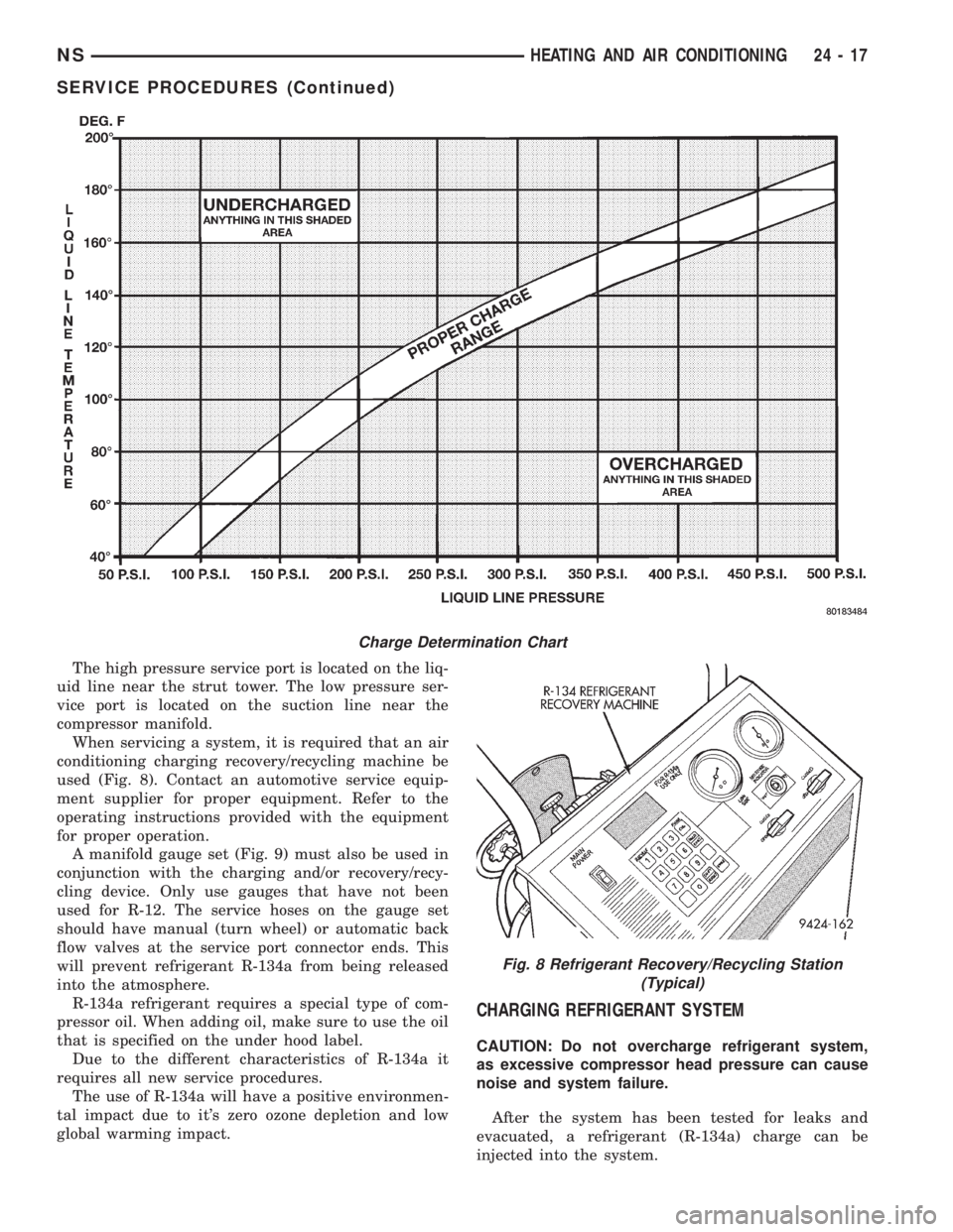
(6) Observe Liquid Line pressure and Liquid line
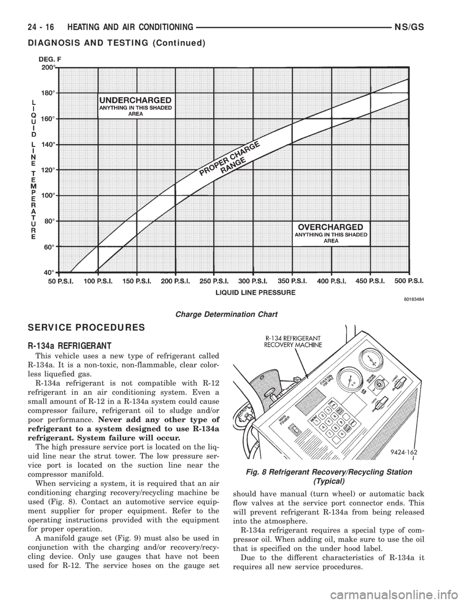
temperature. Using theCharge Determination
Chartdetermine where the system is currently oper-
ating. If the system is in the undercharged region,
ADD 0.057 Kg. (2 oz.) to the system and recheck
readings. If the system is in the overcharged region,
RECLAIM 0.057 Kg. (2 oz.) from the system and
recheck readings. Continue this process until the sys-
tem readings are in the proper charge area on the
Charge Determination Chart.
(7) The same procedure can be performed using
the scan tool (DRB). To determine liquid line pres-
sure, attach the scan tool, go to System Moni-
tors±A/C Pressure. Observe liquid line pressure from
A/C Pressure Transducer on digital display and digi-
tal thermometer. Refer toCharge Determination
Chartand determine where the system is operating.
SERVICE PROCEDURES
R-134a REFRIGERANT
This vehicle uses a new type of refrigerant called
R-134a. It is a non-toxic, non-flammable, clear color-
less liquefied gas.
R-134a refrigerant is not compatible with R-12
refrigerant in an air conditioning system. Even a
small amount of R-12 in a R-134a system could cause
compressor failure, refrigerant oil to sludge and/or
poor performance.Never add any other type of
refrigerant to a system designed to use R-134a
refrigerant. System failure will occur.
24 - 16 HEATING AND AIR CONDITIONINGNS
DIAGNOSIS AND TESTING (Continued)
Page 1833 of 1938
The high pressure service port is located on the liq-
uid line near the strut tower. The low pressure ser-
vice port is located on the suction line near the
compressor manifold.
When servicing a system, it is required that an air
conditioning charging recovery/recycling machine be
used (Fig. 8). Contact an automotive service equip-
ment supplier for proper equipment. Refer to the
operating instructions provided with the equipment
for proper operation.
A manifold gauge set (Fig. 9) must also be used in
conjunction with the charging and/or recovery/recy-
cling device. Only use gauges that have not been
used for R-12. The service hoses on the gauge set
should have manual (turn wheel) or automatic back
flow valves at the service port connector ends. This
will prevent refrigerant R-134a from being released
into the atmosphere.
R-134a refrigerant requires a special type of com-
pressor oil. When adding oil, make sure to use the oil
that is specified on the under hood label.
Due to the different characteristics of R-134a it
requires all new service procedures.
The use of R-134a will have a positive environmen-
tal impact due to it's zero ozone depletion and low
global warming impact.
CHARGING REFRIGERANT SYSTEM
CAUTION: Do not overcharge refrigerant system,
as excessive compressor head pressure can cause
noise and system failure.
After the system has been tested for leaks and
evacuated, a refrigerant (R-134a) charge can be
injected into the system.
Charge Determination Chart
Fig. 8 Refrigerant Recovery/Recycling Station
(Typical)
NSHEATING AND AIR CONDITIONING 24 - 17
SERVICE PROCEDURES (Continued)
Page 1835 of 1938
eliminate all moisture in system. When the suction
gauge reads -88 kPa (- 26 in. Hg) vacuum or greater
for 45 minutes, close all valves and turn off vacuum
pump. If the system fails to reach specified vacuum,
the refrigerant system likely has a leak that must be
corrected. If the refrigerant system maintains speci-
fied vacuum for at least 30 minutes, start the vac-
uum pump, open the suction and discharge valves.
Then allow the system to evacuate an additional 10
minutes.
(3) Close all valves. Turn off and disconnect the
vacuum pump.
(4) The refrigerant system is prepared to be
charged with refrigerant.
THERMOCOUPLE PROBE
To diagnose the A/C system, a temperature probe is
required to measure liquid line temperature. The
clamp-on type K probe shown in this manual is avail-
able through the Chrysler Professional Service
Equipment (PSE) program. This probe is compatible
with temperature-measuring instruments that accept
Type K Thermocouples and have a miniature connec-
tor input. Other temperature probes are available
through aftermarket sources. All references in this
manual will reflect the use of the probe made avail-
able through the Professional Service Equipment pro-
gram.
In order to use the temperature probe, a digital
thermometer will be required. If a digital thermome-
ter is not available, an adapter is available through
the Professional Service Equipment program. It can
convert any standard digital multimeter into a ther-
mometer. This adapter is designed to accept any
standard K-type thermocouple.
If a digital multimeter is not available, it to can be
ordered through Professional Service Equipment pro-
gram.
STICKING HVAC CONTROL MODULE PUSH
BUTTONS
To service HVAC control module push buttons that
are sticking, spray between the buttons with Mopart
MP-50. The MP-50 is a all purpose lubricant for
mechanical and electrical uses. After spraying around
the push buttons wipe any excess off the radio bezel
and HVAC control module push buttons. Operate the
buttons to ensure that they are operating freely.
SYSTEM LEAK CHECKING
WARNING: R-134a SERVICE EQUIPMENT OR VEHI-
CLE A/C SYSTEM SHOULD NOT BE PRESSURE
TESTED OR LEAK TESTED WITH COMPRESSED
AIR. SOME MIXTURES OF AIR/R-134a HAVE BEEN
SHOWN TO BE COMBUSTIBLE AT ELEVATEDPRESSURES. THESE MIXTURES ARE POTENTIALLY
DANGEROUS AND MAY RESULT IN FIRE OR
EXPLOSION CAUSING INJURY OR PROPERTY
DAMAGE.
If the A/C system is not cooling properly, determine
if the refrigerant system is fully charged with
R-134a. This is accomplished by performing a system
Charge Level-Check or Fill. If while performing this
test A/C liquid line pressure is less than 207 kPa (30
psi) proceed to Empty Refrigerant System Leak Test.
If liquid line pressure is greater than 207 kPa (30
psi) proceed to low refrigerant level leak test. If the
refrigerant system is empty or low in refrigerant
charge, a leak at any line fitting or component seal is
likely. A review of the fittings, lines and components
for oily residue is an indication of the leak location.
To detect a leak in the refrigerant system, perform
one of the following procedures as indicated by the
symptoms.
WARNING: AVOID BREATHING A/C REFRIGERANT
AND LUBRICANT VAPOR OR MIST. EXPOSURE MAY
IRRITATE EYES, NOSE AND THROAT. USE ONLY
APPROVED SERVICE EQUIPMENT MEETING SAE
REQUIREMENTS TO DISCHARGE R-134a SYSTEM.
IF ACCIDENTAL SYSTEM DISCHARGE OCCURS,
VENTILATE WORK AREA BEFORE RESUMING SER-
VICE.
EMPTY REFRIGERANT SYSTEM LEAK TEST
(1) Evacuate the refrigerant system to the lowest
degree of vacuum possible (about 28 in Hg.). Deter-
mine if the system holds a vacuum for 15 minutes. If
vacuum is held, a leak is probably not present. If sys-
tem will not maintain vacuum level, proceed with
this procedure.
(2) Prepare a .284 Kg. (10 oz.) refrigerant charge
to be injected into the system.
(3) Connect and dispense .284 Kg. (10 oz.) of
refrigerant into the evacuated refrigerant system.
(4) Proceed to step two of Low Refrigerant Level
Leak Test.
LOW REFRIGERANT LEVEL LEAK TEST
(1) Determine if there is any (R-134a) refrigerant
in the system. Use the scan tool (DRB) under the
menu Systems Sensors±A/C Pressure test or pressure
gauge liquid line temperature partial charge check.
See system charge level check or fill for procedure.
(2) Position the vehicle in a wind free work area.
This will aid in detecting small leaks.
(3) Bring the refrigerant system up to operating
temperature and pressure. This is done by allowing
the engine to run for five minutes with the system
set to the following:
NSHEATING AND AIR CONDITIONING 24 - 19
SERVICE PROCEDURES (Continued)
Page 1836 of 1938
²Transaxle in Park
²Engine Idling at 700 rpm
²A/C Controls Set in 100 percent outside air
²Full Panel Mode
²Blower motor ON HIGH
²A/C in the ON position
²Front Windows Open.
²Rear Air Off (If Equipped)
CAUTION: A leak detector designed for R-12 refrig-
erant will not detect leaks in a R-134a refrigerant
system.
(4) Shut off the vehicle and wait 2 to 7 minutes.
Then use an Electronic Leak Detector that is
designed to detect R-134a type refrigerant and search
for leaks. Fittings, lines, or components that appear
to be oily usually indicates a refrigerant leak. To
inspect the evaporator core for leaks, insert the leak
detector probe into the recirculating air door opening
or a heat duct.
If a thorough leak check has been completed with-
out indication of a leak, proceed to System Charge
Level-Check or Fill.
REMOVAL AND INSTALLATION
A/C PRESSURE TRANSDUCER
REMOVAL
(1) Disconnect the wire connector at the pressure
transducer.
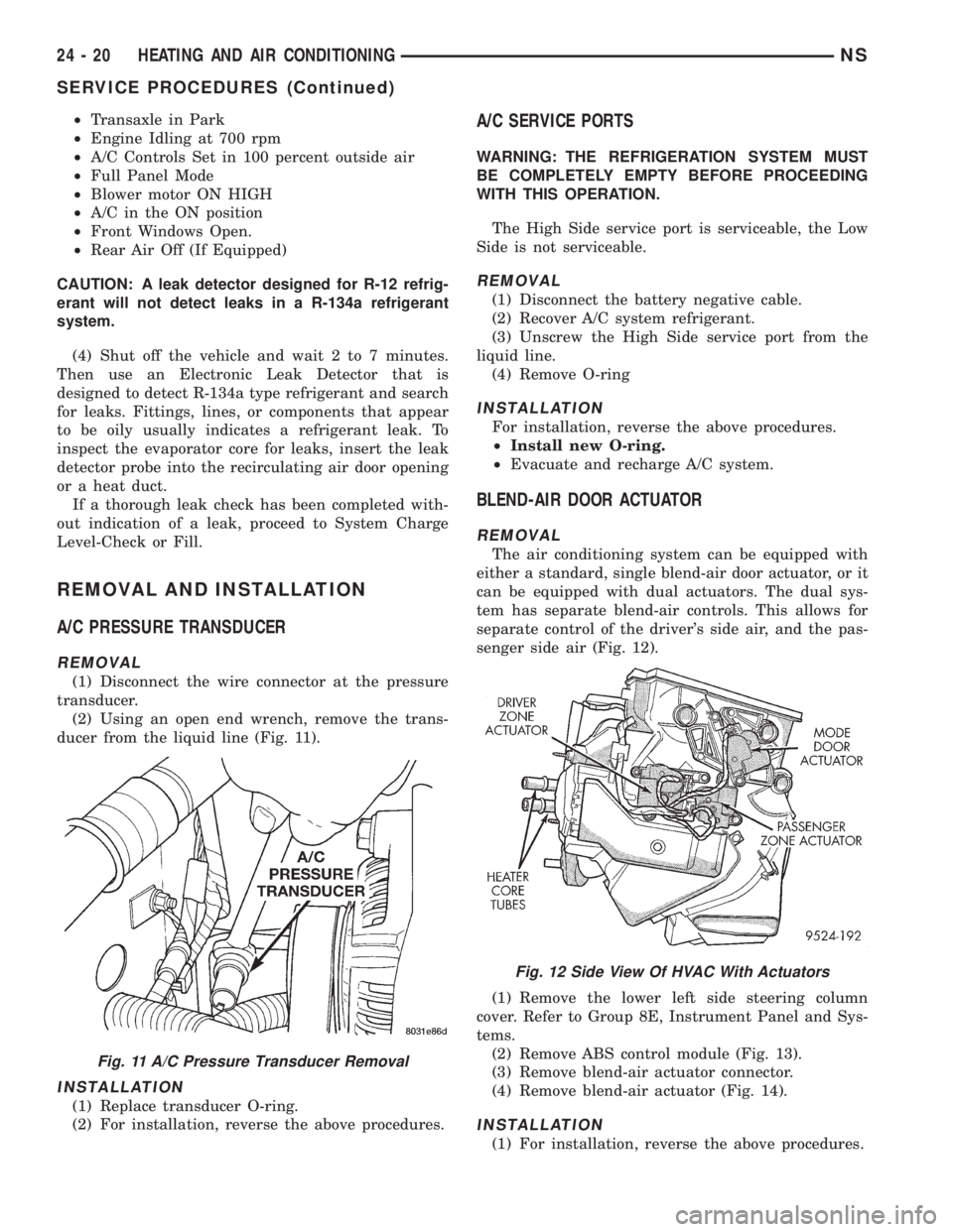
(2) Using an open end wrench, remove the trans-
ducer from the liquid line (Fig. 11).
INSTALLATION
(1) Replace transducer O-ring.
(2) For installation, reverse the above procedures.
A/C SERVICE PORTS
WARNING: THE REFRIGERATION SYSTEM MUST
BE COMPLETELY EMPTY BEFORE PROCEEDING
WITH THIS OPERATION.
The High Side service port is serviceable, the Low
Side is not serviceable.
REMOVAL
(1) Disconnect the battery negative cable.
(2) Recover A/C system refrigerant.
(3) Unscrew the High Side service port from the
liquid line.
(4) Remove O-ring
INSTALLATION
For installation, reverse the above procedures.
²Install new O-ring.
²Evacuate and recharge A/C system.
BLEND-AIR DOOR ACTUATOR
REMOVAL
The air conditioning system can be equipped with
either a standard, single blend-air door actuator, or it
can be equipped with dual actuators. The dual sys-
tem has separate blend-air controls. This allows for
separate control of the driver's side air, and the pas-
senger side air (Fig. 12).
(1) Remove the lower left side steering column
cover. Refer to Group 8E, Instrument Panel and Sys-
tems.
(2) Remove ABS control module (Fig. 13).
(3) Remove blend-air actuator connector.
(4) Remove blend-air actuator (Fig. 14).
INSTALLATION
(1) For installation, reverse the above procedures.
Fig. 11 A/C Pressure Transducer Removal
Fig. 12 Side View Of HVAC With Actuators
24 - 20 HEATING AND AIR CONDITIONINGNS
SERVICE PROCEDURES (Continued)
Page 1839 of 1938
COMPRESSOR
REMOVAL
WARNING: REFER TO REFRIGERANT SERVICE
PROCEDURES FOR INFORMATION REGARDING
PROPER RECOVERY OF THE REFRIGERANT
BEFORE ATTEMPTING TO REMOVE THE COM-
PRESSOR.
(1) Disconnect negative battery cable.
(2) Pinch off coolant lines to rear Heat unit (if
equipped). Drain engine coolant.
(3) Remove upper radiator hose.
(4) Remove drive belt (refer to Group 7, Cooling
System). Disconnect compressor clutch wire lead.
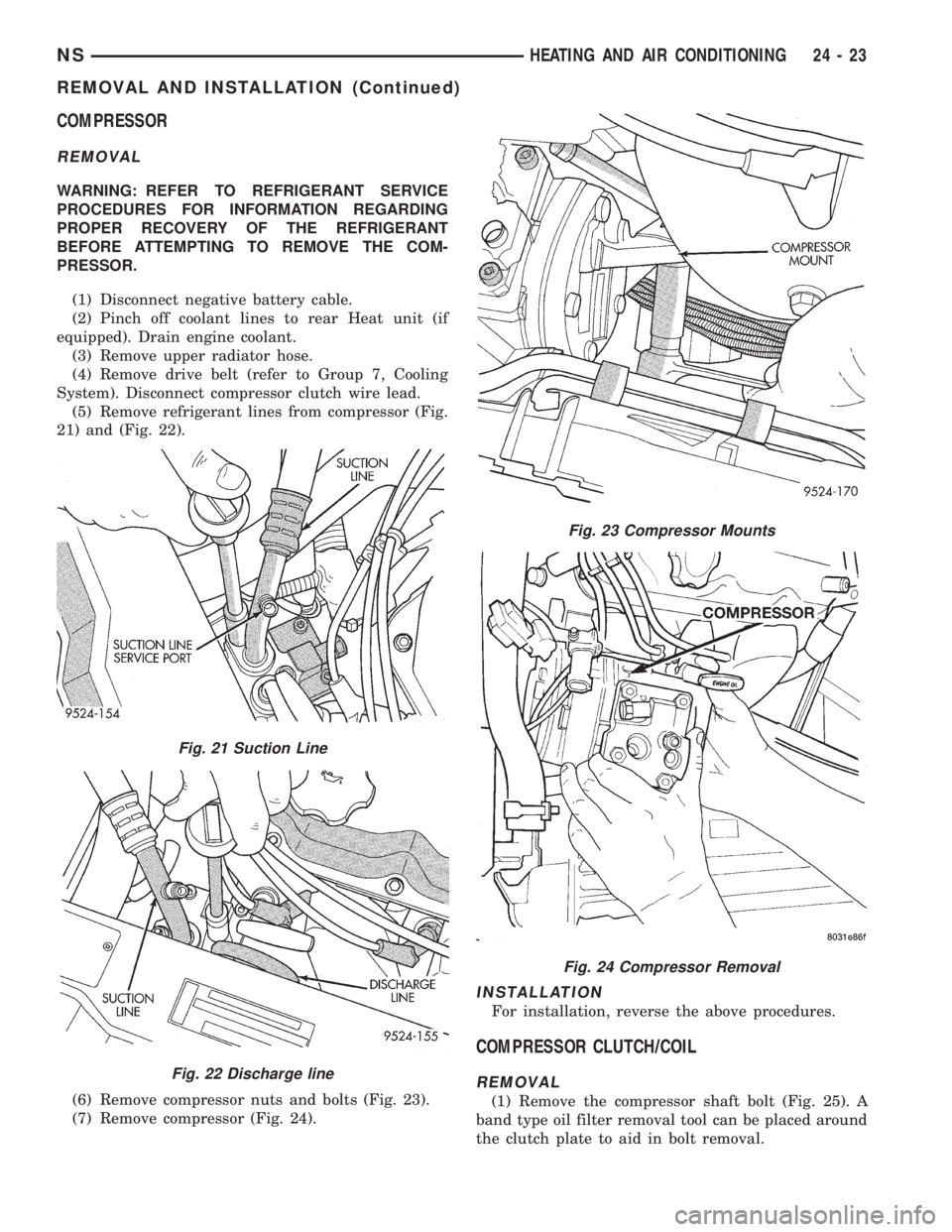
(5) Remove refrigerant lines from compressor (Fig.
21) and (Fig. 22).
(6) Remove compressor nuts and bolts (Fig. 23).
(7) Remove compressor (Fig. 24).
INSTALLATION
For installation, reverse the above procedures.
COMPRESSOR CLUTCH/COIL
REMOVAL
(1) Remove the compressor shaft bolt (Fig. 25). A
band type oil filter removal tool can be placed around
the clutch plate to aid in bolt removal.
Fig. 21 Suction Line
Fig. 22 Discharge line
Fig. 23 Compressor Mounts
Fig. 24 Compressor Removal
NSHEATING AND AIR CONDITIONING 24 - 23
REMOVAL AND INSTALLATION (Continued)
Page 1868 of 1938
SAFETY PRECAUTIONS AND WARNINGS
WARNING: WEAR EYE PROTECTION WHEN SER-
VICING THE AIR CONDITIONING REFRIGERANT
SYSTEM. SERIOUS EYE INJURY CAN RESULT
FROM EYE CONTACT WITH REFRIGERANT. IF EYE
CONTACT IS MADE, SEEK MEDICAL ATTENTION
IMMEDIATELY.
DO NOT EXPOSE REFRIGERANT TO OPEN
FLAME. POISONOUS GAS IS CREATED WHEN
REFRIGERANT IS BURNED. AN ELECTRONIC TYPE
LEAK DETECTOR IS RECOMMENDED.
LARGE AMOUNTS OF REFRIGERANT RELEASED
IN A CLOSED WORK AREA WILL DISPLACE THE
OXYGEN AND CAUSE SUFFOCATION.
THE EVAPORATION RATE OF REFRIGERANT AT
AVERAGE TEMPERATURE AND ALTITUDE IS
EXTREMELY HIGH. AS A RESULT, ANYTHING THAT
COMES IN CONTACT WITH THE REFRIGERANT
WILL FREEZE. ALWAYS PROTECT SKIN OR DELI-
CATE OBJECTS FROM DIRECT CONTACT WITH
REFRIGERANT. R-134a SERVICE EQUIPMENT OR
VEHICLE A/C SYSTEM SHOULD NOT BE PRES-
SURE TESTED OR LEAK TESTED WITH COM-
PRESSED AIR.
SOME MIXTURES OF AIR and R-134a HAVE BEEN
SHOWN TO BE COMBUSTIBLE AT ELEVATED
PRESSURES. THESE MIXTURES ARE POTENTIALLY
DANGEROUS AND MAY RESULT IN FIRE OR
EXPLOSION CAUSING INJURY OR PROPERTY
DAMAGE.
ANTIFREEZE IS AN ETHYLENE GLYCOL BASE
COOLANT AND IS HARMFUL IF SWALLOWED OR
INHALED. SEEK MEDICAL ATTENTION IMMEDI-
ATELY IF SWALLOWED OR INHALED. DO NOT
STORE IN OPEN OR UNMARKED CONTAINERS.
WASH SKIN AND CLOTHING THOROUGHLY AFTER
COMING IN CONTACT WITH ETHYLENE GLYCOL.
KEEP OUT OF REACH OF CHILDREN AND PETS.
DO NOT OPEN A COOLING SYSTEM WHEN THE
ENGINE IS AT RUNNING TEMPERATURE. PER-
SONAL INJURY CAN RESULT.
CAUTION: The engine cooling system is designed
to develop internal pressure of 97 to 123 kPa (14 to
18 psi). Allow the vehicle to cool a minimum of 15
minutes before opening the cooling system. Refer
to Group 7, Cooling System.
DESCRIPTION AND OPERATION
AIR DISTRIBUTION DUCTS
The air distribution ducts for the A/C, Heater,
Defroster, and Second Seating Air Distribution arenot serviceable in vehicle. The procedures for service
of these ducts are covered in Group 8E, Instrument
Panel and Gauges.
The only ducts that are serviceable in the vehicle
are the side window demister ducts and the ducts
that feed the front door outlets for the first rear pas-
senger(s) seating. To service the door ducts refer to
Group 23, Body.
A/C PRESSURE TRANSDUCER
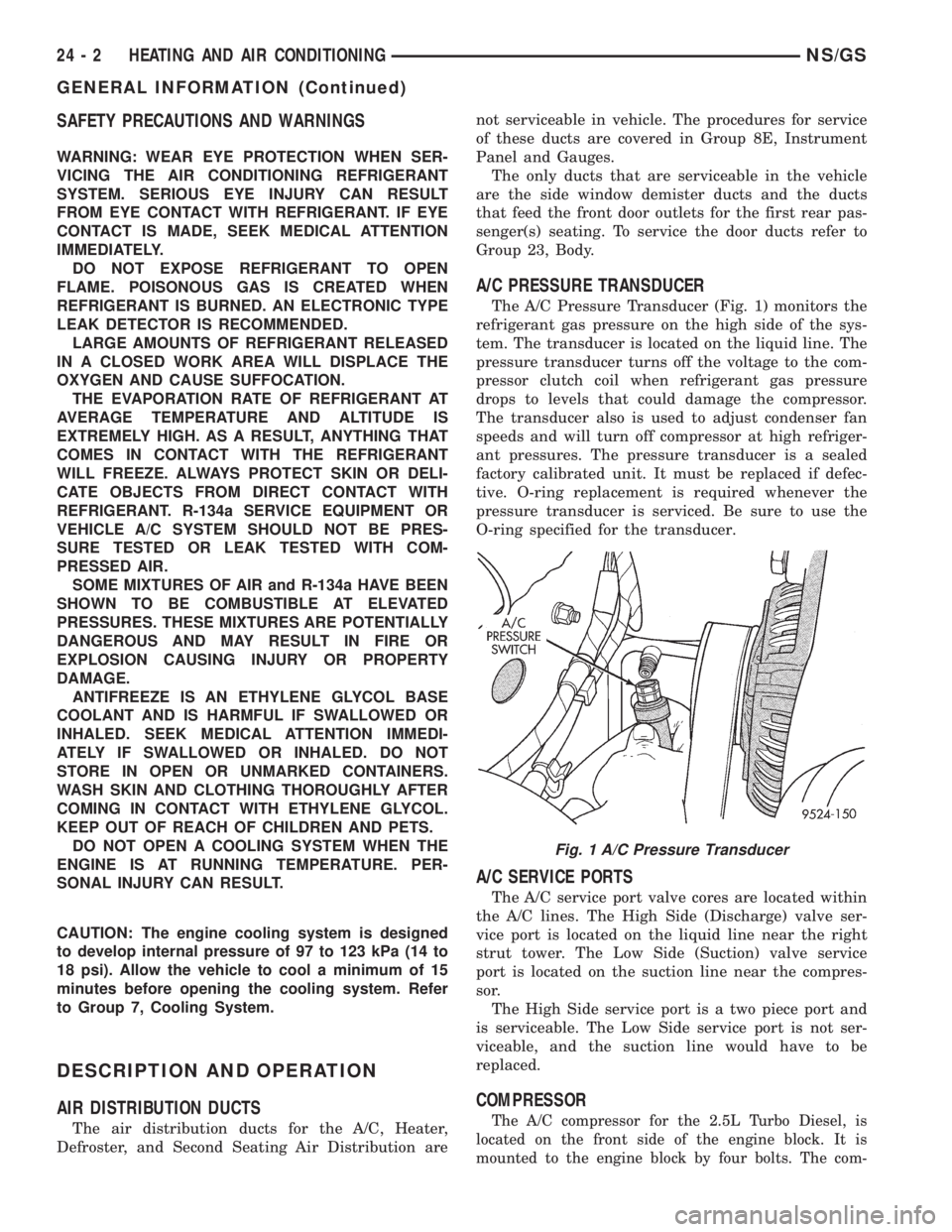
The A/C Pressure Transducer (Fig. 1) monitors the
refrigerant gas pressure on the high side of the sys-
tem. The transducer is located on the liquid line. The
pressure transducer turns off the voltage to the com-
pressor clutch coil when refrigerant gas pressure
drops to levels that could damage the compressor.
The transducer also is used to adjust condenser fan
speeds and will turn off compressor at high refriger-
ant pressures. The pressure transducer is a sealed
factory calibrated unit. It must be replaced if defec-
tive. O-ring replacement is required whenever the
pressure transducer is serviced. Be sure to use the
O-ring specified for the transducer.
A/C SERVICE PORTS
The A/C service port valve cores are located within
the A/C lines. The High Side (Discharge) valve ser-
vice port is located on the liquid line near the right
strut tower. The Low Side (Suction) valve service
port is located on the suction line near the compres-
sor.
The High Side service port is a two piece port and
is serviceable. The Low Side service port is not ser-
viceable, and the suction line would have to be
replaced.
COMPRESSOR
The A/C compressor for the 2.5L Turbo Diesel, is
located on the front side of the engine block. It is
mounted to the engine block by four bolts. The com-
Fig. 1 A/C Pressure Transducer
24 - 2 HEATING AND AIR CONDITIONINGNS/GS
GENERAL INFORMATION (Continued)
Page 1871 of 1938
capacity of the system and consequently result in
higher discharge air temperatures.
NOTE: The oil used in the Denso 2.5L Turbo Diesel
and the Denso 2.0L gasoline engine compressors is
ND-8 PAG R134a refrigerant oil. Only refrigerant oil
of the same type should be used to service the sys-
tem. Do not use any other oil. The oil container
should be kept tightly capped until it is ready for
use. Tightly cap afterwards to prevent contamina-
tion from dirt and moisture. Refrigerant oil will
quickly absorb any moisture it comes in contact
with. Special effort must be used to keep all R-134a
system components moisture-free. Moisture in the
oil is very difficult to remove and will cause a reli-
ability problem with the compressor.
It will not be necessary to check oil level in the
compressor or to add oil unless there has been an oil
loss. Oil loss at a leak point will be evident by the
presence of a wet, shiny surface around the leak.
REFRIGERANT OIL LEVEL CHECK
When an air conditioning system is first assem-
bled, all components (except the compressor) are
refrigerant oil free. After the system has been
charged with R134a refrigerant and operated, the oil
in the compressor is dispersed through the lines and
components. The evaporator, condenser, and filter-
drier will retain a significant amount of oil, refer to
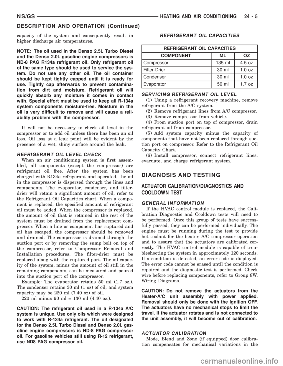
the Refrigerant Oil Capacities chart. When a compo-
nent is replaced, the specified amount of refrigerant
oil must be added. When the compressor is replaced,
the amount of oil that is retained in the rest of the
system must be drained from the replacement com-
pressor. When a line or component has ruptured and
oil has escaped, the compressor should be removed
and drained. The compressor is drained through the
suction port or by removing the sump bolt on top of
the compressor, refer to Compressor Removal and
Installation procedures. The filter-drier must be
replaced along with the ruptured part. The oil capac-
ity of the system, minus the amount of oil still in the
remaining components, can be measured and poured
into the suction port of the compressor.
Example: The evaporator retains 50 ml (1.7 oz.).
The condenser retains 30 ml (1 oz) of oil, and system
capacity may be 220 ml (7.40 oz) of oil.
220 ml minus 90 ml = 130 ml (4.40 oz.).
CAUTION: The refrigerant oil used in a R-134a A/C
system is unique. Use only oils which were designed
to work with R-134a refrigerant. The oil designated
for the Denso 2.5L Turbo Diesel and Denso 2.0L gas-
oline engine compressors is ND-8 PAG compressor
oil. For gasoline vehicles still using R-12 refrigerant,
use ND8 PAG compressor oil.
SERVICING REFRIGERANT OIL LEVEL
(1) Using a refrigerant recovery machine, remove
refrigerant from the A/C system.
(2) Remove refrigerant lines from A/C compressor.
(3) Remove compressor from vehicle.
(4) From suction port on top of compressor, drain
refrigerant oil from compressor.
(5) Add system capacity minus the capacity of
components that have not been replaced through suc-
tion port on compressor. Refer to the Refrigerant Oil
Capacity Chart.
(6) Install compressor, connect refrigerant lines,
evacuate, and charge refrigerant system.
DIAGNOSIS AND TESTING
ACTUATOR CALIBRATION/DIAGNOSTICS AND
COOLDOWN TEST
GENERAL INFORMATION
If the HVAC control module is replaced, the Cali-
bration Diagnostic and Cooldown tests will need to
be performed. Once this group of tests have success-
fully passed, they can be performed individually. The
engine must be running during the test to provide
hot coolant for the heater, A/C compressor operation
and to assure that the actuators are calibrated cor-
rectly. The HVAC control module is capable of trou-
bleshooting the system in approximately 120 seconds.
If a condition is detected, an error code is displayed.
The error code cannot be erased until the condition is
repaired and the diagnostic test is performed. Check
wire before replacing components, refer to Group 8W,
Wiring Diagrams.
CAUTION: Do not remove the actuators from the
Heater-A/C unit assembly with power applied.
Removal should only be done with the Ignition OFF.
The actuators have no mechanical stops to limit the
travel. If the actuator rotates and is not connected to
the unit assembly, it will become out of calibration.
ACTUATOR CALIBRATION
Mode, Blend and Zone (if equipped) door calibra-
tion compensates for mechanical variations in the
REFRIGERANT OIL CAPACITIES
REFRIGERANT OIL CAPACITIES
COMPONENT ML OZ
Compressor 135 ml 4.5 oz
Filter-Drier 30 ml 1.0 oz
Condenser 30 ml 1.0 oz
Evaporator 50 ml 1.7 oz
NS/GSHEATING AND AIR CONDITIONING 24 - 5
DESCRIPTION AND OPERATION (Continued)
Page 1882 of 1938
SERVICE PROCEDURES
R-134a REFRIGERANT
This vehicle uses a new type of refrigerant called
R-134a. It is a non-toxic, non-flammable, clear color-
less liquefied gas.
R-134a refrigerant is not compatible with R-12
refrigerant in an air conditioning system. Even a
small amount of R-12 in a R-134a system could cause
compressor failure, refrigerant oil to sludge and/or
poor performance.Never add any other type of
refrigerant to a system designed to use R-134a
refrigerant. System failure will occur.
The high pressure service port is located on the liq-
uid line near the strut tower. The low pressure ser-
vice port is located on the suction line near the
compressor manifold.
When servicing a system, it is required that an air
conditioning charging recovery/recycling machine be
used (Fig. 8). Contact an automotive service equip-
ment supplier for proper equipment. Refer to the
operating instructions provided with the equipment
for proper operation.
A manifold gauge set (Fig. 9) must also be used in
conjunction with the charging and/or recovery/recy-
cling device. Only use gauges that have not been
used for R-12. The service hoses on the gauge setshould have manual (turn wheel) or automatic back
flow valves at the service port connector ends. This
will prevent refrigerant R-134a from being released
into the atmosphere.
R-134a refrigerant requires a special type of com-
pressor oil. When adding oil, make sure to use the oil
that is specified on the under hood label.
Due to the different characteristics of R-134a it
requires all new service procedures.
Charge Determination Chart
Fig. 8 Refrigerant Recovery/Recycling Station
(Typical)
24 - 16 HEATING AND AIR CONDITIONINGNS/GS
DIAGNOSIS AND TESTING (Continued)