1996 CHRYSLER VOYAGER oil type
[x] Cancel search: oil typePage 1218 of 1938
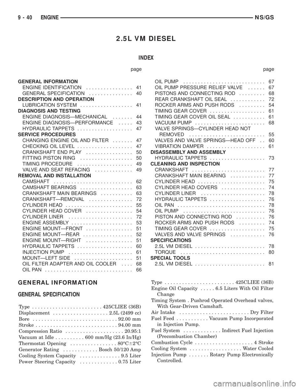
2.5L VM DIESEL
INDEX
page page
GENERAL INFORMATION
ENGINE IDENTIFICATION................ 41
GENERAL SPECIFICATION............... 40
DESCRIPTION AND OPERATION
LUBRICATION SYSTEM.................. 41
DIAGNOSIS AND TESTING
ENGINE DIAGNOSISÐMECHANICAL....... 44
ENGINE DIAGNOSISÐPERFORMANCE..... 43
HYDRAULIC TAPPETS................... 47
SERVICE PROCEDURES
CHANGING ENGINE OIL AND FILTER....... 47
CHECKING OIL LEVEL................... 47
CRANKSHAFT END PLAY................ 50
FITTING PISTON RING.................. 50
TIMING PROCEDURE................... 49
VALVE AND SEAT REFACING............. 49
REMOVAL AND INSTALLATION
CAMSHAFT........................... 62
CAMSHAFT BEARINGS.................. 63
CRANKSHAFT MAIN BEARINGS........... 63
CRANKSHAFTÐREMOVAL............... 72
CYLINDER HEAD....................... 55
CYLINDER HEAD COVER................ 54
CYLINDER LINER...................... 72
ENGINE ASSEMBLY..................... 53
ENGINE MOUNTÐFRONT................ 51
ENGINE MOUNTÐREAR................. 52
ENGINE MOUNTÐRIGHT................ 51
HYDRAULIC TAPPETS................... 60
INJECTION PUMP...................... 61
MOUNTÐLEFT SIDE.................... 51
OIL FILTER ADAPTER AND OIL COOLER.... 68
OILPAN .............................. 66OIL PUMP............................ 67
OIL PUMP PRESSURE RELIEF VALVE...... 67
PISTONS AND CONNECTING ROD......... 68
REAR CRANKSHAFT OIL SEAL............ 72
ROCKER ARMS AND PUSH RODS......... 54
TIMING GEAR COVER................... 61
TIMING GEAR COVER OIL SEAL........... 61
VACUUM PUMP........................ 68
VALVE SPRINGSÐCYLINDER HEAD NOT
REMOVED.......................... 55
VALVES AND VALVE SPRINGSÐHEAD OFF . . 60
VIBRATION DAMPER.................... 61
DISASSEMBLY AND ASSEMBLY
HYDRAULIC TAPPETS................... 73
CLEANING AND INSPECTION
CRANKSHAFT......................... 77
CRANKSHAFT MAIN BEARING............ 77
CYLINDER HEAD....................... 75
CYLINDER HEAD COVERS............... 74
CYLINDER LINER...................... 78
HYDRAULIC TAPPETS................... 76
OILPAN .............................. 78
OIL PUMP............................ 76
PISTON AND CONNECTING ROD.......... 76
ROCKER ARMS AND PUSH RODS......... 74
TIMING GEAR COVER................... 75
VALVES AND VALVE SPRINGS............ 76
SPECIFICATIONS
2.5L VM DIESEL........................ 78
TORQUE............................. 80
SPECIAL TOOLS
2.5L VM DIESEL........................ 81
GENERAL INFORMATION
GENERAL SPECIFICATION
Type ........................425CLIEE (36B)
Displacement...................2.5L (2499 cc)
Bore.............................92.00 mm
Stroke............................94.00 mm
Compression Ratio....................20.95:1
Vacuum at Idle..........600mm/Hg (23.6 In/Hg)
Thermostat Opening................80ÉC62ÉC
Generator Rating............Bosch 50/120 Amp
Cooling System Capacity..............9.5Liter
Power Steering Capacity.............0.75 LiterType ........................425CLIEE (36B)
Engine Oil Capacity.....6.5Liters With Oil Filter
Change
Timing System . Pushrod Operated Overhead valves,
With Gear-Driven Camshaft.
Air Intake........................DryFilter
Fuel Feed...........Vacuum Pump Incorporated
in Injection Pump.
Fuel System.............Indirect Fuel Injection
(Precombustion Chamber)
Combustion Cycle....................4Stroke
Cooling System..................Water Cooled
Injection Pump.......Rotary Pump Electronically
Controlled.
9 - 40 ENGINENS/GS
Page 1219 of 1938
Type ........................425CLIEE (36B)
Lubrication . Pressure Lubrication by Rotary Pump,
Full-Flow Filtration
Engine Rotation....Clockwise Viewed From Front
Cover
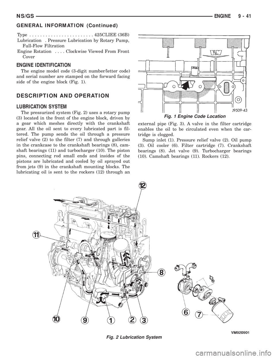
ENGINE IDENTIFICATION
The engine model code (3-digit number/letter code)
and serial number are stamped on the forward facing
side of the engine block (Fig. 1).
DESCRIPTION AND OPERATION
LUBRICATION SYSTEM
The pressurized system (Fig. 2) uses a rotary pump
(3) located in the front of the engine block, driven by
a gear which meshes directly with the crankshaft
gear. All the oil sent to every lubricated part is fil-
tered. The pump sends the oil through a pressure
relief valve (2) to the filter (7) and through galleries
in the crankcase to the crankshaft bearings (8), cam-
shaft bearings (11) and turbocharger (10). The piston
pins, connecting rod small ends and insides of the
pistons are lubricated and cooled by oil sprayed out
from jets (9) in the crankshaft mounting blocks. The
lubricating oil is sent to the rockers (12) through anexternal pipe (Fig. 3). A valve in the filter cartridge
enables the oil to be circulated even when the car-
tridge is clogged.
Sump inlet (1). Pressure relief valve (2). Oil pump
(3). Oil cooler (6). Filter cartridge (7). Crankshaft
bearings (8). Jet valve (9). Turbocharger bearings
(10). Camshaft bearings (11). Rockers (12).
Fig. 2 Lubrication System
Fig. 1 Engine Code Location
NS/GSENGINE 9 - 41
GENERAL INFORMATION (Continued)
Page 1226 of 1938
ENGINE OIL CHANGE
WARNING: NEW OR USED ENGINE OIL CAN BE
IRRITATING TO THE SKIN. AVOID PROLONGED OR
REPEATED SKIN CONTACT WITH ENGINE OIL.
CONTAMINANTS IN USED ENGINE OIL, CAUSED BY
INTERNAL COMBUSTION, CAN BE HAZARDOUS TO
YOUR HEALTH. THOROUGHLY WASH EXPOSED
SKIN WITH SOAP AND WATER. DO NOT WASH
SKIN WITH GASOLINE, DIESEL FUEL, THINNER, OR
SOLVENTS, HEALTH PROBLEMS CAN RESULT. DO
NOT POLLUTE, DISPOSE OF USED ENGINE OIL
PROPERLY. CONTACT YOUR DEALER OR GOVERN-
MENT AGENCY FOR LOCATION OF COLLECTION
CENTER IN YOUR AREA.
Run engine until achieving normal operating tem-
perature.
(1) Position the vehicle on a level surface and turn
engine off.
(2) Remove oil fill cap.
(3) Hoist vehicle. Refer to Hoisting and Jacking
Recommendations.
(4) Place a suitable drain pan under crankcase
drain.
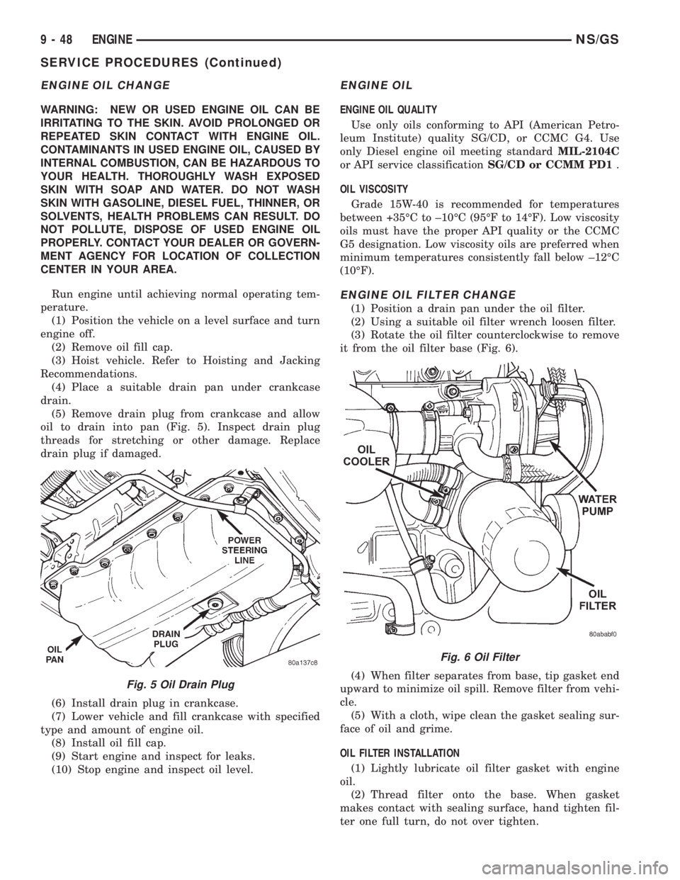
(5) Remove drain plug from crankcase and allow
oil to drain into pan (Fig. 5). Inspect drain plug
threads for stretching or other damage. Replace
drain plug if damaged.
(6) Install drain plug in crankcase.
(7) Lower vehicle and fill crankcase with specified
type and amount of engine oil.
(8) Install oil fill cap.
(9) Start engine and inspect for leaks.
(10) Stop engine and inspect oil level.
ENGINE OIL
ENGINE OIL QUALITY
Use only oils conforming to API (American Petro-
leum Institute) quality SG/CD, or CCMC G4. Use
only Diesel engine oil meeting standardMIL-2104C
or API service classificationSG/CD or CCMM PD1.
OIL VISCOSITY
Grade 15W-40 is recommended for temperatures
between +35ÉC to ±10ÉC (95ÉF to 14ÉF). Low viscosity
oils must have the proper API quality or the CCMC
G5 designation. Low viscosity oils are preferred when
minimum temperatures consistently fall below ±12ÉC
(10ÉF).
ENGINE OIL FILTER CHANGE
(1) Position a drain pan under the oil filter.
(2) Using a suitable oil filter wrench loosen filter.
(3) Rotate the oil filter counterclockwise to remove
it from the oil filter base (Fig. 6).
(4) When filter separates from base, tip gasket end
upward to minimize oil spill. Remove filter from vehi-
cle.
(5) With a cloth, wipe clean the gasket sealing sur-
face of oil and grime.
OIL FILTER INSTALLATION
(1) Lightly lubricate oil filter gasket with engine
oil.
(2) Thread filter onto the base. When gasket
makes contact with sealing surface, hand tighten fil-
ter one full turn, do not over tighten.
Fig. 5 Oil Drain Plug
Fig. 6 Oil Filter
9 - 48 ENGINENS/GS
SERVICE PROCEDURES (Continued)
Page 1248 of 1938
PISTON RINGÐREMOVAL
(1) Identification (ID) mark on face of upper and
intermediate piston rings must point toward piston
crown.
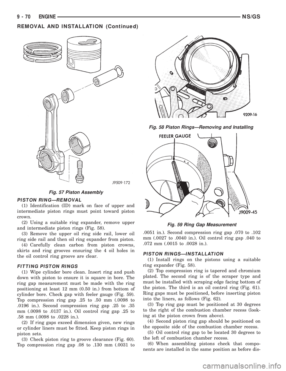
(2) Using a suitable ring expander, remove upper
and intermediate piston rings (Fig. 58).
(3) Remove the upper oil ring side rail, lower oil
ring side rail and then oil ring expander from piston.
(4) Carefully clean carbon from piston crowns,
skirts and ring grooves ensuring the 4 oil holes in
the oil control ring groove are clear.
FITTING PISTON RINGS
(1) Wipe cylinder bore clean. Insert ring and push
down with piston to ensure it is square in bore. The
ring gap measurement must be made with the ring
positioning at least 12 mm (0.50 in.) from bottom of
cylinder bore. Check gap with feeler gauge (Fig. 59).
Top compression ring gap .25 to .50 mm (.0098 to
.0196 in.). Second compression ring gap .25 to .35
mm (.0098 to .0137 in.). Oil control ring gap .25 to
.58 mm (.0098 to .0228 in.).
(2) If ring gaps exceed dimension given, new rings
or cylinder liners must be fitted. Keep piston rings in
piston sets.
(3) Check piston ring to groove clearance (Fig. 60).
Top compression ring gap .08 to .130 mm (.0031 to.0051 in.). Second compression ring gap .070 to .102
mm (.0027 to .0040 in.). Oil control ring gap .040 to
.072 mm (.0015 to .0028 in.).
PISTON RINGSÐINSTALLATION
(1) Install rings on the pistons using a suitable
ring expander (Fig. 58).
(2) Top compression ring is tapered and chromium
plated. The second ring is of the scraper type and
must be installed with scraping edge facing bottom of
the piston. The third is an oil control ring (Fig. 61).
Ring gaps must be positioned, before inserting piston
into the liners, as follows (Fig. 62).
(3) Top ring gap must be positioned at 30 degrees
to the right of the combustion chamber recess (look-
ing at the piston crown from above).
(4) Second piston ring gap should be positioned on
the opposite side of the combustion chamber recess.
(5) Oil control ring gap to be located 30 degrees to
the left of combustion chamber recess.
(6) When assembling pistons check that compo-
nents are installed in the same position as before dis-
Fig. 57 Piston Assembly
Fig. 58 Piston RingsÐRemoving and Installing
Fig. 59 Ring Gap Measurement
9 - 70 ENGINENS/GS
REMOVAL AND INSTALLATION (Continued)
Page 1256 of 1938
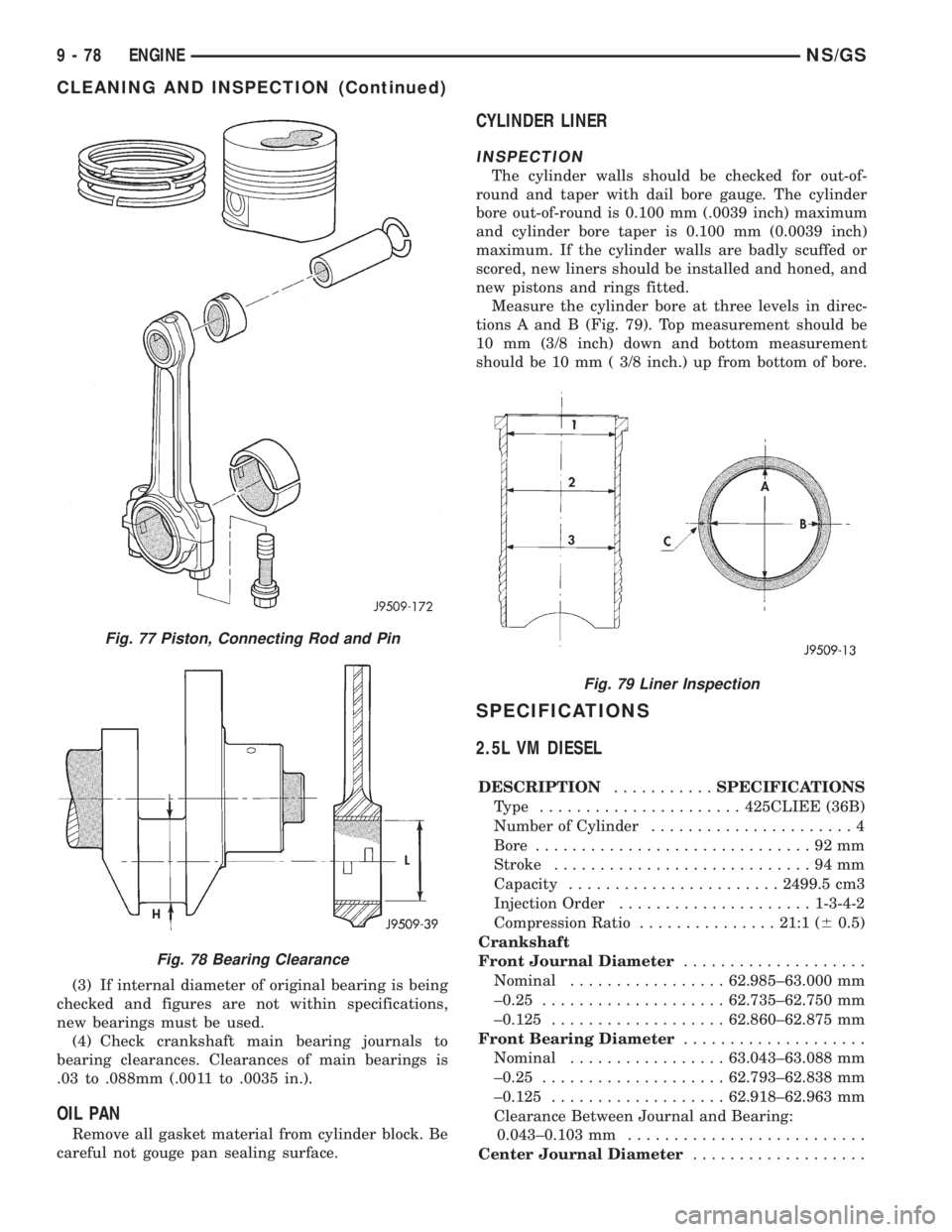
(3) If internal diameter of original bearing is being
checked and figures are not within specifications,
new bearings must be used.
(4) Check crankshaft main bearing journals to
bearing clearances. Clearances of main bearings is
.03 to .088mm (.0011 to .0035 in.).
OIL PAN
Remove all gasket material from cylinder block. Be
careful not gouge pan sealing surface.
CYLINDER LINER
INSPECTION
The cylinder walls should be checked for out-of-
round and taper with dail bore gauge. The cylinder
bore out-of-round is 0.100 mm (.0039 inch) maximum
and cylinder bore taper is 0.100 mm (0.0039 inch)
maximum. If the cylinder walls are badly scuffed or
scored, new liners should be installed and honed, and
new pistons and rings fitted.
Measure the cylinder bore at three levels in direc-
tions A and B (Fig. 79). Top measurement should be
10 mm (3/8 inch) down and bottom measurement
should be 10 mm ( 3/8 inch.) up from bottom of bore.
SPECIFICATIONS
2.5L VM DIESEL
DESCRIPTION...........SPECIFICATIONS
Type ......................425CLIEE (36B)
Number of Cylinder......................4
Bore..............................92mm
Stroke............................94mm
Capacity.......................2499.5 cm3
Injection Order.....................1-3-4-2
Compression Ratio...............21:1 (60.5)
Crankshaft
Front Journal Diameter....................
Nominal.................62.985±63.000 mm
±0.25....................62.735±62.750 mm
±0.125...................62.860±62.875 mm
Front Bearing Diameter....................
Nominal.................63.043±63.088 mm
±0.25....................62.793±62.838 mm
±0.125...................62.918±62.963 mm
Clearance Between Journal and Bearing:
0.043±0.103 mm..........................
Center Journal Diameter...................
Fig. 77 Piston, Connecting Rod and Pin
Fig. 78 Bearing Clearance
Fig. 79 Liner Inspection
9 - 78 ENGINENS/GS
CLEANING AND INSPECTION (Continued)
Page 1257 of 1938
DESCRIPTION...........SPECIFICATIONS
Nominal.................63.005±63.020 mm
±0.25....................62.755±62.770 mm
±0.125...................62.880±62.895 mm
Center Bearing Diameter...................
Nominal.................63.050±63.093 mm
±0.25....................62.800±62.843 mm
±0.125...................62.925±62.968 mm
Clearance Between Journal and Bearing:
0.030±0.088 mm..........................
Rear Journal Diameter.....................
Nominal.................79.980±80.000 mm
±0.25....................79.730±79.750 mm
±0.125...................79.855±79.875 mm
Rear Bearing Diameter.....................
Nominal.................80.045±80.070 mm
±0.25....................79.795±79.820 mm
±0.125...................79.920±79.945 mm
Clearance Between Journal and Bearing:
0.045±0.090 mm (Wear Limit: 0.200 mm).......
Connecting Rod Journal....................
Nominal.................53.940±53.955 mm
±0.25....................53.690±53.705 mm
±0.125...................53.815±53.830 mm
Connecting Rod Bearing....................
Nominal.................53.977±54.016 mm
±0.25....................53.727±53.766 mm
±0.125...................53.852±53.891 mm
Clearance Between Journal and Bearing:
0.022±0.076 mm (Wear Limit: 0.200 mm).......
Crankshaft End Play
End Play.....................0.08±0.21 mm
Adjustment.................Thrust Washers
Thrust Washers Available........2.31±2.36 mm
Thrust Washers Available........2.41±2.46 mm
Thrust Washers Available........2.51±2.56 mm
Main Bearing Carriers
Front....................67.025±67.050 mm
Center...................66.670±66.690 mm
Rear....................85.985±86.005 mm
Liners
Internal Diameter..........92.000±92.010 mm
Protrusion....................0.01±0.06 mm
Adjustment.........................Shims
Available Shims:...................0.15 mm
Available Shims:...................0.17 mm
Available Shims:...................0.20 mm
Available Shims:...................0.23 mm
Available Shims:...................0.25 mm
Cylinder Head
Minimum Thickness..........89.95±90.05 mm
Gasket.............................Steel
Gasket thickness:.......1.4260.1 mm 0 Holes
Gasket thickness:.......1.6260.1 mm 1 HolesDESCRIPTION...........SPECIFICATIONS
Gasket thickness:.......1.5260.1 mm 2 Holes
End Plates
Height.....................89.02±90.00 mm
Connecting Rods
Weight (Without the crank
bearing)..................1129±1195 grams
Small End Bearing Internal Diameter
Minimum.......................30.035 mm
Maximum......................30.050 mm
Crankshaft Bearings Standard Internal
Diameter.................53.997±54.016 mm
Pistons
Skirt Diameter............91.935±91.945 mm
(Measured at approximately 15 mm above the
bottom of the skirt)
Piston Clearance.............0.055±0.075 mm
Top of Piston to Cylinder Head....0.80±0.89 mm
Piston Protrusion.....0.53±0.62 mm Fit Gasket
(1.42), 0 Holes
Piston Protrusion.....0.73±0.82 mm Fit Gasket
(1.62), 1 Hole
Piston Protrusion.....0.63±0.72 mm Fit Gasket
(1.52), 2 Holes
Piston Pins
Type .........................Full Floating
Pin Diameter..............29.990±29.996 mm
Clearance..................0.004±0.014 mm
Piston Rings (Clearance in Groove)
Top .......................0.080±0.130 mm
Second.....................0.070±0.102 mm
Oil Control.................0.040±0.072 mm
Piston Rings (Fitted Gap)
Top .........................0.25±0.50 mm
Second......................0.20±0.35 mm
Oil Control...................0.25±0.58 mm
Camshaft
Journal Diameter Front.....53.460±53.480 mm
Bearing Clearance.............0.06±0.13 mm
Journal Diameter Center....53.460±53.480 mm
Bearing Clearance.............0.06±0.13 mm
Journal Diameter Rear......53.460±53.480 mm
Bearing Clearance.............0.06±0.13 mm
Tappets
Outside Diameter..........22.195±22.212 mm
Rocker Gear
Shaft Diameter.............21.979±22.00 mm
Bushing internal diameter . . . 22.020±22.041 mm
Assembly Clearance..........0.020±0.062 mm
Valves (Intake)
Opens........................26ÉB.T.D.C.
Closes........................58ÉA.B.D.C.
Valves (Exhaust)
Opens........................64ÉB.B.D.C.
Closes........................38ÉA.T.D.C.
NS/GSENGINE 9 - 79
SPECIFICATIONS (Continued)
Page 1306 of 1938
(9) Momentarily touch the other end of this
jumper wire to the negative terminal of the battery
for no more than 4 seconds.
(10) Place a rag or towel below the fuel line at the
quick connect to the rail.
(11) Disconnect the quick connect fitting to the
rail. Refer to Quick-Connect Fittings in this section.
(12) Return the fuel pump relay to the PDC.
(13) One or more Diagnostic Trouble Codes (DTC's)
may have been stored in the PCM memory due to the
fuel pump relay removal. The DRB scan tool must be
used to erase a DTC. Refer to group 25, On-Board
Diagnostics.
HOSES AND CLAMPS
Inspect all hose connections (clamps and quick con-
nect fittings) for completeness and leaks. Replace
cracked, scuffed, or swelled hoses. Replace hoses that
rub against other vehicle components or show sign of
wear.
Fuel injected vehicles use specially constructed
hoses. When replacing hoses, only use hoses marked
EFM/EFI.
When installing hoses, ensure that they are routed
away from contact with other vehicle components
that could rub against them and cause failure. Avoid
contact with clamps or other components that cause
abrasions or scuffing. Ensure that rubber hoses are
properly routed and avoid heat sources.
The hose clamps have rolled edges to prevent the
clamp from cutting into the hose. Only use clamps
that are original equipment or equivalent. Other
types of clamps may cut into the hoses and cause
high pressure fuel leaks. Tighten hose clamps to 1
N´m (10 in. lbs.) torque.
QUICK-CONNECT FITTINGS
REMOVAL
When disconnecting a quick-connect fitting, the
retainer will remain on the fuel tube nipple.
WARNING: RELEASE FUEL SYSTEM PRESSURE
BEFORE DISCONNECTING A QUICK-CONNECT FIT-
TINGS. REFER TO THE FUEL PRESSURE RELEASE
PROCEDURE.
(1) Disconnect negative cable from battery.
(2) Perform Fuel Pressure Release Procedure.
Refer to the Fuel Pressure Release Procedure in this
section.
(3) Squeeze retainer tabs together and pull fuel
tube/quick-connect fitting assembly off of fuel tube
nipple. The retainer will remain on fuel tube.
INSTALLATION
CAUTION: Never install a quick-connect fitting
without the retainer being either on the fuel tube or
already in the quick-connect fitting. In either case,
ensure the retainer locks securely into the quick-
connect fitting by firmly pulling on fuel tube and fit-
ting to ensure it is secured.
(1) Using a clean lint free cloth, clean the fuel tube
nipple and retainer.
(2) Prior to connecting the fitting to the fuel tube,
coat the fuel tube nipple with clean 30 weight engine
oil.
(3) Push the quick-connect fitting over the fuel
tube until theretainer seats and a click is heard.
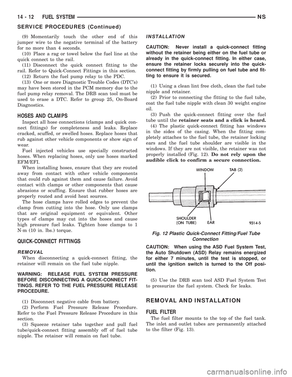
(4) The plastic quick-connect fitting has windows
in the sides of the casing. When the fitting com-
pletely attaches to the fuel tube, the retainer locking
ears and the fuel tube shoulder are visible in the
windows. If they are not visible, the retainer was not
properly installed (Fig. 12).Do not rely upon the
audible click to confirm a secure connection.
CAUTION: When using the ASD Fuel System Test,
the Auto Shutdown (ASD) Relay remains energized
for either 7 minutes, until the test is stopped, or
until the ignition switch is turned to the Off posi-
tion.
(5) Use the DRB scan tool ASD Fuel System Test
to pressurize the fuel system. Check for leaks.
REMOVAL AND INSTALLATION
FUEL FILTER
The fuel filter mounts to the top of the fuel tank.
The inlet and outlet tubes are permanently attached
to the filter (Fig. 13).
Fig. 12 Plastic Quick-Connect Fitting/Fuel Tube
Connection
14 - 12 FUEL SYSTEMNS
SERVICE PROCEDURES (Continued)
Page 1427 of 1938
STEERING
CONTENTS
page page
GENERAL INFORMATION................... 1
POWER STEERING GEAR.................. 26POWER STEERING PUMP.................. 9
STEERING COLUMN...................... 36
GENERAL INFORMATION
INDEX
page page
GENERAL INFORMATION
STEERING SYSTEM AND COMPONENT
DESCRIPTION......................... 1DIAGNOSIS AND TESTING
STEERING SYSTEM DIAGNOSIS CHARTS..... 2
GENERAL INFORMATION
STEERING SYSTEM AND COMPONENT
DESCRIPTION
The power steering system consists of these four
major components. Power Steering Pump, Power
Steering Gear, Pressure Hose, and Return Line.
Turning of the steering wheel is converted into linear
travel through the meshing of the helical pinion
teeth with the rack teeth. Power assist steering is
provided by an open center, rotary type control valve.
It is used to direct oil from the pump to either side of
the integral steering rack piston.
Road feel is controlled by the diameter of a torsion
bar which initially steers the vehicle. As requiredsteering effort increases, as in a turn, the torsion bar
twists, causing relative rotary motion between the
rotary valve body and the valve spool. This move-
ment directs oil behind the integral rack piston,
which, in turn, builds up hydraulic pressure and
assists in the turning effort.
Drive tangs on the power steering gear pinion
shaft, mate loosely with the shaft of the steering
gear. This is to allow manual steering control to be
maintained, if the drive belt on the power steering
pump should break. However, under these conditions,
steering effort will significantly increase.
NSSTEERING 19 - 1