1996 CHRYSLER VOYAGER oil type
[x] Cancel search: oil typePage 1139 of 1938
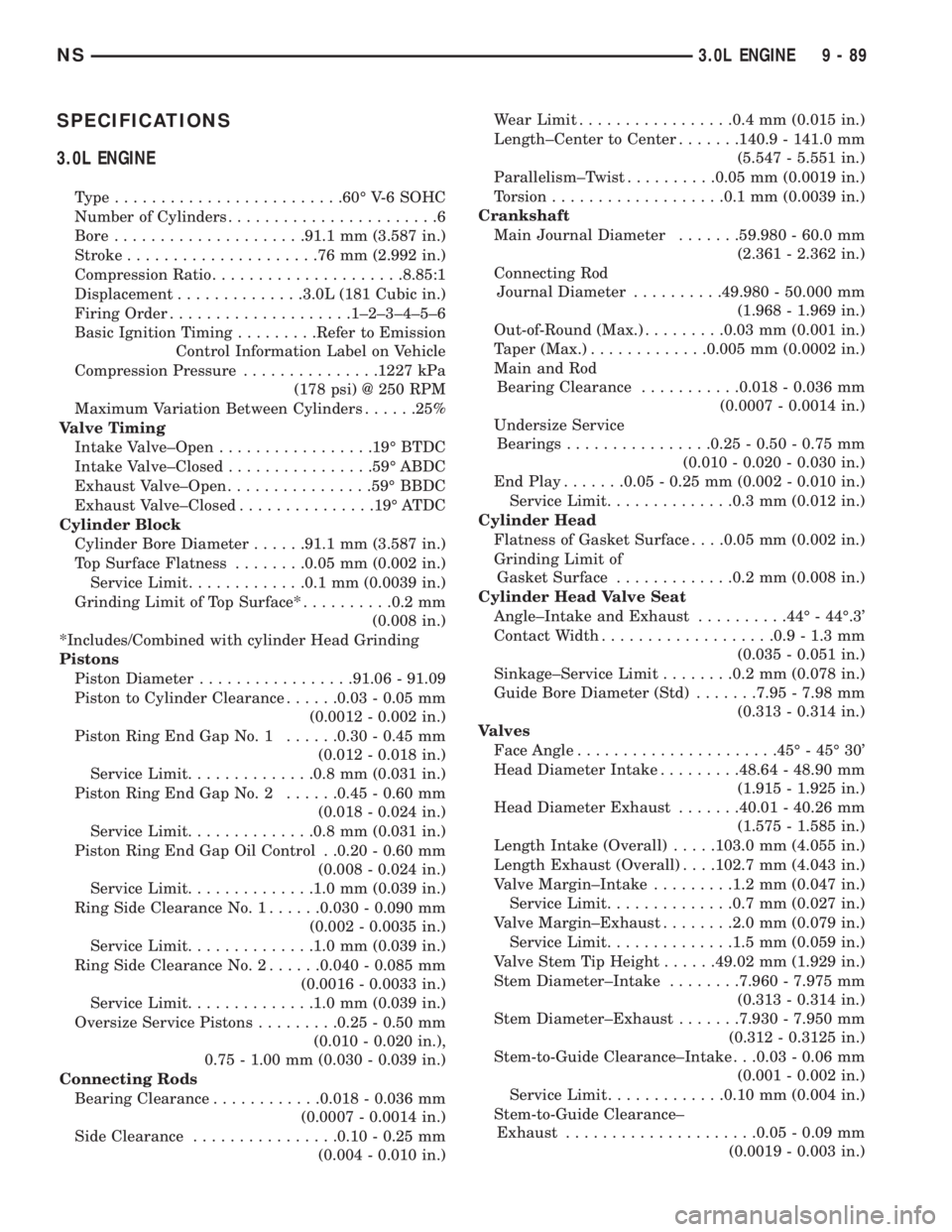
SPECIFICATIONS
3.0L ENGINE
Type.........................60É V-6 SOHC
Number of Cylinders.......................6
Bore.....................91.1 mm (3.587 in.)
Stroke.....................76mm(2.992 in.)
Compression Ratio.....................8.85:1
Displacement..............3.0L (181 Cubic in.)
Firing Order....................1±2±3±4±5±6
Basic Ignition Timing.........Refer to Emission
Control Information Label on Vehicle
Compression Pressure...............1227 kPa
(178 psi) @ 250 RPM
Maximum Variation Between Cylinders......25%
Valve Timing
Intake Valve±Open.................19É BTDC
Intake Valve±Closed................59É ABDC
Exhaust Valve±Open................59É BBDC
Exhaust Valve±Closed...............19É ATDC
Cylinder Block
Cylinder Bore Diameter......91.1 mm (3.587 in.)
Top Surface Flatness........0.05 mm (0.002 in.)
Service Limit.............0.1 mm (0.0039 in.)
Grinding Limit of Top Surface*..........0.2 mm
(0.008 in.)
*Includes/Combined with cylinder Head Grinding
Pistons
Piston Diameter.................91.06 - 91.09
Piston to Cylinder Clearance......0.03 - 0.05 mm
(0.0012 - 0.002 in.)
Piston Ring End Gap No. 1......0.30 - 0.45 mm
(0.012 - 0.018 in.)
Service Limit..............0.8 mm (0.031 in.)
Piston Ring End Gap No. 2......0.45 - 0.60 mm
(0.018 - 0.024 in.)
Service Limit..............0.8 mm (0.031 in.)
Piston Ring End Gap Oil Control . .0.20 - 0.60 mm
(0.008 - 0.024 in.)
Service Limit..............1.0 mm (0.039 in.)
Ring Side Clearance No. 1......0.030 - 0.090 mm
(0.002 - 0.0035 in.)
Service Limit..............1.0 mm (0.039 in.)
Ring Side Clearance No. 2......0.040 - 0.085 mm
(0.0016 - 0.0033 in.)
Service Limit..............1.0 mm (0.039 in.)
Oversize Service Pistons.........0.25 - 0.50 mm
(0.010 - 0.020 in.),
0.75 - 1.00 mm (0.030 - 0.039 in.)
Connecting Rods
Bearing Clearance............0.018 - 0.036 mm
(0.0007 - 0.0014 in.)
Side Clearance................0.10 - 0.25 mm
(0.004 - 0.010 in.)Wear Limit.................0.4 mm (0.015 in.)
Length±Center to Center.......140.9 - 141.0 mm
(5.547 - 5.551 in.)
Parallelism±Twist..........0.05 mm (0.0019 in.)
Torsion...................0.1 mm (0.0039 in.)
Crankshaft
Main Journal Diameter.......59.980 - 60.0 mm
(2.361 - 2.362 in.)
Connecting Rod
Journal Diameter..........49.980 - 50.000 mm
(1.968 - 1.969 in.)
Out-of-Round (Max.).........0.03 mm (0.001 in.)
Taper (Max.).............0.005 mm (0.0002 in.)
Main and Rod
Bearing Clearance...........0.018 - 0.036 mm
(0.0007 - 0.0014 in.)
Undersize Service
Bearings................0.25 - 0.50 - 0.75 mm
(0.010 - 0.020 - 0.030 in.)
End Play.......0.05 - 0.25 mm (0.002 - 0.010 in.)
Service Limit..............0.3 mm (0.012 in.)
Cylinder Head
Flatness of Gasket Surface. . . .0.05 mm (0.002 in.)
Grinding Limit of
Gasket Surface.............0.2 mm (0.008 in.)
Cylinder Head Valve Seat
Angle±Intake and Exhaust..........44É - 44É.3'
Contact Width...................0.9 - 1.3 mm
(0.035 - 0.051 in.)
Sinkage±Service Limit........0.2 mm (0.078 in.)
Guide Bore Diameter (Std).......7.95 - 7.98 mm
(0.313 - 0.314 in.)
Valves
Face Angle......................45É - 45É 30'
Head Diameter Intake.........48.64 - 48.90 mm
(1.915 - 1.925 in.)
Head Diameter Exhaust.......40.01 - 40.26 mm
(1.575 - 1.585 in.)
Length Intake (Overall).....103.0 mm (4.055 in.)
Length Exhaust (Overall). . . .102.7 mm (4.043 in.)
Valve Margin±Intake.........1.2 mm (0.047 in.)
Service Limit..............0.7 mm (0.027 in.)
Valve Margin±Exhaust........2.0 mm (0.079 in.)
Service Limit..............1.5 mm (0.059 in.)
Valve Stem Tip Height......49.02 mm (1.929 in.)
Stem Diameter±Intake........7.960 - 7.975 mm
(0.313 - 0.314 in.)
Stem Diameter±Exhaust.......7.930 - 7.950 mm
(0.312 - 0.3125 in.)
Stem-to-Guide Clearance±Intake . . .0.03 - 0.06 mm
(0.001 - 0.002 in.)
Service Limit.............0.10 mm (0.004 in.)
Stem-to-Guide Clearance±
Exhaust.....................0.05 - 0.09 mm
(0.0019 - 0.003 in.)
NS3.0L ENGINE 9 - 89
Page 1143 of 1938
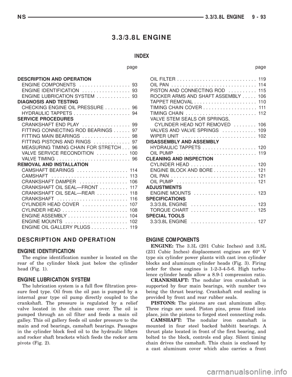
3.3/3.8L ENGINE
INDEX
page page
DESCRIPTION AND OPERATION
ENGINE COMPONENTS.................. 93
ENGINE IDENTIFICATION................. 93
ENGINE LUBRICATION SYSTEM............ 93
DIAGNOSIS AND TESTING
CHECKING ENGINE OIL PRESSURE......... 96
HYDRAULIC TAPPETS.................... 94
SERVICE PROCEDURES
CRANKSHAFT END PLAY................. 99
FITTING CONNECTING ROD BEARINGS...... 97
FITTING MAIN BEARINGS................. 98
FITTING PISTONS AND RINGS............. 97
MEASURING TIMING CHAIN FOR STRETCH . . . 96
VALVE SERVICE RECONDITION........... 100
VALVE TIMING.......................... 96
REMOVAL AND INSTALLATION
CAMSHAFT BEARINGS.................. 114
CAMSHAFT........................... 113
CRANKSHAFT DAMPER................. 106
CRANKSHAFT OIL SEALÐFRONT.......... 117
CRANKSHAFT OIL SEALÐREAR........... 118
CRANKSHAFT......................... 116
CYLINDER HEAD COVER................ 107
CYLINDER HEAD....................... 108
ENGINE ASSEMBLY..................... 104
ENGINE MOUNTS...................... 102
ENGINE OIL GALLERY PLUGS............. 119OILFILTER ............................ 119
OILPAN .............................. 114
PISTON AND CONNECTING ROD.......... 115
ROCKER ARMS AND SHAFT ASSEMBLY..... 106
TAPPET REMOVAL...................... 110
TIMING CHAIN COVER................... 111
TIMING CHAIN......................... 112
VALVE STEM SEALS OR SPRINGS,
CYLINDER HEAD NOT REMOVED........ 106
VALVES AND VALVE SPRINGS............ 109
WIPER UNIT.......................... 102
DISASSEMBLY AND ASSEMBLY
HYDRAULIC TAPPETS................... 120
OIL PUMP............................ 119
CLEANING AND INSPECTION
CYLINDER HEAD....................... 120
ENGINE BLOCK AND BORE............... 121
OILPAN .............................. 121
OIL PUMP............................ 121
ADJUSTMENTS
ENGINE MOUNTS...................... 123
SPECIFICATIONS
3.3/3.8L ENGINE....................... 123
TORQUE CHART....................... 125
SPECIAL TOOLS
3.3/3.8L ENGINE....................... 127
DESCRIPTION AND OPERATION
ENGINE IDENTIFICATION
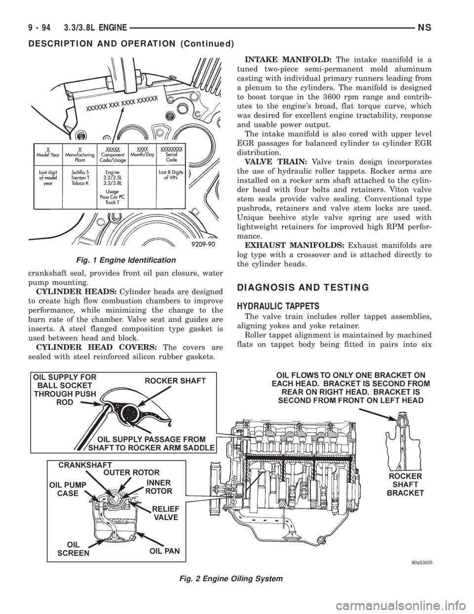
The engine identification number is located on the
rear of the cylinder block just below the cylinder
head (Fig. 1).
ENGINE LUBRICATION SYSTEM
The lubrication system is a full flow filtration pres-
sure feed type. Oil from the oil pan is pumped by a
internal gear type oil pump directly coupled to the
crankshaft. The pressure is regulated by a relief
valve located in the chain case cover. The oil is
pumped through an oil filter and feeds a main oil
galley. This oil gallery feeds oil under pressure to the
main and rod bearings, camshaft bearings. Passages
in the cylinder block feed oil to the hydraulic lifters
and rocker shaft brackets which feeds the rocker arm
pivots (Fig. 2).
ENGINE COMPONENTS
ENGINE:The 3.3L (201 Cubic Inches) and 3.8L
(231 Cubic Inches) displacement engines are 60É V
type six cylinder power plants with cast iron cylinder
blocks and aluminum cylinder heads (Fig. 3). Firing
order for these engines is 1-2-3-4-5-6. High turbu-
lence cylinder heads allow a 8.9-1 compression ratio.
CRANKSHAFT:The nodular iron crankshaft is
supported by four main bearings, with number two
being the thrust bearing. Crankshaft end sealing is
provided by front and rear rubber seals.
PISTONS:The pistons are cast aluminum alloy.
Three rings are used. Piston pins, press fitted into
place, join the pistons to forged steel connecting rods.
CAMSHAFT:The nodular iron camshaft is
mounted in four steel backed babbitt bearings. A
thrust plate located in front of the first bearing, and
bolted to the block, controls end play. Silent timing
chain drives the camshaft. This chain is enclosed by
a cast aluminum cover which also carries a front
NS3.3/3.8L ENGINE 9 - 93
Page 1144 of 1938
crankshaft seal, provides front oil pan closure, water
pump mounting.
CYLINDER HEADS:Cylinder heads are designed
to create high flow combustion chambers to improve
performance, while minimizing the change to the
burn rate of the chamber. Valve seat and guides are
inserts. A steel flanged composition type gasket is
used between head and block.
CYLINDER HEAD COVERS:The covers are
sealed with steel reinforced silicon rubber gaskets.INTAKE MANIFOLD:The intake manifold is a
tuned two-piece semi-permanent mold aluminum
casting with individual primary runners leading from
a plenum to the cylinders. The manifold is designed
to boost torque in the 3600 rpm range and contrib-
utes to the engine's broad, flat torque curve, which
was desired for excellent engine tractability, response
and usable power output.
The intake manifold is also cored with upper level
EGR passages for balanced cylinder to cylinder EGR
distribution.
VALVE TRAIN:Valve train design incorporates
the use of hydraulic roller tappets. Rocker arms are
installed on a rocker arm shaft attached to the cylin-
der head with four bolts and retainers. Viton valve
stem seals provide valve sealing. Conventional type
pushrods, retainers and valve stem locks are used.
Unique beehive style valve spring are used with
lightweight retainers for improved high RPM perfor-
mance.
EXHAUST MANIFOLDS:Exhaust manifolds are
log type with a crossover and is attached directly to
the cylinder heads.
DIAGNOSIS AND TESTING
HYDRAULIC TAPPETS
The valve train includes roller tappet assemblies,
aligning yokes and yoke retainer.
Roller tappet alignment is maintained by machined
flats on tappet body being fitted in pairs into six
Fig. 2 Engine Oiling System
Fig. 1 Engine Identification
9 - 94 3.3/3.8L ENGINENS
DESCRIPTION AND OPERATION (Continued)
Page 1157 of 1938
(4) Remove upper intake manifold. Refer to Group
11, Exhaust System and Intake Manifolds for proce-
dure.
(5) Remove cylinder head covers and spark plugs.
(6) Remove electrical connector from ignition coils.
(7) Using suitable socket and flex handle at crank-
shaft pulley retaining screw, turn engine so the num-
ber 1 piston is at Top Dead Center on the
compression stroke.
(8) Remove rocker arms with rocker shaft and
install a dummy shaft. The rocker arms should not
be disturbed and left on shaft.
(9) With air hose attached to spark plug adapter
installed in number 1 spark plug hole, apply 90 to
100 psi air pressure (620.5 to 689 kPa). This is to
hold valves in place while servicing components.
(10) Using Tool C-4682 or equivalent, compress
valve spring and remove retainer valve locks and
valve spring.
(11) The intake valve stem seals should be pushed
firmly and squarely over the valve guide using the
valve stem as guide.Do Not Forceseal against top
of guide. When installing the valve retainer locks,
compress the springonly enoughto install the
locks.
CAUTION: Do not pinch seal between retainer and
top of valve guide.
(12) Follow the same procedure on the remaining 5
cylinders using the firing sequence 1-2-3-4-5-6.Make
sure piston in cylinder is at TDC on the valve
spring that is being covered.
(13) Remove spark plug adapter tool.
(14) Remove dummy shaft and install rocker shaft
assembly and tighten screws to 28 N´m (250 in. lbs.).
(15) Install cylinder head covers tighten screws to
14 N´m (120 in. lbs.) and electrical connector to igni-
tion coils.
(16) Install Intake Manifold. Refer to Group 11,
Exhaust System and Intake Manifold for procedure.
(17) Connect negative cable to battery.
CYLINDER HEAD COVER
REMOVAL
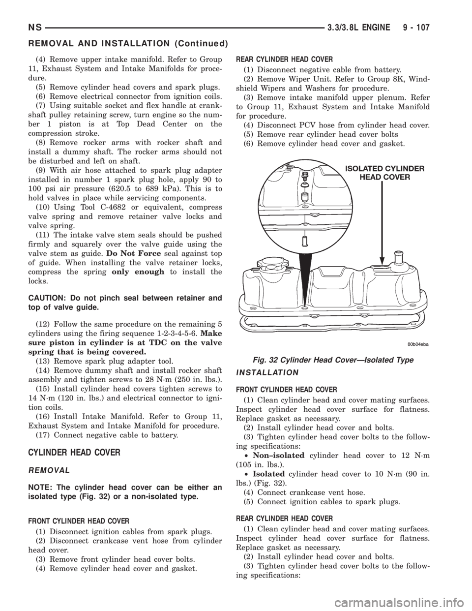
NOTE: The cylinder head cover can be either an
isolated type (Fig. 32) or a non-isolated type.
FRONT CYLINDER HEAD COVER
(1) Disconnect ignition cables from spark plugs.
(2) Disconnect crankcase vent hose from cylinder
head cover.
(3) Remove front cylinder head cover bolts.
(4) Remove cylinder head cover and gasket.REAR CYLINDER HEAD COVER
(1) Disconnect negative cable from battery.
(2) Remove Wiper Unit. Refer to Group 8K, Wind-
shield Wipers and Washers for procedure.
(3) Remove intake manifold upper plenum. Refer
to Group 11, Exhaust System and Intake Manifold
for procedure.
(4) Disconnect PCV hose from cylinder head cover.
(5) Remove rear cylinder head cover bolts
(6) Remove cylinder head cover and gasket.
INSTALLATION
FRONT CYLINDER HEAD COVER
(1) Clean cylinder head and cover mating surfaces.
Inspect cylinder head cover surface for flatness.
Replace gasket as necessary.
(2) Install cylinder head cover and bolts.
(3) Tighten cylinder head cover bolts to the follow-
ing specifications:
²Non±isolatedcylinder head cover to 12 N´m
(105 in. lbs.).
²Isolatedcylinder head cover to 10 N´m (90 in.
lbs.) (Fig. 32).
(4) Connect crankcase vent hose.
(5) Connect ignition cables to spark plugs.
REAR CYLINDER HEAD COVER
(1) Clean cylinder head and cover mating surfaces.
Inspect cylinder head cover surface for flatness.
Replace gasket as necessary.
(2) Install cylinder head cover and bolts.
(3) Tighten cylinder head cover bolts to the follow-
ing specifications:
Fig. 32 Cylinder Head CoverÐIsolated Type
NS3.3/3.8L ENGINE 9 - 107
REMOVAL AND INSTALLATION (Continued)
Page 1174 of 1938
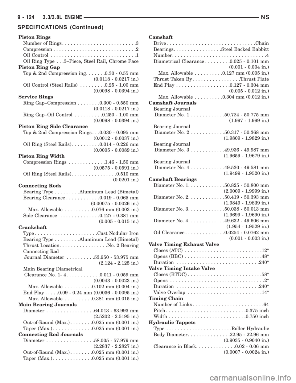
Piston Rings
Number of Rings..........................3
Compression.............................2
Oil Control..............................1
Oil Ring Type . . .3±Piece, Steel Rail, Chrome Face
Piston Ring Gap
Top & 2nd Compression ing.......0.30 - 0.55 mm
(0.0118 - 0.0217 in.)
Oil Control (Steel Rails).........0.25 - 1.00 mm
(0.0098 - 0.0394 in.)
Service Rings
Ring Gap±Compression........0.300 - 0.550 mm
(0.0118 - 0.0217 in.)
Ring Gap±Oil Control..........0.250 - 1.00 mm
(0.0098 - 0.0394 in.)
Piston Ring Side Clearance
Top & 2nd Compression Rings . . .0.030 - 0.095 mm
(0.0012 - 0.0037 in.)
Oil Ring (Steel Rails)..........0.014 - 0.226 mm
(0.0005 - 0.0089 in.)
Piston Ring Width
Compression Rings.............1.46 - 1.50 mm
(0.0575 - 0.0591 in.)
Oil Ring (Steel Rails)................0.510 mm
(0.0201 in.)
Connecting Rods
Bearing Type.........Aluminum Lead (Bimetal)
Bearing Clearance............0.019 - 0.065 mm
(0.00075 - 0.0026 in.)
Max. Allowable..........0.076 mm (0.003 in.)
Side Clearance..............0.127 - 0.381 mm
(0.005 - 0.015 in.)
Crankshaft
Type......................Cast Nodular Iron
Bearing Type.........Aluminum Lead (Bimetal)
Thrust Location.................No. 2 Bearing
Connecting Rod
Journal Diameter..........53.950 - 53.975 mm
(2.124 - 2.125 in.)
Main Bearing Diametrical
Clearance No. 1- 4............0.011 - 0.059 mm
(0.0043 - 0.0023 in.)
Max. Allowable..........0.102 mm (0.004 in.)
End Play.....0.09 - 0.24 mm (0.0036 - 0.0095 in.)
Max. Allowable..........0.381 mm (0.015 in.)
Main Bearing Journals
Diameter.................64.013 - 63.993 mm
(2.5202 - 2.5195 in.)
Out-of-Round (Max.)........0.025 mm (0.001 in.)
Taper (Max.)..............0.025 mm (0.001 in.)
Connecting Rod Journals
Diameter.................58.005 - 57.979 mm
(2.2837 - 2.2827 in.)
Out-of-Round (Max.)........0.025 mm (0.001 in.)
Taper (Max.)..............0.025 mm (0.001 in.)Camshaft
Drive...............................Chain
Bearings.................Steel Backed Babbitt
Number.................................4
Diametrical Clearance.........0.025 - 0.101 mm
(0.001 - 0.004 in.)
Max. Allowable..........0.127 mm (0.005 in.)
Thrust Taken By.................Thrust Plate
End Play...................0.127 - 0.304 mm
(0.005 - 0.012 in.)
Max. Allowable..........0.304 mm (0.012 in.)
Camshaft Journals
Bearing Journal
Diameter No. 1............50.724 - 50.775 mm
(1.997 - 1.999 in.)
Bearing Journal
Diameter No. 2............50.317 - 50.368 mm
(1.9809 - 1.9829 in.)
Bearing Journal
Diameter No. 3............49.936 - 49.987 mm
(1.9659 - 1.9679 in.)
Bearing Journal
Diameter No. 4............49.530 - 49.581 mm
(1.9499 - 1.9520 in.)
Camshaft Bearings
Diameter No. 1.............50.825 - 50.800 mm
(2.0009 - 1.9999 in.)
Diameter No. 2.............50.419 - 50.393 mm
(1.9849 - 1.9839 in.)
Diameter No. 3.............50.038 - 50.013 mm
(1.9699 - 1.9690 in.)
Diameter No. 4.............49.632 - 49.606 mm
(1.954 - 1.9529 in.)
Oil Clearance..............0.0254 - 0.0762 mm
(0.001 - 0.003 in.)
Valve Timing Exhaust Valve
Closes (ATC)...........................12É
Opens (BBC)...........................48É
Duration.............................240É
Valve Timing Intake Valve
Closes (BTDC)..........................58É
Opens.................................2É
Duration.............................240É
Valve Overlap..........................14É
Timing Chain
Number of Links.........................64
Pitch............................0.375 inch
Width...........................0.750 inch
Hydraulic Tappets
Type .......................Roller Hydraulic
Body Diameter...............22.95 - 22.96 mm
(0.9035 - 0.9040 in.)
Clearance in Block..............0.02 - 0.06 mm
(0.0007 - 0.0024 in.)
9 - 124 3.3/3.8L ENGINENS
SPECIFICATIONS (Continued)
Page 1175 of 1938
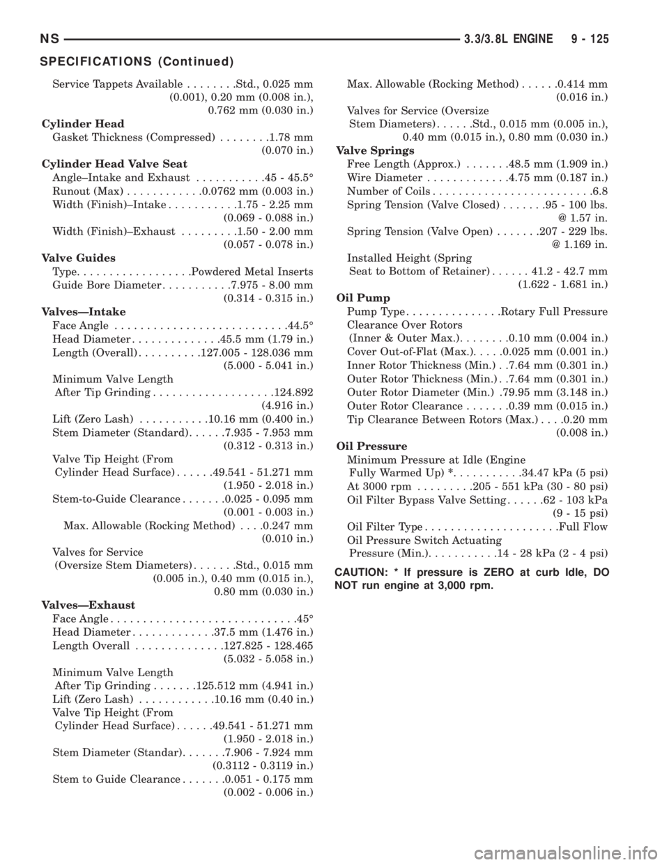
Service Tappets Available........Std., 0.025 mm
(0.001), 0.20 mm (0.008 in.),
0.762 mm (0.030 in.)
Cylinder Head
Gasket Thickness (Compressed)........1.78 mm
(0.070 in.)
Cylinder Head Valve Seat
Angle±Intake and Exhaust...........45-45.5É
Runout (Max)............0.0762 mm (0.003 in.)
Width (Finish)±Intake...........1.75 - 2.25 mm
(0.069 - 0.088 in.)
Width (Finish)±Exhaust.........1.50 - 2.00 mm
(0.057 - 0.078 in.)
Valve Guides
Type..................Powdered Metal Inserts
Guide Bore Diameter...........7.975 - 8.00 mm
(0.314 - 0.315 in.)
ValvesÐIntake
Face Angle...........................44.5É
Head Diameter..............45.5 mm (1.79 in.)
Length (Overall)..........127.005 - 128.036 mm
(5.000 - 5.041 in.)
Minimum Valve Length
After Tip Grinding...................124.892
(4.916 in.)
Lift (Zero Lash)...........10.16 mm (0.400 in.)
Stem Diameter (Standard)......7.935 - 7.953 mm
(0.312 - 0.313 in.)
Valve Tip Height (From
Cylinder Head Surface)......49.541 - 51.271 mm
(1.950 - 2.018 in.)
Stem-to-Guide Clearance.......0.025 - 0.095 mm
(0.001 - 0.003 in.)
Max. Allowable (Rocking Method). . . .0.247 mm
(0.010 in.)
Valves for Service
(Oversize Stem Diameters).......Std., 0.015 mm
(0.005 in.), 0.40 mm (0.015 in.),
0.80 mm (0.030 in.)
ValvesÐExhaust
Face Angle.............................45É
Head Diameter.............37.5 mm (1.476 in.)
Length Overall..............127.825 - 128.465
(5.032 - 5.058 in.)
Minimum Valve Length
After Tip Grinding.......125.512 mm (4.941 in.)
Lift (Zero Lash)............10.16 mm (0.40 in.)
Valve Tip Height (From
Cylinder Head Surface)......49.541 - 51.271 mm
(1.950 - 2.018 in.)
Stem Diameter (Standar).......7.906 - 7.924 mm
(0.3112 - 0.3119 in.)
Stem to Guide Clearance.......0.051 - 0.175 mm
(0.002 - 0.006 in.)Max. Allowable (Rocking Method)......0.414 mm
(0.016 in.)
Valves for Service (Oversize
Stem Diameters)......Std., 0.015 mm (0.005 in.),
0.40 mm (0.015 in.), 0.80 mm (0.030 in.)
Valve Springs
Free Length (Approx.).......48.5 mm (1.909 in.)
Wire Diameter.............4.75 mm (0.187 in.)
Number of Coils.........................6.8
Spring Tension (Valve Closed).......95-100lbs.
@ 1.57 in.
Spring Tension (Valve Open).......207 - 229 lbs.
@ 1.169 in.
Installed Height (Spring
Seat to Bottom of Retainer)......41.2 - 42.7 mm
(1.622 - 1.681 in.)
Oil Pump
Pump Type...............Rotary Full Pressure
Clearance Over Rotors
(Inner & Outer Max.)........0.10 mm (0.004 in.)
Cover Out-of-Flat (Max.).....0.025 mm (0.001 in.)
Inner Rotor Thickness (Min.) . .7.64 mm (0.301 in.)
Outer Rotor Thickness (Min.) . .7.64 mm (0.301 in.)
Outer Rotor Diameter (Min.) .79.95 mm (3.148 in.)
Outer Rotor Clearance.......0.39 mm (0.015 in.)
Tip Clearance Between Rotors (Max.). . . .0.20 mm
(0.008 in.)
Oil Pressure
Minimum Pressure at Idle (Engine
Fully Warmed Up)*...........34.47 kPa (5 psi)
At 3000 rpm.........205 - 551 kPa (30 - 80 psi)
Oil Filter Bypass Valve Setting......62-103kPa
(9 - 15 psi)
Oil Filter Type.....................Full Flow
Oil Pressure Switch Actuating
Pressure (Min.)...........14-28kPa(2 - 4 psi)
CAUTION: * If pressure is ZERO at curb Idle, DO
NOT run engine at 3,000 rpm.
NS3.3/3.8L ENGINE 9 - 125
SPECIFICATIONS (Continued)
Page 1180 of 1938
GENERAL SPECIFICATION
Type .............In-Line OHV, DOHC & SOHC
Bore.....................87.5mm (3.445 Inch)
Stroke...................83.0mm (3.268 inch)
Compression Ratio....DOHC - 9.6:1 SOHC - 9.8:1
Displacement.........2.0Liters (122 Cubic Inch)
Firing Order........................1,3,4,2
Compression Pressure...........1172-1551 kPa
(170 - 225 psi)
Maximum Variation Between Cylinders......25%
Lubrication . . . Pressure Feed - Full Flow Filtration
(Crankshaft Driven Pump)
Engine Oil Capacity . . Refer to Group 0, Lubrication
and Maintenance
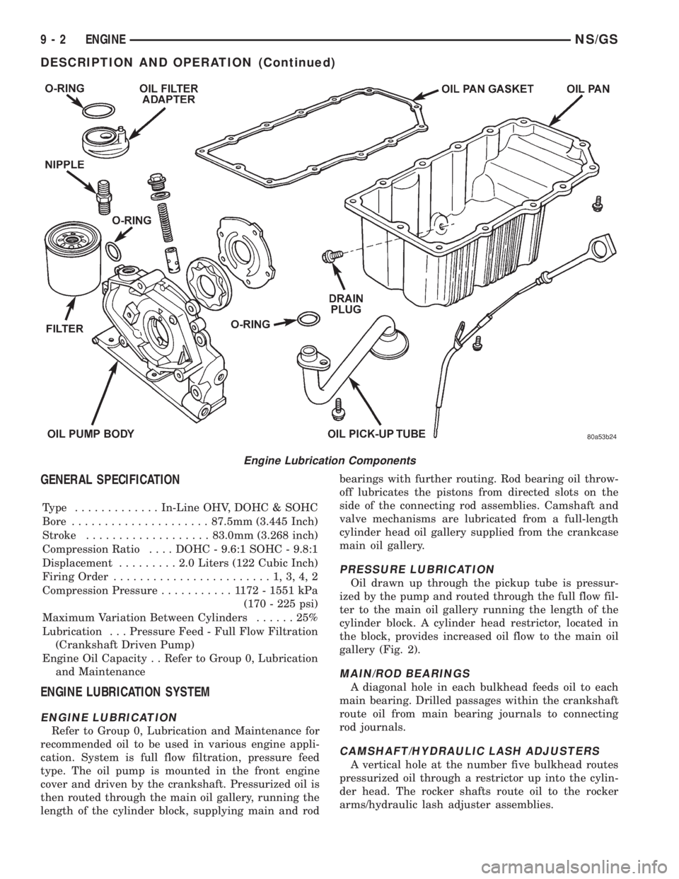
ENGINE LUBRICATION SYSTEM
ENGINE LUBRICATION
Refer to Group 0, Lubrication and Maintenance for
recommended oil to be used in various engine appli-
cation. System is full flow filtration, pressure feed
type. The oil pump is mounted in the front engine
cover and driven by the crankshaft. Pressurized oil is
then routed through the main oil gallery, running the
length of the cylinder block, supplying main and rodbearings with further routing. Rod bearing oil throw-
off lubricates the pistons from directed slots on the
side of the connecting rod assemblies. Camshaft and
valve mechanisms are lubricated from a full-length
cylinder head oil gallery supplied from the crankcase
main oil gallery.
PRESSURE LUBRICATION
Oil drawn up through the pickup tube is pressur-
ized by the pump and routed through the full flow fil-
ter to the main oil gallery running the length of the
cylinder block. A cylinder head restrictor, located in
the block, provides increased oil flow to the main oil
gallery (Fig. 2).
MAIN/ROD BEARINGS
A diagonal hole in each bulkhead feeds oil to each
main bearing. Drilled passages within the crankshaft
route oil from main bearing journals to connecting
rod journals.
CAMSHAFT/HYDRAULIC LASH ADJUSTERS
A vertical hole at the number five bulkhead routes
pressurized oil through a restrictor up into the cylin-
der head. The rocker shafts route oil to the rocker
arms/hydraulic lash adjuster assemblies.
Engine Lubrication Components
9 - 2 ENGINENS/GS
DESCRIPTION AND OPERATION (Continued)
Page 1182 of 1938
(4) If oil pressure is 0 at idle. Shut off engine,
check for pressure relief valve stuck open, a clogged
oil pick-up screen or a damaged oil pick-up tube
O-ring.
SERVICE PROCEDURES
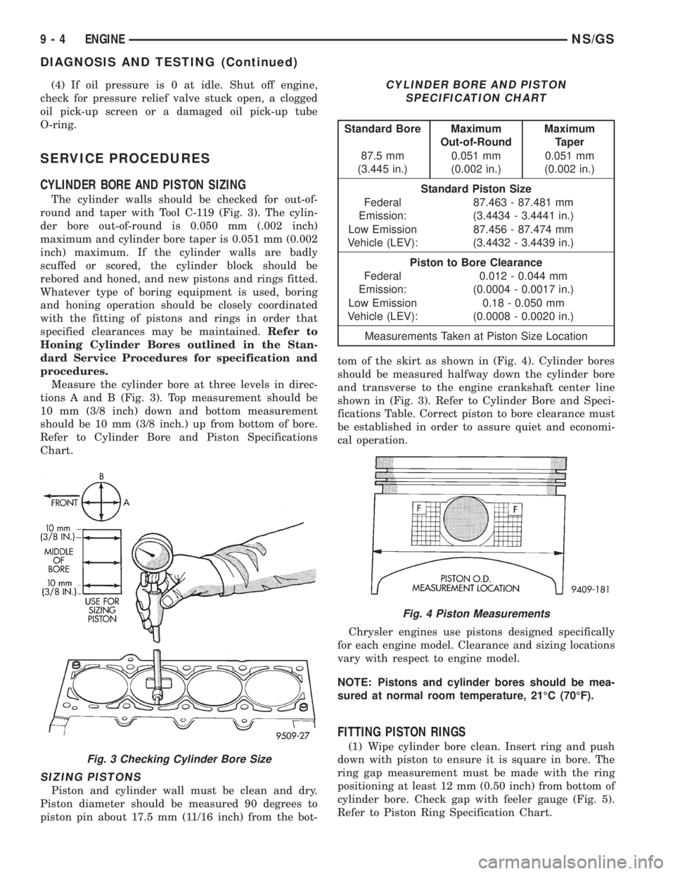
CYLINDER BORE AND PISTON SIZING
The cylinder walls should be checked for out-of-
round and taper with Tool C-119 (Fig. 3). The cylin-
der bore out-of-round is 0.050 mm (.002 inch)
maximum and cylinder bore taper is 0.051 mm (0.002
inch) maximum. If the cylinder walls are badly
scuffed or scored, the cylinder block should be
rebored and honed, and new pistons and rings fitted.
Whatever type of boring equipment is used, boring
and honing operation should be closely coordinated
with the fitting of pistons and rings in order that
specified clearances may be maintained.Refer to
Honing Cylinder Bores outlined in the Stan-
dard Service Procedures for specification and
procedures.
Measure the cylinder bore at three levels in direc-
tions A and B (Fig. 3). Top measurement should be
10 mm (3/8 inch) down and bottom measurement
should be 10 mm (3/8 inch.) up from bottom of bore.
Refer to Cylinder Bore and Piston Specifications
Chart.
SIZING PISTONS
Piston and cylinder wall must be clean and dry.
Piston diameter should be measured 90 degrees to
piston pin about 17.5 mm (11/16 inch) from the bot-tom of the skirt as shown in (Fig. 4). Cylinder bores
should be measured halfway down the cylinder bore
and transverse to the engine crankshaft center line
shown in (Fig. 3). Refer to Cylinder Bore and Speci-
fications Table. Correct piston to bore clearance must
be established in order to assure quiet and economi-
cal operation.
Chrysler engines use pistons designed specifically
for each engine model. Clearance and sizing locations
vary with respect to engine model.
NOTE: Pistons and cylinder bores should be mea-
sured at normal room temperature, 21ÉC (70ÉF).
FITTING PISTON RINGS
(1) Wipe cylinder bore clean. Insert ring and push
down with piston to ensure it is square in bore. The
ring gap measurement must be made with the ring
positioning at least 12 mm (0.50 inch) from bottom of
cylinder bore. Check gap with feeler gauge (Fig. 5).
Refer to Piston Ring Specification Chart.
Fig. 3 Checking Cylinder Bore Size
CYLINDER BORE AND PISTON
SPECIFICATION CHART
Standard Bore Maximum
Out-of-RoundMaximum
Taper
87.5 mm
(3.445 in.)0.051 mm
(0.002 in.)0.051 mm
(0.002 in.)
Standard Piston Size
Federal
Emission:87.463 - 87.481 mm
(3.4434 - 3.4441 in.)
Low Emission
Vehicle (LEV):87.456 - 87.474 mm
(3.4432 - 3.4439 in.)
Piston to Bore Clearance
Federal
Emission:0.012 - 0.044 mm
(0.0004 - 0.0017 in.)
Low Emission
Vehicle (LEV):0.18 - 0.050 mm
(0.0008 - 0.0020 in.)
Measurements Taken at Piston Size Location
Fig. 4 Piston Measurements
9 - 4 ENGINENS/GS
DIAGNOSIS AND TESTING (Continued)