1996 CHRYSLER VOYAGER oil type
[x] Cancel search: oil typePage 310 of 1938

plugs.Ash encrusted spark plugs can be cleaned
and reused.
HIGH SPEED MISS
When replacing spark plugs because of a high
speed miss condition;wide open throttle opera-
tion should be avoided for approximately 80 km
(50 miles) after installation of new plugs.This
will allow deposit shifting in the combustion chamber
to take place gradually and avoid plug destroying
splash fouling shortly after the plug change.
ELECTRODE GAP BRIDGING
Loose deposits in the combustion chamber can
cause electrode gap bridging. The deposits accumu-
late on the spark plugs during continuous stop-
and-go driving. When the engine is suddenly
subjected to a high torque load, the deposits partially
liquefy and bridge the gap between the electrodes
(Fig. 25). This short circuits the electrodes.Spark
plugs with electrode gap bridging can be
cleaned and reused.
SCAVENGER DEPOSITS
Fuel scavenger deposits may be either white or yel-
low (Fig. 26). They may appear to be harmful, but
are a normal condition caused by chemical additives
in certain fuels. These additives are designed to
change the chemical nature of deposits and decrease
spark plug misfire tendencies. Notice that accumula-
tion on the ground electrode and shell area may be
heavy but the deposits are easily removed.Spark
plugs with scavenger deposits can be consid-
ered normal in condition, cleaned and reused.
CHIPPED ELECTRODE INSULATOR
A chipped electrode insulator usually results from
bending the center electrode while adjusting the
spark plug electrode gap. Under certain conditions,
severe detonation also can separate the insulator
from the center electrode (Fig. 27).Spark plugs
with chipped electrode insulators must be
replaced.
PREIGNITION DAMAGE
Excessive combustion chamber temperature can
cause preignition damage. First, the center electrode
dissolves and the ground electrode dissolves some-
what later (Fig. 28). Insulators appear relatively
deposit free. Determine if the spark plugs are the
correct type, as specified on the VECI label, or if
other operating conditions are causing engine over-
heating.
SPARK PLUG OVERHEATING
Overheating is indicated by a white or gray center
electrode insulator that also appears blistered (Fig.
Fig. 24 Oil or Ash Encrusted
Fig. 25 Electrode Gap Bridging
Fig. 26 Scavenger Deposits
8D - 12 IGNITION SYSTEMNS
DIAGNOSIS AND TESTING (Continued)
Page 327 of 1938

CAUTION: Never coat the inside of spark plug
boots with silicone grease. Some types of silicone
grease can damage the ignition cable conductor.
SPARK PLUG CABLES #3 AND #5
REMOVAL
(1) Remove the resonator.
(2) Grasp the spark plug boot/heat shield as close
as possible to the spark plug.Twist the boot
slightly to break its seal with the plug and pull
straight back. Do not use pliers, pull on the
ignition cable, or pull the spark plug boot at an
angle.This could damage the spark plug insulator,
terminal, or the cable insulation. Wipe spark plug
insulator clean with a dry cloth before installation.
(3) Remove the cable from the retaining bracket.
Make sure that they are also detached from the rear
retaining clip mounted on the rear of the intake
manifold.
INSTALLATION
(1) When installing the spark plug cables, make
sure the coil and spark plug insulator and terminals
are fully seated. Aclick sound should be heard or
terminal engagement is felt when the terminals
are properly attached.
(2) Install the cable into the retaining bracket.
Make sure that they are also attached to the rear
retaining clip mounted on the rear of the intake
manifold.
(3) Install the resonator.
SPARK PLUG CABLE #1
REMOVAL
(1) Remove the accessory drive belt, refer to Group
7, Cooling.
(2) Remove the four bolts from the upper half of
the generator bracket.
(3) Push the Generator rearward.
(4) Grasp the spark plug boot/shield assembly as
close as possible to the spark plug.Twist the boot
slightly to break its seal with the plug and pull
straight back. Do not use pliers, pull on the
ignition cable, or pull the spark plug boot at an
angle.This could damage the spark plug insulator,
terminal, or the cable insulation. Wipe spark plug
insulator clean with a dry cloth before installation.
(5) Remove the cable from the retaining bracket.
INSTALLATION
(1) When installing the spark plug cables, make
sure the coil and spark plug insulator and terminals
are fully seated. Aclick sound should be heard orterminal engagement is felt when the terminals
are properly attached.
(2) Rotate Generator back into place.
(3) Install upper Generator bracket with the four
bolts.
(4) Install the accessory drive belt, refer to Group
7, Cooling.
SPARK PLUG SERVICEÐ3.3/3.8L ENGINES
WARNING: The ignition cables should not be
removed while the engine is hot. This could cause
server injury/burns and can cause damage to the
ignition cables.
Use extreme care when removing and installing
the spark plug cables.
The spark plug boot heat shield needs to be
installed correctly on the boot before being installed
on the engine (Fig. 1). If it is not installed correctly
engine misfire would occur.
Do not use pliers to pull the boot/heat shield
assembly from the spark plugs. This will damage the
shield assembly.
SPARK PLUG #3 AND #5
REMOVAL
(1) Remove the resonator.
(2) Remove intake strut to cylinder head bolt at
cylinder head.
(3) Loosen bolt for intake strut at intake.
(4) Swing strut away.
(5) Grasp the spark plug boot/shield assembly as
close as possible to the spark plug.Twist the boot/
shield assembly slightly to break the seal with
the plug and pull straight out. Do not use pli-
ers, pull on the ignition cable, or pull the spark
plug boot at an angle.This could damage the
spark plug insulator, terminal, heat shield or the
insulation. Wipe spark plug insulator clean with a
dry cloth before installation.
(6) Remove spark plug
INSTALLATION
(1) Install spark plug and tighten to 28 N´m (20 ft.
lbs.).
(2) When installing the spark plug cables, make
sure spark plug insulator and terminals are fully
seated. Aclick sound should be heard or felt
when the terminals are properly attached.
(3) Install the cable into the retaining bracket.
Make sure that they are also attached to the rear
retaining clip mounted on the rear of the intake
manifold.
(4) Swing strut back into place.
NSIGNITION SYSTEM 8D - 29
REMOVAL AND INSTALLATION (Continued)
Page 1051 of 1938
ENGINE
CONTENTS
page page
2.4L ENGINE............................ 14
3.0L ENGINE............................ 61
3.3/3.8L ENGINE........................ 93ENGINE DIAGNOSIS....................... 7
STANDARD SERVICE PROCEDURES.......... 1
STANDARD SERVICE PROCEDURES
INDEX
page page
GENERAL INFORMATION
CRANKSHAFT SPROCKET BOLT ACCESS
PLUG................................ 2
ENGINE CORE PLUGS.................... 2
ENGINE OIL SERVICE..................... 5
ENGINE OIL............................. 5
ENGINE PERFORMANCE.................. 2FORM-IN-PLACE GASKETS................. 1
HONING CYLINDER BORES................ 3
HYDROSTATIC LOCKED ENGINE............ 5
MEASURING MAIN BEARING AND
CONNECTING ROD BEARING
CLEARANCES......................... 3
REPAIR OF DAMAGED OR WORN THREADS . . . 4
GENERAL INFORMATION
FORM-IN-PLACE GASKETS
There are numerous places where form-in-place
gaskets are used on the engine. Care must be taken
when applying form-in-place gaskets.Do not use
form-in-place gasket material unless specified.
Bead size, continuity, and location are of great impor-
tance. Too thin a bead can result in leakage while too
much can result in spill-over, a continuous bead of
the proper width is essential to obtain a leak-free
joint.
Two types of form-in-place gasket materials are
used in the engine.MopartSilicone Rubber Adhe-
sive Sealant andMopartGasket Maker, (anaerobic)
each have different properties and cannot be used
interchangeably.
CAUTION: Silicone sealer and anaerobic sealers
each will inhibit the cure of the other and care
should be taken to keep usages separated as much
as possible.
MOPARTSILICONE RUBBER ADHESIVE
SEALANT
MopartSilicone Rubber Adhesive Sealant or
equivalent, normally black in color, is available in
three ounce tubes. Moisture in the air causes the
MopartSilicone Rubber Adhesive Sealant material
to cure. This material is normally used on flexible
metal flanges. It has a shelf life of one year and will
not properly cure if over age. Always inspect the
package for the expiration date before use.
MOPARTGASKET MAKER
MopartGasket Maker is an anaerobic type gasket
material normally red in color. The material cures in
the absence of air when squeezed between two metal-
lic surfaces. It will not cure if left in the uncovered
tube. It is normally red in color. The anaerobic mate-
rial is for use between two machined surfaces. Do not
use on flexible metal flanges.
MOPARTTORQUE CURE GASKET MAKER
MopartTorque Cure Gasket Maker is a unique
anaerobic type gasket material to be usedONLY
between the bedplate and engine block. The material
cures in the absence of air when torqued between
two metallic surfaces. It will not cure if left in the
uncovered tube. This anaerobic material is specially
NSENGINE 9 - 1
Page 1056 of 1938
API SERVICE GRADE CERTIFIED
Use an engine oil that is API Service Grade Certi-
fied. MOPARtprovides engine oils that conforms to
this service grade.
SAE VISCOSITY
An SAE viscosity grade is used to specify the vis-
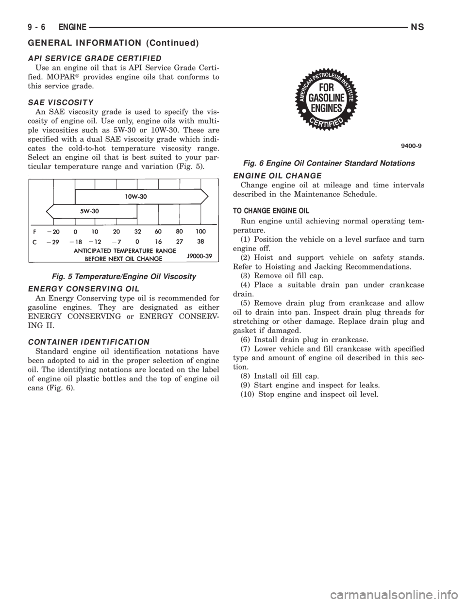
cosity of engine oil. Use only, engine oils with multi-
ple viscosities such as 5W-30 or 10W-30. These are
specified with a dual SAE viscosity grade which indi-
cates the cold-to-hot temperature viscosity range.
Select an engine oil that is best suited to your par-
ticular temperature range and variation (Fig. 5).
ENERGY CONSERVING OIL
An Energy Conserving type oil is recommended for
gasoline engines. They are designated as either
ENERGY CONSERVING or ENERGY CONSERV-
ING II.
CONTAINER IDENTIFICATION
Standard engine oil identification notations have
been adopted to aid in the proper selection of engine
oil. The identifying notations are located on the label
of engine oil plastic bottles and the top of engine oil
cans (Fig. 6).
ENGINE OIL CHANGE
Change engine oil at mileage and time intervals
described in the Maintenance Schedule.
TO CHANGE ENGINE OIL
Run engine until achieving normal operating tem-
perature.
(1) Position the vehicle on a level surface and turn
engine off.
(2) Hoist and support vehicle on safety stands.
Refer to Hoisting and Jacking Recommendations.
(3) Remove oil fill cap.
(4) Place a suitable drain pan under crankcase
drain.
(5) Remove drain plug from crankcase and allow
oil to drain into pan. Inspect drain plug threads for
stretching or other damage. Replace drain plug and
gasket if damaged.
(6) Install drain plug in crankcase.
(7) Lower vehicle and fill crankcase with specified
type and amount of engine oil described in this sec-
tion.
(8) Install oil fill cap.
(9) Start engine and inspect for leaks.
(10) Stop engine and inspect oil level.
Fig. 5 Temperature/Engine Oil Viscosity
Fig. 6 Engine Oil Container Standard Notations
9 - 6 ENGINENS
GENERAL INFORMATION (Continued)
Page 1066 of 1938
sealing and a chrome plated taper faced intermediate
ring for additional cylinder pressure control. There
are also standard oil control rings.
CYLINDER HEAD:Features a Dual Over Head
Camshaft (DOHC) 4 valves per cylinder cross flow
design. The valves are arranged in two inline banks,
with the ports of the bank of two intake valves per
cylinder facing toward the radiator side of engine
and ports of the bank of two exhaust valves per cyl-
inder facing toward the dash panel. Incorporates
powder metal valve guides and seats. Integral oil gal-
leys within the cylinder head supplies oil to the
hydraulic lash adjusters, camshaft and valve mecha-
nisms.
CAMSHAFTS:The nodular iron camshafts have
six bearing journals and 2 cam lobes per cylinder.
Flanges at the rear journals control camshaft end
play. Provision for cam position sensor is located on
the intake camshaft at the rear of cylinder head. A
hydrodynamic oil seal is used for oil control at the
front of the camshaft.
VALVES:4 valves per cylinder are actuated by
roller cam followers which pivot on stationary
hydraulic lash adjusters. All valves have 6 mm diam-
eter chrome plated valve stems. The valve sizes are
34.8 mm (1.370 inch.) diameter intake valves and
30.5 mm (1.20 inch.) diameter exhaust valves. Viton
rubber valve stem seals are integral with the spring
seats. Valve springs, spring retainers, and locks are
conventional.
INTAKE MANIFOLD:The intake manifold is a
two piece aluminum casting, attached to the cylinder
head with ten screws. This long branch fan design
enhances low and midspeed torque, while minimizing
undesirable inlet noise.
EXHAUST MANIFOLD:The exhaust manifold is
made of cast iron for strength and high tempera-
tures.
ENGINE LUBRICATION:Refer to Group 0
Lubrication and Maintenance for recommended oil to
be used in various engine application. System is full
flow filtration, pressure feed type. The oil pump is
mounted in the front engine cover and driven by the
crankshaft. Pressurized oil is then routed through
the main oil gallery, running the length of the cylin-
der block, supplying main and rod bearings with fur-
ther routing. Pistons are lubricated from rod bearing
throw off and lubricating slots on the connecting rod
assemblies. Camshaft and valve mechanisms are
lubricated from a full length cylinder head oil gallery
supplied from the crankcase main oil gallery.DIAGNOSIS AND TESTING
CHECKING ENGINE OIL PRESSURE
(1) Remove oil pressure sending unit and install
gauge assembly C-3292.
(2) Run engine until thermostat opens.
CAUTION: If oil pressure is 0 at idle, Do Not Run
engine at 3000 RPM
(3) Oil Pressure:Curb Idle25 kPa (4 psi) mini-
mum3000 RPM170/550 kPa (25/80 psi).
(4) If oil pressure is 0 at idle. Shut off engine,
check for pressure relief valve stuck open or a
clogged oil pickup screen.
SERVICE PROCEDURES
FITTING PISTONS
Piston and cylinder wall must be clean and dry.
Piston diameter should be measured 90 degrees to
piston pin about 14 mm (9/16 inch.) from the bottom
of the skirt as shown in (Fig. 3). Cylinder bores
should be measured halfway down the cylinder bore
and transverse to the engine crankshaft center line
shown in (Fig. 2). Refer to Cylinder Bore and Piston
Specification Chart.
Correct piston to bore clearance must be estab-
lished in order to assure quiet and economical oper-
ation.
Chrysler engines use pistons designed specifically
for each engine model. Clearance and sizing locations
vary with respect to engine model.
NOTE: Pistons and cylinder bores should be mea-
sured at normal room temperature, 70ÉF (21ÉC).
FITTING PISTON RINGS
(1) Wipe cylinder bore clean. Insert ring and push
down with piston to ensure it is square in bore. The
ring gap measurement must be made with the ring
positioning at least 12 mm (0.50 inch) from bottom of
cylinder bore. Check gap with feeler gauge (Fig. 4).
Refer to specification in Piston Ring Specification
Chart.
(2) Check piston ring to groove side clearance (Fig.
5). Refer to specification in Piston Ring Specification
Chart.
9 - 16 2.4L ENGINENS
DESCRIPTION AND OPERATION (Continued)
Page 1105 of 1938
SPECIFICATIONS
2.4L ENGINE
Type....................In-Line OHV, DOHC
Number of Cylinder.......................4
Bore.....................87.5 mm (3.445 in.)
Stroke....................101 mm (3.976 in.)
Compression Ratio......................9.4:1
Displacement.......2.4 Liters (148 Cubic Inches)
Firing Order.......................1,3,4,2
Compression Pressure...........1172-1551 kPa
(170-225 psi)
Maximum Variation Between Cylinder......25%
Lubrication. . . .Pressure Feed-Full Flow Filtration
(Direct Crankshaft Driven Pump)
Cylinder Block
Cylinder Bore Diameter. . . .87.4924 - 87.5076 mm
(3.4446 - 3.4452 in.)
Out-of-Round (Max.)........0.051 mm (0.002 in.)
Taper (Max.)..............0.051 mm (0.002 in.)
Pistons
Clearance at 14 mm (9/16 in.)
From Bottom of Skirt.........0.024 - 0.057 mm
(0.0009 - 0.0022 in.)
Weight......................332 - 346 grams
(11.85 - 12.20 oz.)
Top Land Clearance
(Diametrical)................0.614 - 0.664 mm
(0.024 - 0.026 in.)
Piston Length.............60.30 mm (2.374 in.)
Piston Ring Groove Depth
No.1........4.640 - 4.784 mm (0.182 - 0.188 in.)
No.2........4.575 - 4.719 mm (0.180 - 0.185 in.)
No.3........4.097 - 4.236 mm (0.161 - 0.166 in.)
Piston Pins
Clearance in Piston...........0.005 - 0.018 mm
In Rod (Interference)..........0.018 - 0.043 mm
(0.0007 - 0.0017 in.)
Diameter.................21.998 - 22.003 mm
(0.8660 - 0.8662 in.)
End Play.............................None
Length.....................72.75 - 73.25 mm
(2.864 - 2.883 in.)
Piston Ring Gap
Top Compression Ring...........0.25 - 0.51 mm
(0.0098 - 0.020 in.)
2nd Compression Ring...........0.23 - 0.48 mm
(0.009 - 0.018 in.)
Oil Control (Steel Rails).........0.25 - 0.64 mm
(0.0098 - 0.025 in.)
Piston Ring Side Clearance
Top and Second
Compression Rings...........0.030 - 0.080 mm
(0.0011 - 0.0031 in.)Oil Ring (Pack)..............0.012 - 0.178 mm
(0.0004 - 0.0070 in.)
Piston Ring Width
Compression Rings.............1.47 - 1.50 mm
(0.057 - 0.059 in.)
Oil Ring (Pack)................2.72 - 2.88 mm
(0.107 - 0.1133 in.)
Connecting Rod
Bearing Clearance............0.025 - 0.071 mm
(0.0009 - 0.0027 in.)
Piston Pin Bore Diameter......20.96 - 20.98 mm
(0.8252 - 0.8260 in.)
Large End Bore Diameter. . . .53.007 - 52.993 mm
(2.0868 - 2.0863)
Side Clearance..............0.013 - 0.0150 mm
(0.0051 - 0.0150 in.)
Total Weight (Less Bearing).........565.8 grams
(19.96 oz.)
Crankshaft
Connecting Rod
Journal Diameter..........49.984 - 50.000 mm
(1.967 - 1.9685 in.)
Out-of-Round (Max.)......0.0035 mm (0.0001 in.)
Taper (Max.)............0.0038 mm (0.0001 in.)
Main Bearing Diametrical
Clearance No.1-5...........0.018 - 0.058 mm
(0.0007 - 0.0023 in.)
End Play.....................0.09 - 0.24 mm
(0.0035 - 0.0094 in.)
Main Bearing Journals
Diameter.................59.992 - 60.008 mm
(2.361 - 2.3625 in.)
Out-of-Round (Max.)......0.0035 mm (0.0001 in.)
Taper (Max.)...............0.0038 (0.0001 in.)
Hydraulic Lash Adjusters
Body Diameter.............15.901 - 15.913 mm
(0.626 - 0.6264 in.)
Plunger Travel Minimum (Dry)..........3.0 mm
(0.118 in.)
Camshaft
Bearing Bore
Diameters No. 1±6..........26.020 - 26.041 mm
(1.024 - 1.025 in.)
Diametrical Bearing Clearance . .0.069 - 0.071 mm
(0.0027 - 0.003 in.)
End Play...................0.050 - 0.170 mm
(0.0019 - 0.0066 in.)
Bearing Journal
Diameter No. 1±6..........25.951 - 25.970 mm
(1.021 - 1.022 in.)
Lift (Zero Lash) Intake.......8.25 mm (0.324 in.)
Lift (Zero Lash) Exhaust.....6.52 mm (0.256 in.)
Valve Timing ± Intake Valve
Closes (ABDC)..........................51É
Opens (BTDC)...........................1É
NS2.4L ENGINE 9 - 55
Page 1111 of 1938
3.0L ENGINE
INDEX
page page
DESCRIPTION AND OPERATION
ENGINE COMPONENTS.................. 61
ENGINE IDENTIFICATION NUMBER......... 61
ENGINE LUBRICATION................... 61
DIAGNOSIS AND TESTING
CHECKING ENGINE OIL PRESSURE......... 62
SERVICE PROCEDURES
AUTO LASH ADJUSTER................... 62
CHECKING CRANKSHAFT END PLAY........ 65
FITTING CONNECTING ROD BEARINGS...... 63
FITTING MAIN BEARING.................. 63
VALVE SERVICE RECONDITION............ 66
REMOVAL AND INSTALLATION
CAMSHAFT SEAL....................... 72
CAMSHAFT............................ 71
CRANKSHAFT.......................... 81
CYLINDER HEAD COVER................. 70
CYLINDER HEAD........................ 73
ENGINE ASSEMBLY...................... 69
ENGINE MOUNTS....................... 68
FRONT CRANKSHAFT OIL SEAL............ 83OIL FILTER AND ADAPTOR................ 84
OILPAN ............................... 77
OIL PUMP............................. 84
PISTON AND CONNECTING ROD........... 78
REAR CRANKSHAFT SEAL................ 83
ROCKER ARMS......................... 72
TIMING BELT........................... 75
DISASSEMBLY AND ASSEMBLY
ROCKER ARMS AND SHAFTS.............. 85
CLEANING AND INSPECTION
CYLINDER BORE........................ 87
CYLINDER HEAD........................ 86
OIL PUMP............................. 87
TIMING BELT........................... 86
ADJUSTMENTS
ENGINE MOUNTS....................... 88
SPECIFICATIONS
3.0L ENGINE........................... 89
TORQUE CHART 3.0L.................... 90
SPECIAL TOOLS
3.0L ENGINE........................... 91
DESCRIPTION AND OPERATION
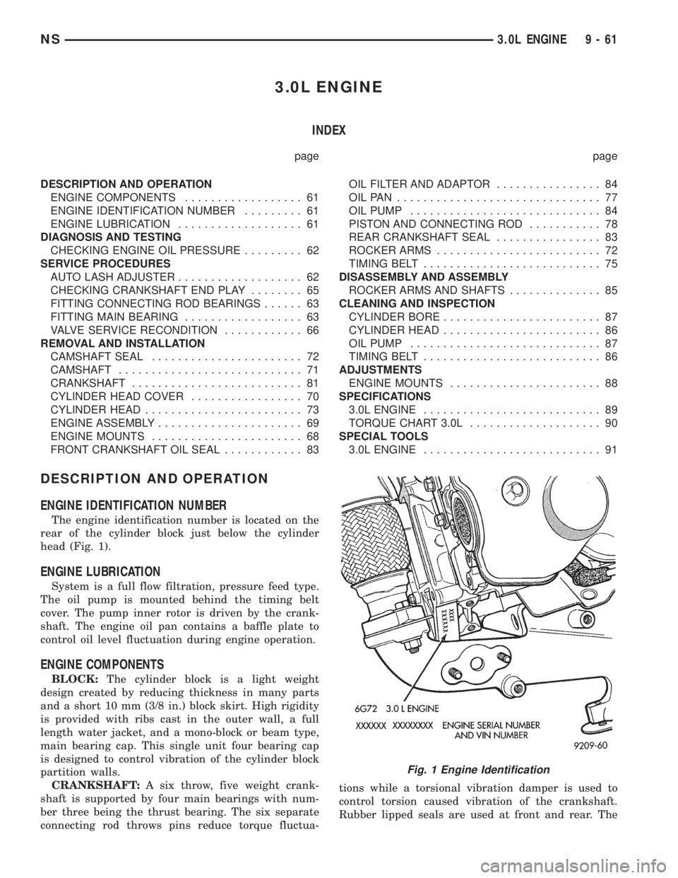
ENGINE IDENTIFICATION NUMBER
The engine identification number is located on the
rear of the cylinder block just below the cylinder
head (Fig. 1).
ENGINE LUBRICATION
System is a full flow filtration, pressure feed type.
The oil pump is mounted behind the timing belt
cover. The pump inner rotor is driven by the crank-
shaft. The engine oil pan contains a baffle plate to
control oil level fluctuation during engine operation.
ENGINE COMPONENTS
BLOCK:The cylinder block is a light weight
design created by reducing thickness in many parts
and a short 10 mm (3/8 in.) block skirt. High rigidity
is provided with ribs cast in the outer wall, a full
length water jacket, and a mono-block or beam type,
main bearing cap. This single unit four bearing cap
is designed to control vibration of the cylinder block
partition walls.
CRANKSHAFT:A six throw, five weight crank-
shaft is supported by four main bearings with num-
ber three being the thrust bearing. The six separate
connecting rod throws pins reduce torque fluctua-tions while a torsional vibration damper is used to
control torsion caused vibration of the crankshaft.
Rubber lipped seals are used at front and rear. The
Fig. 1 Engine Identification
NS3.0L ENGINE 9 - 61
Page 1112 of 1938
front seal is retained in the oil pump case and the
rear is retained in a block-mounted housing.
PISTONS:Are aluminum alloy with a steel strut,
short height, and thin wall so as to be autothermic
and light weight. The piston head with valve
recesses, in combination with the cylinder head,
forms a compact spherical head with clearance for
total valve lift with pistons at top dead center. The
piston skirt, top and second ring lands are finished to
a tapered roughness for oil retention and high resis-
tance to scuffing. Piston pins, pressed into place, join
the pistons to the connecting rods.
CYLINDER HEAD:The alloy cylinder heads fea-
ture cross-flow type intake and exhaust ports. Valve
guides and inserts are hardened cast iron. Valves of
heat resistance steel are arranged in a V with each
camshaft on center. To improve combustion speed the
chambers are a compact spherical design with a
squish area of approximately 30 percent of the piston
top area. The cylinder heads are common to either
cylinder bank by reversing the direction of installa-
tion.
CAMSHAFTS:Two overhead camshafts provide
valve actuation, one front (radiator side of cylinder
bank) and one rear. The front camshaft is provided
with a distributor drive and is longer. Both cam-
shafts are supported by four bearing journals, thrust
for the front camshaft is taken at journal two and
the rear at journal three. Front and rear camshaft
driving sprockets are interchangeable. The sprockets
and the engine water pump are driven by a single
notched timing belt.
ROCKER ARM SHAFTS:The shafts are retained
by the camshaft bearing journal caps. Four shafts are
used, one for each intake and exhaust rocker arm
assembly on each cylinder head. The hollow shafts
provide a duct for lubricating oil flow from the cylin-
der head to the valve mechanisms.
ROCKER ARMS:Are of light weight die-cast with
roller type follower operating against the cam shaft.
The valve actuating end of the rocker arms are
machined to retain hydraulic lash adjusters, elimi-
nating valve lash adjustment.
VALVES:Are made of heat resistant steel, valve
springs are especially designed to be short. The valve
spring wire cross-section is oval shaped and provides
the same spring tension as longer springs. Valve
spring retainers, locks and seals are conventional.
INTAKE MANIFOLD:The aluminum alloy mani-
fold is a cross type with long runners to improve
inertia. The runners, attaching below at the cylinder
head, also attach above and support an air plenum.
The air plenum chamber absorbs air pulsations cre-
ated during the suction phase of each cylinder.
EXHAUST MANIFOLDS:Both manifolds are a
log style made of ductile cast iron. Exhaust gasses,collected from the front cylinder bank, leave the front
manifold through an end outlet and are fed through
an upper crossover tube to the rear manifold. The
collected exhaust from both manifolds are combined,
and exit to the exhaust pipe through an articulated
joint.
DIAGNOSIS AND TESTING
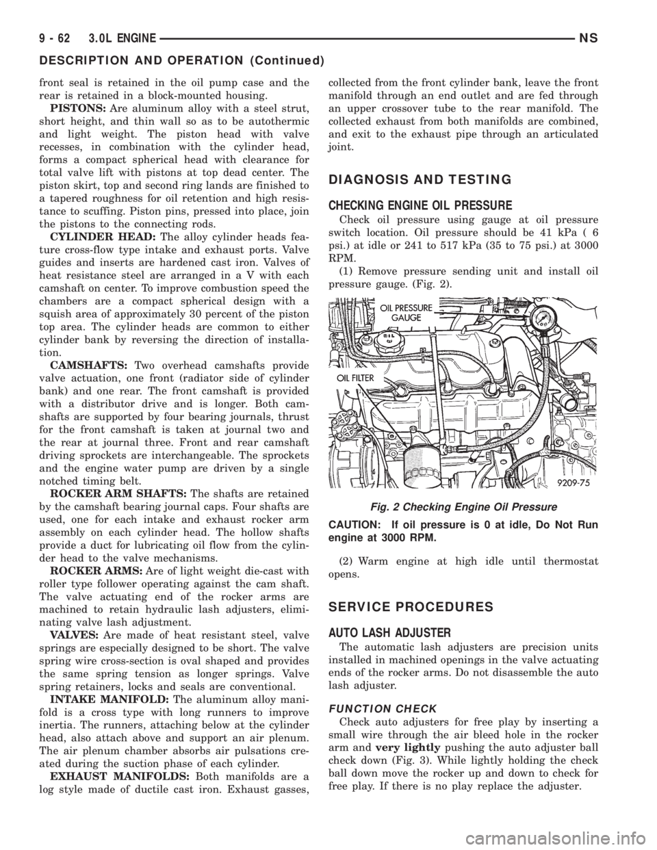
CHECKING ENGINE OIL PRESSURE
Check oil pressure using gauge at oil pressure
switch location. Oil pressure should be 41 kPa ( 6
psi.) at idle or 241 to 517 kPa (35 to 75 psi.) at 3000
RPM.
(1) Remove pressure sending unit and install oil
pressure gauge. (Fig. 2).
CAUTION: If oil pressure is 0 at idle, Do Not Run
engine at 3000 RPM.
(2) Warm engine at high idle until thermostat
opens.
SERVICE PROCEDURES
AUTO LASH ADJUSTER
The automatic lash adjusters are precision units
installed in machined openings in the valve actuating
ends of the rocker arms. Do not disassemble the auto
lash adjuster.
FUNCTION CHECK
Check auto adjusters for free play by inserting a
small wire through the air bleed hole in the rocker
arm andvery lightlypushing the auto adjuster ball
check down (Fig. 3). While lightly holding the check
ball down move the rocker up and down to check for
free play. If there is no play replace the adjuster.
Fig. 2 Checking Engine Oil Pressure
9 - 62 3.0L ENGINENS
DESCRIPTION AND OPERATION (Continued)