1996 CHRYSLER VOYAGER engine
[x] Cancel search: enginePage 1398 of 1938
FUEL LEVEL SENSORÐ2.0L ENGINE
Refer to the Fuel Pump Inlet Strainer for the 2.4/
3.0/3.3/3.8L engines under Removal and Installation
in the Fuel Delivery System section of group 14 for
more information.
FUEL TANKÐ2.0L ENGINE
Refer to the Fuel Tank for the 2.4/3.0/3.3/3.8L
engines under Removal and Installation in the Fuel
Delivery System section of group 14 for more infor-
mation.
FUEL INJECTORS
REMOVAL
(1) Disconnect negative cable from battery.
(2) Release fuel system pressure. Refer to Fuel
System Pressure Release procedure in this section.
(3) Disconnect fuel supply tube from rail. Refer to
Quick-Connect Fittings in the Fuel Delivery section
of this group.
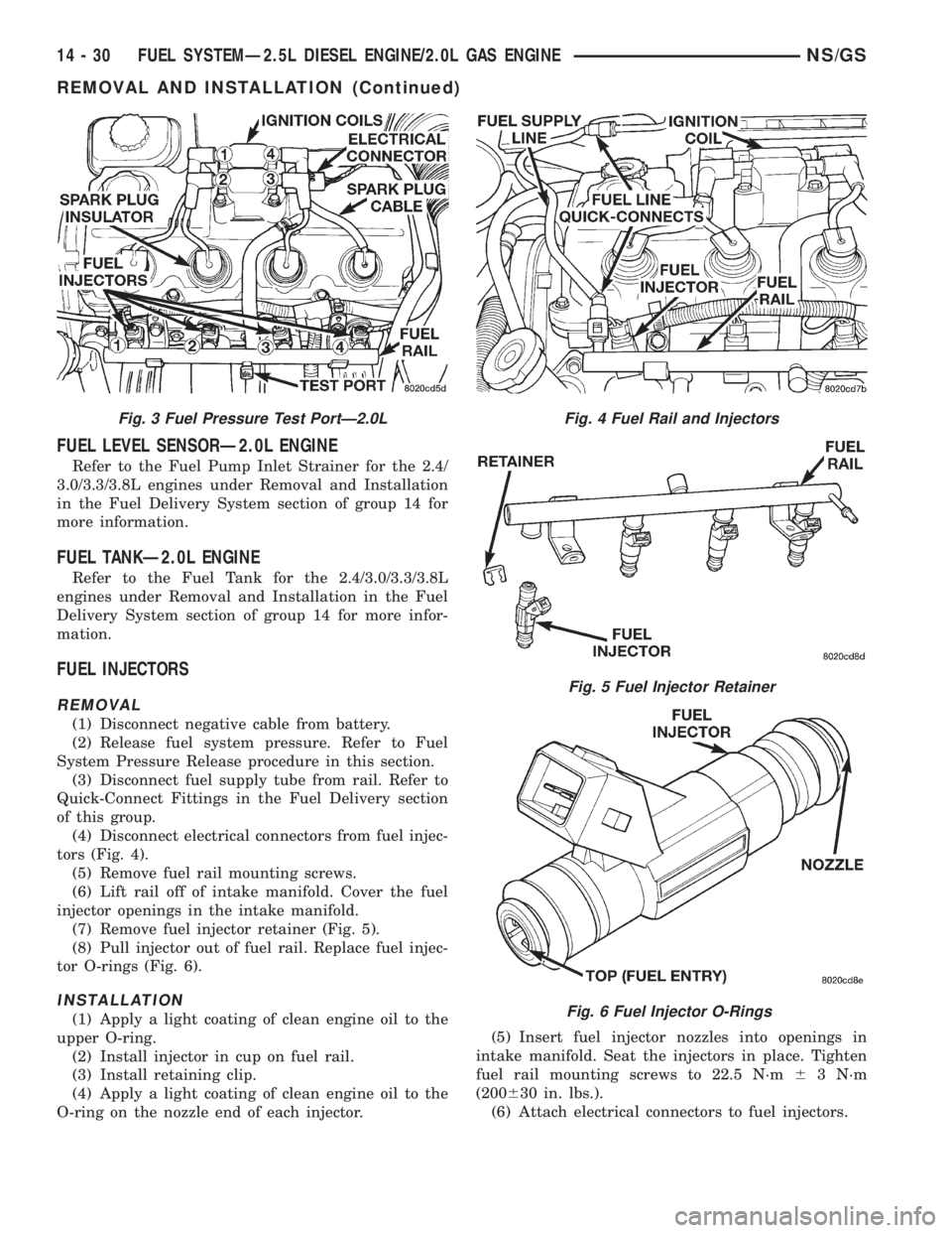
(4) Disconnect electrical connectors from fuel injec-
tors (Fig. 4).
(5) Remove fuel rail mounting screws.
(6) Lift rail off of intake manifold. Cover the fuel
injector openings in the intake manifold.
(7) Remove fuel injector retainer (Fig. 5).
(8) Pull injector out of fuel rail. Replace fuel injec-
tor O-rings (Fig. 6).
INSTALLATION
(1) Apply a light coating of clean engine oil to the
upper O-ring.
(2) Install injector in cup on fuel rail.
(3) Install retaining clip.
(4) Apply a light coating of clean engine oil to the
O-ring on the nozzle end of each injector.(5) Insert fuel injector nozzles into openings in
intake manifold. Seat the injectors in place. Tighten
fuel rail mounting screws to 22.5 N´m63 N´m
(200630 in. lbs.).
(6) Attach electrical connectors to fuel injectors.
Fig. 3 Fuel Pressure Test PortÐ2.0LFig. 4 Fuel Rail and Injectors
Fig. 5 Fuel Injector Retainer
Fig. 6 Fuel Injector O-Rings
14 - 30 FUEL SYSTEMÐ2.5L DIESEL ENGINE/2.0L GAS ENGINENS/GS
REMOVAL AND INSTALLATION (Continued)
Page 1399 of 1938
(7) Connect fuel supply tube to fuel rail. Refer to
Quick Connect Fittings in the Fuel Delivery Section
of this Group.
ACCELERATOR PEDAL
Refer to the Accelerator Pedal for the 2.4/3.0/.3.3/
3.8L engines under Removal and Installation in the
Fuel Delivery section of group 14 for more informa-
tion.
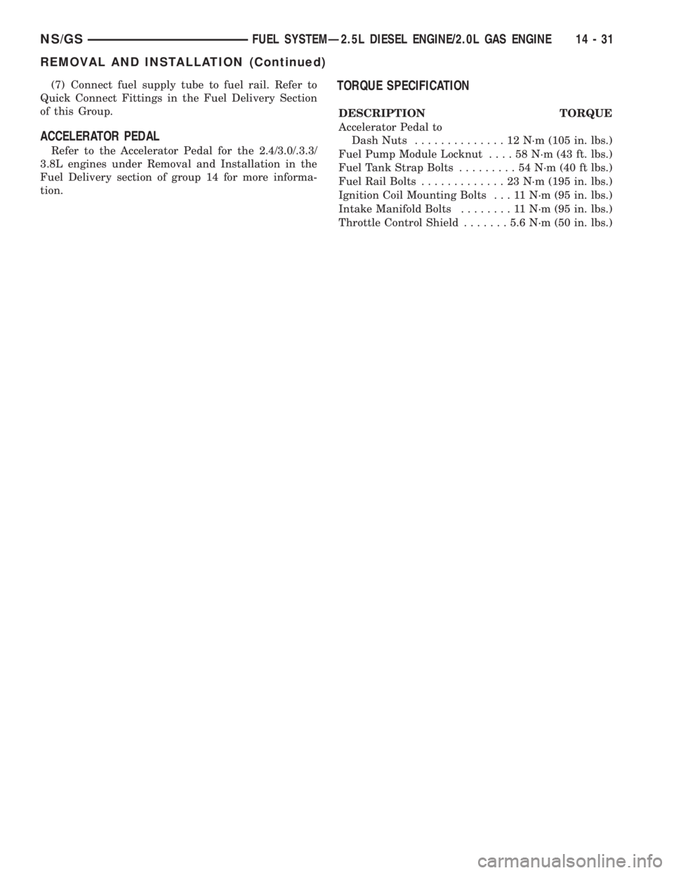
TORQUE SPECIFICATION
DESCRIPTION TORQUE
Accelerator Pedal to
Dash Nuts..............12N´m(105 in. lbs.)
Fuel Pump Module Locknut....58N´m(43ft.lbs.)
Fuel Tank Strap Bolts.........54N´m(40ftlbs.)
Fuel Rail Bolts.............23N´m(195 in. lbs.)
Ignition Coil Mounting Bolts . . . 11 N´m (95 in. lbs.)
Intake Manifold Bolts........11N´m(95in.lbs.)
Throttle Control Shield.......5.6N´m(50in.lbs.)
NS/GSFUEL SYSTEMÐ2.5L DIESEL ENGINE/2.0L GAS ENGINE 14 - 31
REMOVAL AND INSTALLATION (Continued)
Page 1400 of 1938
FUEL INJECTION SYSTEMÐ2.0L ENGINE
INDEX
page page
GENERAL INFORMATION
INTRODUCTIONÐ2.0L ENGINE............ 32
MODES OF OPERATIONÐ2.0L ENGINE..... 32
DESCRIPTION AND OPERATION
AIR CONDITIONING (A/C) RELAYÐPCM
OUTPUTÐ2.0L ENGINE................ 35
AIR CONDITIONING PRESSURE
TRANSDUCERÐPCM INPUTÐ
2.0L ENGINE......................... 33
AIR CONDITIONING SWITCH SENSEÐ
PCM INPUTÐ2.0L ENGINE.............. 33
AUTOMATIC SHUTDOWN (ASD) SENSEÐ
PCM INPUTÐ2.0L ENGINE.............. 33
AUTOMATIC SHUTDOWN RELAYÐ
PCM OUTPUTÐ2.0L ENGINE............ 35
BATTERY VOLTAGEÐPCM INPUTÐ
2.0L ENGINE......................... 33
CAMSHAFT POSITION SENSORÐ
PCM INPUTÐ2.0L ENGINE.............. 33
CRANKSHAFT POSITION SENSORÐ
PCM INPUTÐ2.0L ENGINE.............. 33
DATA LINK CONNECTORÐPCM OUTPUTÐ
2.0L ENGINE......................... 35
ELECTRONIC EGR TRANSDUCERÐ
PCM OUTPUTÐ2.0L ENGINE............ 35
ENGINE COOLANT TEMPERATURE SENSORÐ
PCM INPUTÐ2.0L ENGINE.............. 33
FUEL INJECTORSÐPCM OUTPUTÐ
2.0L ENGINE......................... 35
FUEL PUMP RELAYÐPCM OUTPUTÐ
2.0L ENGINE......................... 35
GENERATOR FIELDÐPCM OUTPUTÐ
2.0L ENGINE......................... 35
HEATED OXYGEN SENSORÐPCM INPUTÐ
2.0L ENGINE......................... 33
IDLE AIR CONTROL MOTORÐPCM OUTPUTÐ
2.0L ENGINE......................... 35
IGNITION COILÐPCM OUTPUTÐ
2.0L ENGINE......................... 36KNOCK SENSORÐPCM INPUTÐ
2.0L ENGINE......................... 34
MALFUNCTION INDICATOR (CHECK ENGINE)
LAMPÐPCM OUTPUTÐ2.0L ENGINE...... 36
MANIFOLD ABSOLUTE PRESSURE
(MAP SENSOR)ÐPCM INPUTÐ
2.0L ENGINE......................... 34
POWERTRAIN CONTROL MODULEÐ
2.0L ENGINE......................... 33
RADIATOR FAN CONTROL MODULEÐ
PCM OUTPUTÐ2.0L ENGINE............ 36
SPEED CONTROL SOLENOIDSÐ
PCM OUTPUTÐ2.0L ENGINE............ 36
SPEED CONTROLÐPCM INPUTÐ
2.0L ENGINE......................... 34
STARTER RELAYÐPCM OUTPUTÐ
2.0L ENGINE......................... 35
SYSTEM DIAGNOSISÐ2.0L ENGINE........ 33
TACHOMETERÐPCM OUTPUTÐ
2.0L ENGINE......................... 36
THROTTLE BODYÐ2.0L ENGINE.......... 36
THROTTLE POSITION SENSOR/ IDLE AIR
CONTROL MOTORÐPCM INPUTÐ
2.0L ENGINE......................... 35
DIAGNOSIS AND TESTING
ASD AND FUEL PUMP RELAYSÐ
2.0L ENGINE......................... 39
CAMSHAFT AND CRANKSHAFT
POSITION SENSOR................... 40
ENGINE COOLANT TEMPERATURE
SENSOR............................ 40
KNOCK SENSORÐ2.0L ENGINE........... 40
MANIFOLD ABSOLUTE PRESSURE
(MAP) SENSORÐ2.0L ENGINE........... 39
THROTTLE BODY MINIMUM AIR FLOW..... 41
THROTTLE POSITION SENSOR........... 40
VISUAL INSPECTIONÐSOHC............. 36
SPECIFICATIONS
TORQUE............................. 42
GENERAL INFORMATION
INTRODUCTIONÐ2.0L ENGINE
Refer to the Introduction for 2.4/3.0/3.3/3.8L
engines under General Information in the Fuel Injec-
tion System section of group 14 for more information.
MODES OF OPERATIONÐ2.0L ENGINE
Refer to the Modes of Operation for 2.4/3.0/3.3/3.8L
engines under General Information in the Fuel Injec-
tion System section of group 14 for more information.
14 - 32 FUEL SYSTEMÐ2.5L DIESEL ENGINE/2.0L GAS ENGINENS/GS
Page 1401 of 1938
DESCRIPTION AND OPERATION
SYSTEM DIAGNOSISÐ2.0L ENGINE
Refer to System diagnosis for 2.4/3.0/3.3/3.8L
engines under Description and Operation in the Fuel
Injection System section of group 14 for more infor-
mation.
POWERTRAIN CONTROL MODULEÐ2.0L ENGINE
Refer to the Powertrain Control Module for 2.4/3.0/
3.3/3.8L engines under Description and Operation in
the Fuel Injection System section of group 14 for
more information.
AIR CONDITIONING PRESSURE TRANSDUCERÐ
PCM INPUTÐ2.0L ENGINE
Refer to the Air Conditioning Pressure Transducer
for 2.4/3.0/3.3/3.8L engines under Description and
Operation in the Fuel Injection System section of
group 14 for more information.
AIR CONDITIONING SWITCH SENSEÐPCM
INPUTÐ2.0L ENGINE
Refer to the Air Conditioning Switch Sense for 2.4/
3.0/3.3/3.8L engines under Description and Operation
in the Fuel Injection System section of group 14 for
more information.
AUTOMATIC SHUTDOWN (ASD) SENSEÐPCM
INPUTÐ2.0L ENGINE
Refer to the Automatic Shutdown (ASD) Sense for
2.4/3.0/3.3/3.8L engines under Description and Oper-
ation in the Fuel Injection System section of group 14
for more information.
BATTERY VOLTAGEÐPCM INPUTÐ2.0L ENGINE
Refer to the Battery Voltage for 2.4/3.0/3.3/3.8L
engines under Description and Operation in the Fuel
Injection System section of group 14 for more infor-
mation.
CAMSHAFT POSITION SENSORÐPCM INPUTÐ
2.0L ENGINE
Refer to the Camshaft Position Sensor for 2.4L
engine under Description and Operation in the Fuel
Injection System section of group 14 for more infor-
mation.
CRANKSHAFT POSITION SENSORÐPCM
INPUTÐ2.0L ENGINE
Refer to the Crankshaft Position Sensor for 2.4L
engine under Description and Operation in the Fuel
Injection System section of group 14 for more infor-
mation.
ENGINE COOLANT TEMPERATURE SENSORÐPCM
INPUTÐ2.0L ENGINE
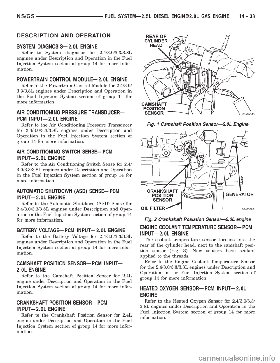
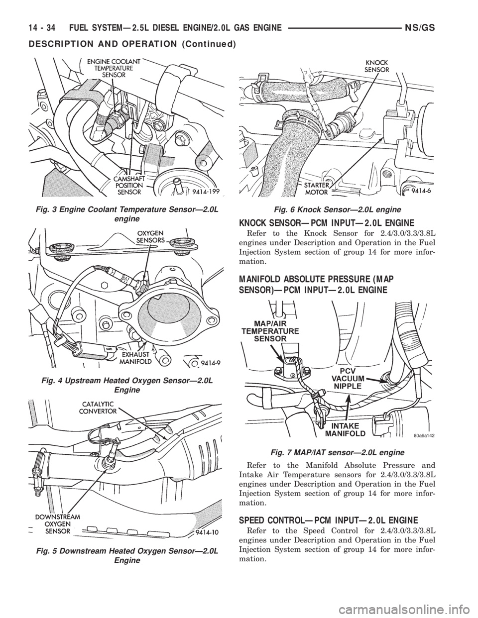
The coolant temperature sensor threads into the
rear of the cylinder head, next to the camshaft posi-
tion sensor (Fig. 3). New sensors have sealant
applied to the threads.
Refer to the Engine Coolant Temperature Sensor
for the 2.4/3.0/3.3/3.8L engines under Description and
Operation in the Fuel Injection System section of
group 14 for more information.
HEATED OXYGEN SENSORÐPCM INPUTÐ2.0L
ENGINE
Refer to the Heated Oxygen Sensor for 2.4/3.0/3.3/
3.8L engines under Description and Operation in the
Fuel Injection System section of group 14 for more
information.
Fig. 1 Camshaft Position SensorÐ2.0L Engine
Fig. 2 Crankshaft Posistion SensorÐ2.0L engine
NS/GSFUEL SYSTEMÐ2.5L DIESEL ENGINE/2.0L GAS ENGINE 14 - 33
Page 1402 of 1938
KNOCK SENSORÐPCM INPUTÐ2.0L ENGINE
Refer to the Knock Sensor for 2.4/3.0/3.3/3.8L
engines under Description and Operation in the Fuel
Injection System section of group 14 for more infor-
mation.
MANIFOLD ABSOLUTE PRESSURE (MAP
SENSOR)ÐPCM INPUTÐ2.0L ENGINE
Refer to the Manifold Absolute Pressure and
Intake Air Temperature sensors for 2.4/3.0/3.3/3.8L
engines under Description and Operation in the Fuel
Injection System section of group 14 for more infor-
mation.
SPEED CONTROLÐPCM INPUTÐ2.0L ENGINE
Refer to the Speed Control for 2.4/3.0/3.3/3.8L
engines under Description and Operation in the Fuel
Injection System section of group 14 for more infor-
mation.
Fig. 3 Engine Coolant Temperature SensorÐ2.0L
engine
Fig. 4 Upstream Heated Oxygen SensorÐ2.0L
Engine
Fig. 5 Downstream Heated Oxygen SensorÐ2.0L
Engine
Fig. 6 Knock SensorÐ2.0L engine
Fig. 7 MAP/IAT sensorÐ2.0L engine
14 - 34 FUEL SYSTEMÐ2.5L DIESEL ENGINE/2.0L GAS ENGINENS/GS
DESCRIPTION AND OPERATION (Continued)
Page 1403 of 1938
THROTTLE POSITION SENSOR/ IDLE AIR
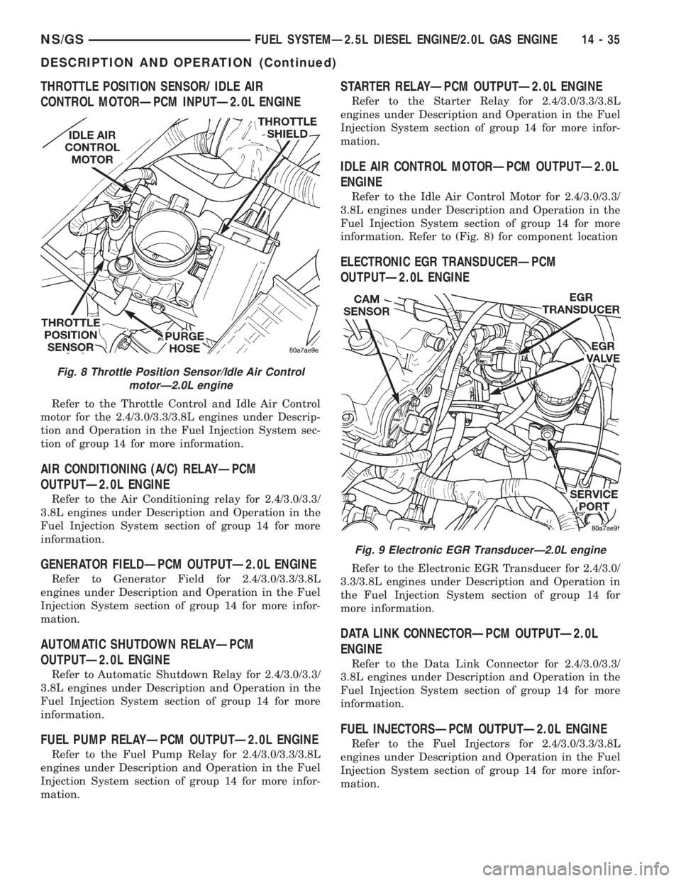
CONTROL MOTORÐPCM INPUTÐ2.0L ENGINE
Refer to the Throttle Control and Idle Air Control
motor for the 2.4/3.0/3.3/3.8L engines under Descrip-
tion and Operation in the Fuel Injection System sec-
tion of group 14 for more information.
AIR CONDITIONING (A/C) RELAYÐPCM
OUTPUTÐ2.0L ENGINE
Refer to the Air Conditioning relay for 2.4/3.0/3.3/
3.8L engines under Description and Operation in the
Fuel Injection System section of group 14 for more
information.
GENERATOR FIELDÐPCM OUTPUTÐ2.0L ENGINE
Refer to Generator Field for 2.4/3.0/3.3/3.8L
engines under Description and Operation in the Fuel
Injection System section of group 14 for more infor-
mation.
AUTOMATIC SHUTDOWN RELAYÐPCM
OUTPUTÐ2.0L ENGINE
Refer to Automatic Shutdown Relay for 2.4/3.0/3.3/
3.8L engines under Description and Operation in the
Fuel Injection System section of group 14 for more
information.
FUEL PUMP RELAYÐPCM OUTPUTÐ2.0L ENGINE
Refer to the Fuel Pump Relay for 2.4/3.0/3.3/3.8L
engines under Description and Operation in the Fuel
Injection System section of group 14 for more infor-
mation.
STARTER RELAYÐPCM OUTPUTÐ2.0L ENGINE
Refer to the Starter Relay for 2.4/3.0/3.3/3.8L
engines under Description and Operation in the Fuel
Injection System section of group 14 for more infor-
mation.
IDLE AIR CONTROL MOTORÐPCM OUTPUTÐ2.0L
ENGINE
Refer to the Idle Air Control Motor for 2.4/3.0/3.3/
3.8L engines under Description and Operation in the
Fuel Injection System section of group 14 for more
information. Refer to (Fig. 8) for component location
ELECTRONIC EGR TRANSDUCERÐPCM
OUTPUTÐ2.0L ENGINE
Refer to the Electronic EGR Transducer for 2.4/3.0/
3.3/3.8L engines under Description and Operation in
the Fuel Injection System section of group 14 for
more information.
DATA LINK CONNECTORÐPCM OUTPUTÐ2.0L
ENGINE
Refer to the Data Link Connector for 2.4/3.0/3.3/
3.8L engines under Description and Operation in the
Fuel Injection System section of group 14 for more
information.
FUEL INJECTORSÐPCM OUTPUTÐ2.0L ENGINE
Refer to the Fuel Injectors for 2.4/3.0/3.3/3.8L
engines under Description and Operation in the Fuel
Injection System section of group 14 for more infor-
mation.
Fig. 8 Throttle Position Sensor/Idle Air Control
motorÐ2.0L engine
Fig. 9 Electronic EGR TransducerÐ2.0L engine
NS/GSFUEL SYSTEMÐ2.5L DIESEL ENGINE/2.0L GAS ENGINE 14 - 35
DESCRIPTION AND OPERATION (Continued)
Page 1404 of 1938
IGNITION COILÐPCM OUTPUTÐ2.0L ENGINE
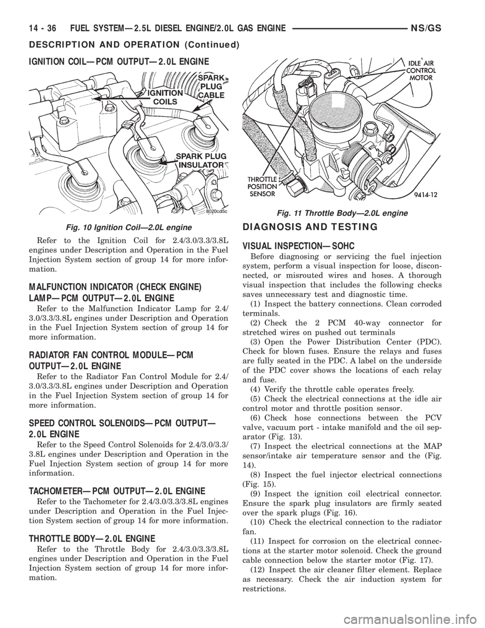
Refer to the Ignition Coil for 2.4/3.0/3.3/3.8L
engines under Description and Operation in the Fuel
Injection System section of group 14 for more infor-
mation.
MALFUNCTION INDICATOR (CHECK ENGINE)
LAMPÐPCM OUTPUTÐ2.0L ENGINE
Refer to the Malfunction Indicator Lamp for 2.4/
3.0/3.3/3.8L engines under Description and Operation
in the Fuel Injection System section of group 14 for
more information.
RADIATOR FAN CONTROL MODULEÐPCM
OUTPUTÐ2.0L ENGINE
Refer to the Radiator Fan Control Module for 2.4/
3.0/3.3/3.8L engines under Description and Operation
in the Fuel Injection System section of group 14 for
more information.
SPEED CONTROL SOLENOIDSÐPCM OUTPUTÐ
2.0L ENGINE
Refer to the Speed Control Solenoids for 2.4/3.0/3.3/
3.8L engines under Description and Operation in the
Fuel Injection System section of group 14 for more
information.
TACHOMETERÐPCM OUTPUTÐ2.0L ENGINE
Refer to the Tachometer for 2.4/3.0/3.3/3.8L engines
under Description and Operation in the Fuel Injec-
tion System section of group 14 for more information.
THROTTLE BODYÐ2.0L ENGINE
Refer to the Throttle Body for 2.4/3.0/3.3/3.8L
engines under Description and Operation in the Fuel
Injection System section of group 14 for more infor-
mation.
DIAGNOSIS AND TESTING
VISUAL INSPECTIONÐSOHC
Before diagnosing or servicing the fuel injection
system, perform a visual inspection for loose, discon-
nected, or misrouted wires and hoses. A thorough
visual inspection that includes the following checks
saves unnecessary test and diagnostic time.
(1) Inspect the battery connections. Clean corroded
terminals.
(2) Check the 2 PCM 40-way connector for
stretched wires on pushed out terminals
(3) Open the Power Distribution Center (PDC).
Check for blown fuses. Ensure the relays and fuses
are fully seated in the PDC. A label on the underside
of the PDC cover shows the locations of each relay
and fuse.
(4) Verify the throttle cable operates freely.
(5) Check the electrical connections at the idle air
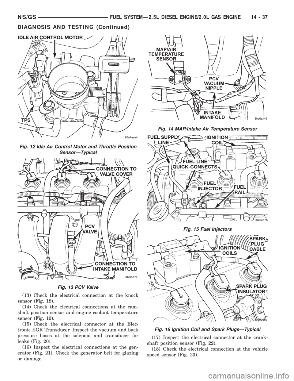
control motor and throttle position sensor.
(6) Check hose connections between the PCV
valve, vacuum port - intake manifold and the oil sep-
arator (Fig. 13).
(7) Inspect the electrical connections at the MAP
sensor/intake air temperature sensor and the (Fig.
14).
(8) Inspect the fuel injector electrical connections
(Fig. 15).
(9) Inspect the ignition coil electrical connector.
Ensure the spark plug insulators are firmly seated
over the spark plugs (Fig. 16).
(10) Check the electrical connection to the radiator
fan.
(11) Inspect for corrosion on the electrical connec-
tions at the starter motor solenoid. Check the ground
cable connection below the starter motor (Fig. 17).
(12) Inspect the air cleaner filter element. Replace
as necessary. Check the air induction system for
restrictions.
Fig. 10 Ignition CoilÐ2.0L engine
Fig. 11 Throttle BodyÐ2.0L engine
14 - 36 FUEL SYSTEMÐ2.5L DIESEL ENGINE/2.0L GAS ENGINENS/GS
DESCRIPTION AND OPERATION (Continued)
Page 1405 of 1938
(13) Check the electrical connection at the knock
sensor (Fig. 18).
(14) Check the electrical connections at the cam-
shaft position sensor and engine coolant temperature
sensor (Fig. 19).
(15) Check the electrical connector at the Elec-
tronic EGR Transducer. Inspect the vacuum and back
pressure hoses at the solenoid and transducer for
leaks (Fig. 20).
(16) Inspect the electrical connections at the gen-
erator (Fig. 21). Check the generator belt for glazing
or damage.(17) Inspect the electrical connector at the crank-
shaft position sensor (Fig. 22).
(18) Check the electrical connection at the vehicle
speed sensor (Fig. 23).
Fig. 12 Idle Air Control Motor and Throttle Position
SensorÐTypical
Fig. 13 PCV Valve
Fig. 14 MAP/Intake Air Temperature Sensor
Fig. 15 Fuel Injectors
Fig. 16 Ignition Coil and Spark PlugsÐTypical
NS/GSFUEL SYSTEMÐ2.5L DIESEL ENGINE/2.0L GAS ENGINE 14 - 37
DIAGNOSIS AND TESTING (Continued)