1996 CHRYSLER VOYAGER engine
[x] Cancel search: enginePage 1382 of 1938
START positions, fuel supply is allowed at the injec-
tion pump.
(1) Disconnect the electrical pigtail connector (test
connector) (Fig. 23) from the main engine wiring har-
ness. Do not disconnect wiring directly at solenoid.
(2) Connect the leads of a voltmeter between a
good ground and the disconnected engine wiring har-
ness.
(3) Turn the key to the ON position. Do not
attempt to start engine.
(4) 12V+ should be observed at wiring harness. If
not, refer to Group 8, Wiring for wiring schematics
and repair as necessary.
(5) T
urn the key to the START position. 12V+ should
be observed at wiring harness. If not, refer to Group 8,
Wiring for wiring schematics and repair as necessary.
The fault may be in the ignition (key) switch.
12V+ must be observed in both the ON and START
positions. If 12V+ was observed, proceed to the next
step.
(6) With key still in the ON position, connect and
disconnect the wiring harness to the solenoid. As this
is done, a clicking noise should be heard coming from
the solenoid. If not, replace solenoid. Refer to Fuel
Shutdown Solenoid in the Removal/Installation sec-
tion of this group for procedures.
HIGH-PRESSURE FUEL LINE LEAK TEST
High±pressure fuel line leaks can cause starting
problems and poor engine performance.
WARNING: DUE TO EXTREME FUEL PRESSURES
OF UP TO 45,000 KPA (6526 PSI), USE EXTREME
CAUTION WHEN INSPECTING FOR HIGH±PRESSURE
FUEL LEAKS. DO NOT GET YOUR HAND, OR ANY
PART OF YOUR BODY NEAR A SUSPECTED LEAK.
INSPECT FOR HIGH±PRESSURE FUEL LEAKS WITH
A SHEET OF CARDBOARD. HIGH FUEL INJECTION
PRESSURE CAN CAUSE PERSONAL INJURY IF
CONTACT IS MADE WITH THE SKIN.
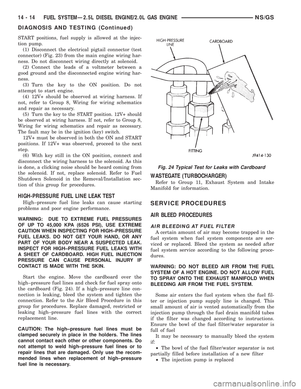
Start the engine. Move the cardboard over the
high±pressure fuel lines and check for fuel spray onto
the cardboard (Fig. 24). If a high±pressure line con-
nection is leaking, bleed the system and tighten the
connection. Refer to the Air Bleed Procedure in this
group for procedures. Replace damaged, restricted or
leaking high±pressure fuel lines with the correct
replacement line.
CAUTION: The high±pressure fuel lines must be
clamped securely in place in the holders. The lines
cannot contact each other or other components. Do
not attempt to weld high±pressure fuel lines or to
repair lines that are damaged. Only use the recom-
mended lines when replacement of high±pressure
fuel line is necessary.
WASTEGATE (TURBOCHARGER)
Refer to Group 11, Exhaust System and Intake
Manifold for information.
SERVICE PROCEDURES
AIR BLEED PROCEDURES
AIR BLEEDING AT FUEL FILTER
A certain amount of air may become trapped in the
fuel system when fuel system components are ser-
viced or replaced. Bleed the system as needed after
fuel system service according to the following proce-
dures.
WARNING: DO NOT BLEED AIR FROM THE FUEL
SYSTEM OF A HOT ENGINE. DO NOT ALLOW FUEL
TO SPRAY ONTO THE EXHAUST MANIFOLD WHEN
BLEEDING AIR FROM THE FUEL SYSTEM.
Some air enters the fuel system when the fuel fil-
ter or injection pump supply line is changed. This
small amount of air is vented automatically from the
injection pump through the fuel drain manifold tubes
if the filter was changed according to instructions.
Ensure the bowl of the fuel filter/water separator is
full of fuel
It may be necessary to manually bleed the system
if:
²The bowl of the fuel filter/water separator is not
partially filled before installation of a new filter
²The injection pump is replaced
Fig. 24 Typical Test for Leaks with Cardboard
14 - 14 FUEL SYSTEMÐ2.5L DIESEL ENGINE/2.0L GAS ENGINENS/GS
DIAGNOSIS AND TESTING (Continued)
Page 1383 of 1938
²High±pressure fuel line connections are loosened
or lines replaced
²Initial engine start±up or start±up after an
extended period of no engine operation
²Running fuel tank empty
FUEL INJECTION PUMP BLEEDING
(1) If the fuel injection pump has been replaced,
air should be bled at the overflow valve before
attempting to start engine.
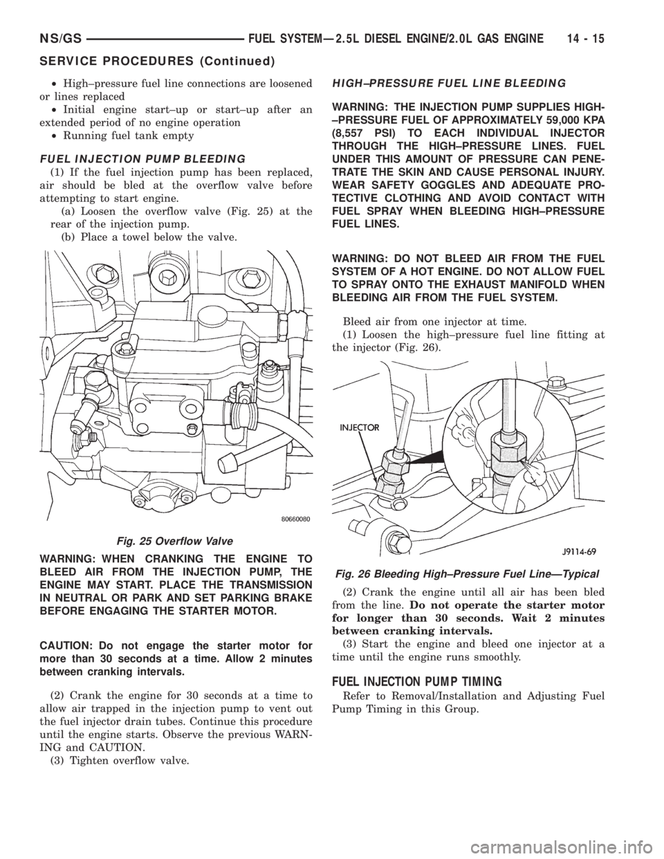
(a) Loosen the overflow valve (Fig. 25) at the
rear of the injection pump.
(b) Place a towel below the valve.
WARNING: WHEN CRANKING THE ENGINE TO
BLEED AIR FROM THE INJECTION PUMP, THE
ENGINE MAY START. PLACE THE TRANSMISSION
IN NEUTRAL OR PARK AND SET PARKING BRAKE
BEFORE ENGAGING THE STARTER MOTOR.
CAUTION: Do not engage the starter motor for
more than 30 seconds at a time. Allow 2 minutes
between cranking intervals.
(2) Crank the engine for 30 seconds at a time to
allow air trapped in the injection pump to vent out
the fuel injector drain tubes. Continue this procedure
until the engine starts. Observe the previous WARN-
ING and CAUTION.
(3) Tighten overflow valve.
HIGH±PRESSURE FUEL LINE BLEEDING
WARNING: THE INJECTION PUMP SUPPLIES HIGH-
±PRESSURE FUEL OF APPROXIMATELY 59,000 KPA
(8,557 PSI) TO EACH INDIVIDUAL INJECTOR
THROUGH THE HIGH±PRESSURE LINES. FUEL
UNDER THIS AMOUNT OF PRESSURE CAN PENE-
TRATE THE SKIN AND CAUSE PERSONAL INJURY.
WEAR SAFETY GOGGLES AND ADEQUATE PRO-
TECTIVE CLOTHING AND AVOID CONTACT WITH
FUEL SPRAY WHEN BLEEDING HIGH±PRESSURE
FUEL LINES.
WARNING: DO NOT BLEED AIR FROM THE FUEL
SYSTEM OF A HOT ENGINE. DO NOT ALLOW FUEL
TO SPRAY ONTO THE EXHAUST MANIFOLD WHEN
BLEEDING AIR FROM THE FUEL SYSTEM.
Bleed air from one injector at time.
(1) Loosen the high±pressure fuel line fitting at
the injector (Fig. 26).
(2) Crank the engine until all air has been bled
from the line.Do not operate the starter motor
for longer than 30 seconds. Wait 2 minutes
between cranking intervals.
(3) Start the engine and bleed one injector at a
time until the engine runs smoothly.
FUEL INJECTION PUMP TIMING
Refer to Removal/Installation and Adjusting Fuel
Pump Timing in this Group.
Fig. 25 Overflow Valve
Fig. 26 Bleeding High±Pressure Fuel LineÐTypical
NS/GSFUEL SYSTEMÐ2.5L DIESEL ENGINE/2.0L GAS ENGINE 14 - 15
SERVICE PROCEDURES (Continued)
Page 1384 of 1938
REMOVAL AND INSTALLATION
ACCELERATOR PEDAL
CAUTION: Be careful not to damage or kink the
cable core wire (within the cable sheathing) while
servicing the accelerator pedal or throttle cable.
REMOVAL
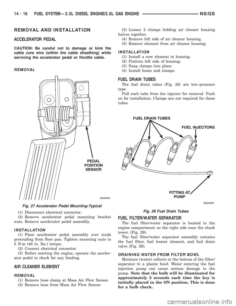
(1) Disconnect electrical connector.
(2) Remove accelerator pedal mounting bracket
nuts. Remove accelerator pedal assembly.
INSTALLATION
(1) Place accelerator pedal assembly over studs
protruding from floor pan. Tighten mounting nuts to
5 N´m (46 in. lbs.) torque.
(2) Connect electrical connector.
(3) Before starting the engine, operate the acceler-
ator pedal to check for any binding.
AIR CLEANER ELEMENT
REMOVAL
(1) Remove hose clamp at Mass Air Flow Sensor.
(2) Remove hose from Mass Air Flow Sensor.(3) Loosen 2 clamps holding air cleaner housing
halves together.
(4) Remove left side of air cleaner housing.
(5) Remove element from air cleaner housing.
INSTALLATION
(1) Install a new element in housing.
(2) Position left side of housing.
(3) Snap clamps into place.
(4) Install hoses and clamps.
FUEL DRAIN TUBES
The fuel drain tubes (Fig. 28) are low±pressure
type.
Pull each tube from the injector for removal. Push
on for installation. Clamps are not required for these
tubes.
FUEL FILTER/WATER SEPARATOR
The fuel filter/water separator is located in the
engine compartment on the right side near the shock
tower. (Fig. 29).
The fuel filter/water separator assembly contains
the fuel filter, fuel heater element, and fuel drain
valve (Fig. 29).
DRAINING WATER FROM FILTER BOWL
Moisture (water) collects at the bottom of the filter/
separator in a plastic bowl. Water entering the fuel
injection pump can cause serious damage to the
pump.Note that the bulb will be illuminated for
approximately 2 seconds each time the key is
initially placed in the ON position. This is done
for a bulb check.
Fig. 27 Accelerator Pedal Mounting-Typical
Fig. 28 Fuel Drain Tubes
14 - 16 FUEL SYSTEMÐ2.5L DIESEL ENGINE/2.0L GAS ENGINENS/GS
Page 1385 of 1938
WARNING: DO NOT ATTEMPT TO DRAIN WATER
FROM THE FILTER/SEPARATOR WITH THE ENGINE
HOT.
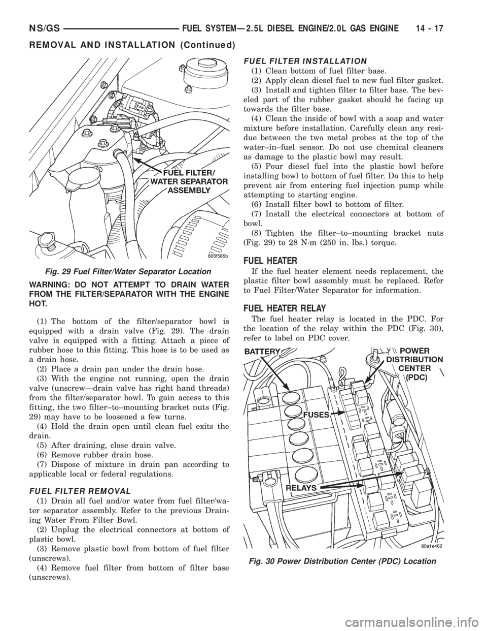
(1) The bottom of the filter/separator bowl is
equipped with a drain valve (Fig. 29). The drain
valve is equipped with a fitting. Attach a piece of
rubber hose to this fitting. This hose is to be used as
a drain hose.
(2) Place a drain pan under the drain hose.
(3) With the engine not running, open the drain
valve (unscrewÐdrain valve has right hand threads)
from the filter/separator bowl. To gain access to this
fitting, the two filter±to±mounting bracket nuts (Fig.
29) may have to be loosened a few turns.
(4) Hold the drain open until clean fuel exits the
drain.
(5) After draining, close drain valve.
(6) Remove rubber drain hose.
(7) Dispose of mixture in drain pan according to
applicable local or federal regulations.
FUEL FILTER REMOVAL
(1) Drain all fuel and/or water from fuel filter/wa-
ter separator assembly. Refer to the previous Drain-
ing Water From Filter Bowl.
(2) Unplug the electrical connectors at bottom of
plastic bowl.
(3) Remove plastic bowl from bottom of fuel filter
(unscrews).
(4) Remove fuel filter from bottom of filter base
(unscrews).
FUEL FILTER INSTALLATION
(1) Clean bottom of fuel filter base.
(2) Apply clean diesel fuel to new fuel filter gasket.
(3) Install and tighten filter to filter base. The bev-
eled part of the rubber gasket should be facing up
towards the filter base.
(4) Clean the inside of bowl with a soap and water
mixture before installation. Carefully clean any resi-
due between the two metal probes at the top of the
water±in±fuel sensor. Do not use chemical cleaners
as damage to the plastic bowl may result.
(5) Pour diesel fuel into the plastic bowl before
installing bowl to bottom of fuel filter. Do this to help
prevent air from entering fuel injection pump while
attempting to starting engine.
(6) Install filter bowl to bottom of filter.
(7) Install the electrical connectors at bottom of
bowl.
(8) Tighten the filter±to±mounting bracket nuts
(Fig. 29) to 28 N´m (250 in. lbs.) torque.
FUEL HEATER
If the fuel heater element needs replacement, the
plastic filter bowl assembly must be replaced. Refer
to Fuel Filter/Water Separator for information.
FUEL HEATER RELAY
The fuel heater relay is located in the PDC. For
the location of the relay within the PDC (Fig. 30),
refer to label on PDC cover.
Fig. 29 Fuel Filter/Water Separator Location
Fig. 30 Power Distribution Center (PDC) Location
NS/GSFUEL SYSTEMÐ2.5L DIESEL ENGINE/2.0L GAS ENGINE 14 - 17
REMOVAL AND INSTALLATION (Continued)
Page 1386 of 1938
FUEL LEVEL SENSOR
REMOVAL
Remove fuel reservoir module. Refer to Fuel Reser-
voir Module in this section.
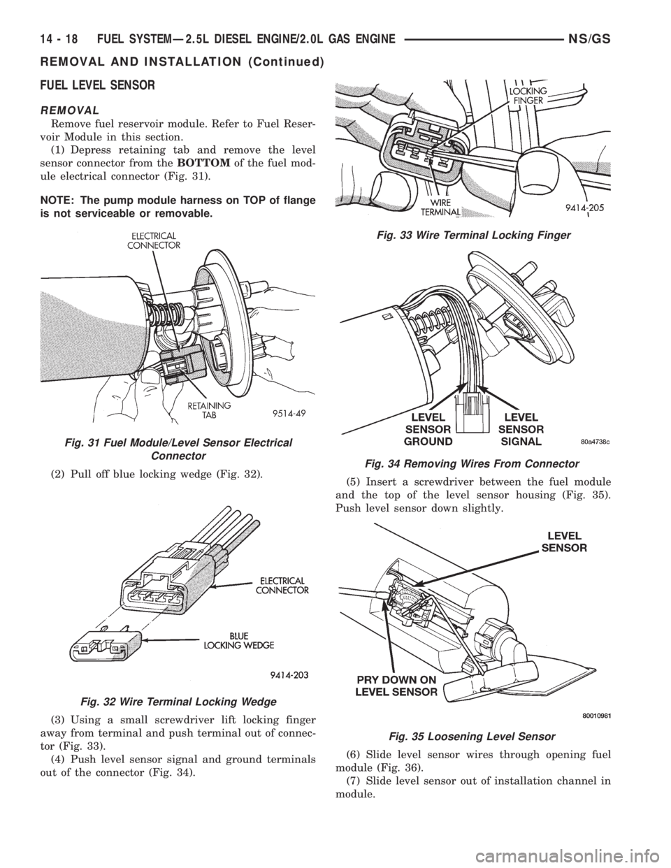
(1) Depress retaining tab and remove the level
sensor connector from theBOTTOMof the fuel mod-
ule electrical connector (Fig. 31).
NOTE: The pump module harness on TOP of flange
is not serviceable or removable.
(2) Pull off blue locking wedge (Fig. 32).
(3) Using a small screwdriver lift locking finger
away from terminal and push terminal out of connec-
tor (Fig. 33).
(4) Push level sensor signal and ground terminals
out of the connector (Fig. 34).(5) Insert a screwdriver between the fuel module
and the top of the level sensor housing (Fig. 35).
Push level sensor down slightly.
(6) Slide level sensor wires through opening fuel
module (Fig. 36).
(7) Slide level sensor out of installation channel in
module.
Fig. 31 Fuel Module/Level Sensor Electrical
Connector
Fig. 32 Wire Terminal Locking Wedge
Fig. 33 Wire Terminal Locking Finger
Fig. 34 Removing Wires From Connector
Fig. 35 Loosening Level Sensor
14 - 18 FUEL SYSTEMÐ2.5L DIESEL ENGINE/2.0L GAS ENGINENS/GS
REMOVAL AND INSTALLATION (Continued)
Page 1387 of 1938
INSTALLATION
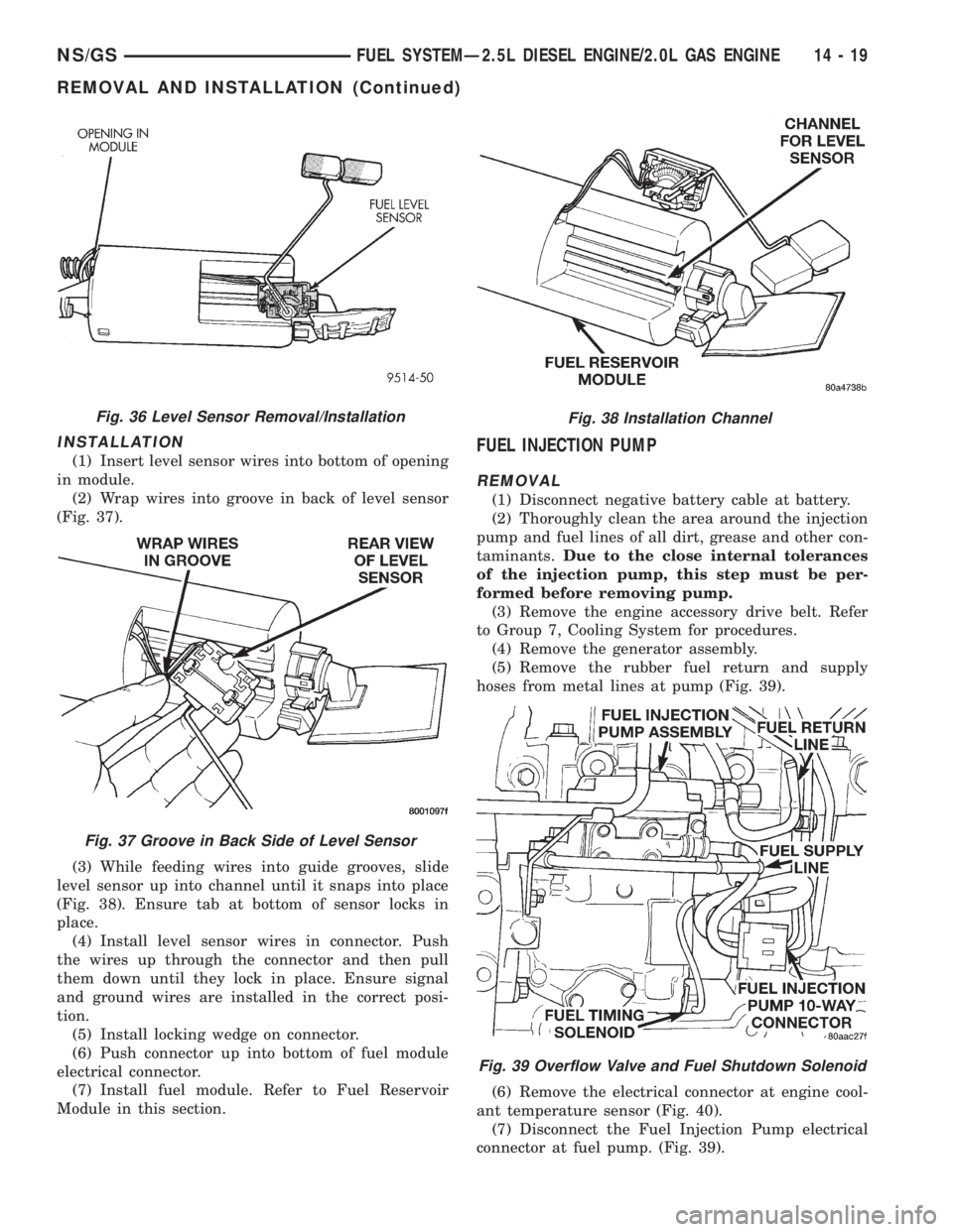
(1) Insert level sensor wires into bottom of opening
in module.
(2) Wrap wires into groove in back of level sensor
(Fig. 37).
(3) While feeding wires into guide grooves, slide
level sensor up into channel until it snaps into place
(Fig. 38). Ensure tab at bottom of sensor locks in
place.
(4) Install level sensor wires in connector. Push
the wires up through the connector and then pull
them down until they lock in place. Ensure signal
and ground wires are installed in the correct posi-
tion.
(5) Install locking wedge on connector.
(6) Push connector up into bottom of fuel module
electrical connector.
(7) Install fuel module. Refer to Fuel Reservoir
Module in this section.FUEL INJECTION PUMP
REMOVAL
(1) Disconnect negative battery cable at battery.
(2) Thoroughly clean the area around the injection
pump and fuel lines of all dirt, grease and other con-
taminants.Due to the close internal tolerances
of the injection pump, this step must be per-
formed before removing pump.
(3) Remove the engine accessory drive belt. Refer
to Group 7, Cooling System for procedures.
(4) Remove the generator assembly.
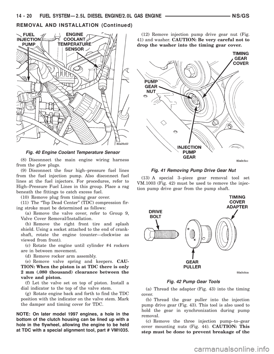
(5) Remove the rubber fuel return and supply
hoses from metal lines at pump (Fig. 39).
(6) Remove the electrical connector at engine cool-
ant temperature sensor (Fig. 40).
(7) Disconnect the Fuel Injection Pump electrical
connector at fuel pump. (Fig. 39).
Fig. 36 Level Sensor Removal/Installation
Fig. 37 Groove in Back Side of Level Sensor
Fig. 38 Installation Channel
Fig. 39 Overflow Valve and Fuel Shutdown Solenoid
NS/GSFUEL SYSTEMÐ2.5L DIESEL ENGINE/2.0L GAS ENGINE 14 - 19
REMOVAL AND INSTALLATION (Continued)
Page 1388 of 1938
(8) Disconnect the main engine wiring harness
from the glow plugs.
(9) Disconnect the four high±pressure fuel lines
from the fuel injection pump. Also disconnect fuel
lines at the fuel injectors. For procedures, refer to
High±Pressure Fuel Lines in this group. Place a rag
beneath the fittings to catch excess fuel.
(10) Remove plug from timing gear cover.
(11) The ªTop Dead Centerº (TDC) compression fir-
ing stroke must be determined as follows:
(a) Remove the valve cover, refer to Group 9,
Valve Cover Removal/Installation.
(b) Remove the right front tire and splash
shield. Using a socket attached to the end of crank-
shaft, rotate the engine (counterÐclockwise as
viewed from front).
(c) Rotate the engine until cylinder #4 rockers
are in between movement.
(d) Remove rocker arm assembly.
(e) Remove valve spring and keepers.CAU-
TION: When the piston is at TDC there is only
2 mm (.080 thousand) clearance between the
valve and piston.
(f) Let the valve set on top of piston. Install a
dial indicator to the top of the valve stem.
(g) Rotate engine back and forth to find the TDC
position with the indicator on the valve stem. Mark
the damper and timing cover for TDC.
NOTE: On later model 1997 engines, a hole in the
bottom of the clutch housing can be lined up with a
hole in the flywheel, allowing the engine to be held
at TDC with a special alignment tool, part # VM1035.(12) Remove injection pump drive gear nut (Fig.
41) and washer.CAUTION: Be very careful not to
drop the washer into the timing gear cover.
(13) A special 3±piece gear removal tool set
VM.1003 (Fig. 42) must be used to remove the injec-
tion pump drive gear from the pump shaft.
(a) Thread the adapter (Fig. 43) into the timing
cover.
(b) Thread the gear puller into the injection
pump drive gear (Fig. 43). This tool is also used to
hold the gear in synchronization during pump
removal.
(c) Remove the three injection pump±to±gear
cover mounting nuts (Fig. 44).CAUTION: This
step must be done to prevent breakage of the
Fig. 40 Engine Coolant Temperature Sensor
Fig. 41 Removing Pump Drive Gear Nut
Fig. 42 Pump Gear Tools
14 - 20 FUEL SYSTEMÐ2.5L DIESEL ENGINE/2.0L GAS ENGINENS/GS
REMOVAL AND INSTALLATION (Continued)
Page 1389 of 1938
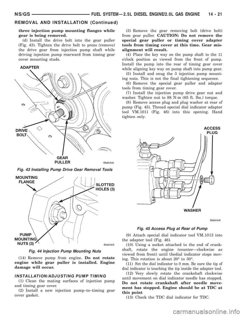
three injection pump mounting flanges while
gear is being removed.
(d) Install the drive bolt into the gear puller
(Fig. 43). Tighten the drive bolt to press (remove)
the drive gear from injection pump shaft while
driving injection pump rearward from timing gear
cover mounting studs.
(14) Remove pump from engine.Do not rotate
engine while gear puller is installed. Engine
damage will occur.
INSTALLATION/ADJUSTING PUMP TIMING
(1) Clean the mating surfaces of injection pump
and timing gear cover.
(2) Install a new injection pump±to±timing gear
cover gasket.(3) Remove the gear removing bolt (drive bolt)
from gear puller.CAUTION: Do not remove the
special gear puller or timing cover adapter
tools from timing cover at this time. Gear mis-
alignment will result.
(4) P
lace the key way on the pump shaft to the 11
o'clock position as viewed from the front of pump.
Install the pump into the rear of timing gear cover
while aligning key way on pump shaft into pump gear.
(5) Install and snug the 3 injection pump mount-
ing nuts. This is not the final tightening sequence.
(6) Remove the special gear puller and adapter
tools from timing gear cover.
(7) Install the injection pump drive gear nut and
washer. Tighten nut to 88 N´m (65 ft. lbs.) torque.
(8) Remove access plug and plug washer at rear of
pump (Fig. 45). Thread special dial indicator adapter
tool VM.1011 (Fig. 46) into this opening. Hand
tighten only.
(9) Attach special dial indicator tool VM.1013 into
the adapter tool (Fig. 46).
(10) Using a socket attached to the end of crank-
shaft, rotate the engine (counterÐclockwise as
viewed from front) until thedial indicator stops mov-
ing. This rotation is about 20É to 30É.
(11) S
et the dial indicator to 0 mm. Be sure the tip of
dial indicator is touching the tip inside the adapter tool.
(12) Very slowly rotate the crankshaft clockwise
until movement on dial indicator needle has stopped.
Do not rotate crankshaft after needle move-
ment has stopped. Engine should be at TDC at
this point
(13) Check the TDC dial indicator for TDC.
Fig. 43 Installing Pump Drive Gear Removal Tools
Fig. 44 Injection Pump Mounting Nuts
Fig. 45 Access Plug at Rear of Pump
NS/GSFUEL SYSTEMÐ2.5L DIESEL ENGINE/2.0L GAS ENGINE 14 - 21
REMOVAL AND INSTALLATION (Continued)