1996 CHRYSLER VOYAGER wheel torque
[x] Cancel search: wheel torquePage 1146 of 1938
NOTE: Worn valve guides or cocked springs are
sometimes mistaken for noisy tappets. If such is
the case, noise may be dampened by applying side
thrust on the valve spring. If noise is not apprecia-
bly reduced, it can be assumed the noise is in the
tappet. Inspect the rocker arm push rod sockets
and push rod ends for wear.
Valve tappet noise ranges from light noise to a
heavy click. A light noise is usually caused by exces-
sive leak-down around the unit plunger which will
necessitate replacing the tappet, or by the plunger
partially sticking in the tappet body cylinder. A heavy
click is caused either by a tappet check valve not
seating, or by foreign particles becoming wedged
between the plunger and the tappet body causing the
plunger to stick in the down position. This heavy
click will be accompanied by excessive clearance
between the valve stem and rocker arm as valve
closes. In either case, tappet assembly should be
removed for inspection and cleaning.
CHECKING ENGINE OIL PRESSURE
Check oil pressure using gauge at oil pressure
switch location. Oil pressure should be 34.47 kPa (5
psi.) at idle or 205 to 551 kPa (30 to 80 psi.) at 3000
RPM.
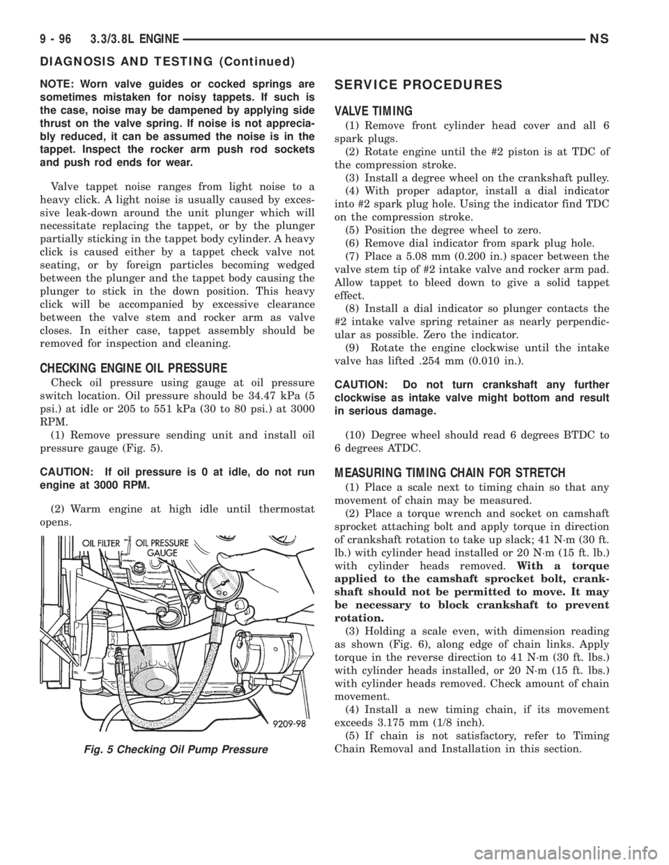
(1) Remove pressure sending unit and install oil
pressure gauge (Fig. 5).
CAUTION: If oil pressure is 0 at idle, do not run
engine at 3000 RPM.
(2) Warm engine at high idle until thermostat
opens.
SERVICE PROCEDURES
VALVE TIMING
(1) Remove front cylinder head cover and all 6
spark plugs.
(2) Rotate engine until the #2 piston is at TDC of
the compression stroke.
(3) Install a degree wheel on the crankshaft pulley.
(4) With proper adaptor, install a dial indicator
into #2 spark plug hole. Using the indicator find TDC
on the compression stroke.
(5) Position the degree wheel to zero.
(6) Remove dial indicator from spark plug hole.
(7) Place a 5.08 mm (0.200 in.) spacer between the
valve stem tip of #2 intake valve and rocker arm pad.
Allow tappet to bleed down to give a solid tappet
effect.
(8) Install a dial indicator so plunger contacts the
#2 intake valve spring retainer as nearly perpendic-
ular as possible. Zero the indicator.
(9) Rotate the engine clockwise until the intake
valve has lifted .254 mm (0.010 in.).
CAUTION: Do not turn crankshaft any further
clockwise as intake valve might bottom and result
in serious damage.
(10) Degree wheel should read 6 degrees BTDC to
6 degrees ATDC.
MEASURING TIMING CHAIN FOR STRETCH
(1) Place a scale next to timing chain so that any
movement of chain may be measured.
(2) Place a torque wrench and socket on camshaft
sprocket attaching bolt and apply torque in direction
of crankshaft rotation to take up slack; 41 N´m (30 ft.
lb.) with cylinder head installed or 20 N´m (15 ft. lb.)
with cylinder heads removed.With a torque
applied to the camshaft sprocket bolt, crank-
shaft should not be permitted to move. It may
be necessary to block crankshaft to prevent
rotation.
(3) Holding a scale even, with dimension reading
as shown (Fig. 6), along edge of chain links. Apply
torque in the reverse direction to 41 N´m (30 ft. lbs.)
with cylinder heads installed, or 20 N´m (15 ft. lbs.)
with cylinder heads removed. Check amount of chain
movement.
(4) Install a new timing chain, if its movement
exceeds 3.175 mm (1/8 inch).
(5) If chain is not satisfactory, refer to Timing
Chain Removal and Installation in this section.
Fig. 5 Checking Oil Pump Pressure
9 - 96 3.3/3.8L ENGINENS
DIAGNOSIS AND TESTING (Continued)
Page 1156 of 1938
CRANKSHAFT DAMPER
REMOVAL
(1) Disconnect negative cable from battery.
(2) Raise vehicle on hoist.
(3) Remove right wheel and inner splash shield.
(4) Remove drive belt. Refer to Group 7, Cooling
System for procedure.
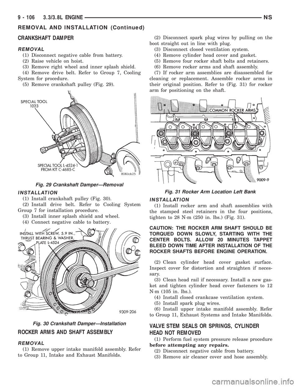
(5) Remove crankshaft pulley (Fig. 29).
INSTALLATION
(1) Install crankshaft pulley (Fig. 30).
(2) Install drive belt. Refer to Cooling System
Group 7 for installation procedure.
(3) Install inner splash shield and wheel.
(4) Connect negative cable to battery.
ROCKER ARMS AND SHAFT ASSEMBLY
REMOVAL
(1) Remove upper intake manifold assembly. Refer
to Group 11, Intake and Exhaust Manifolds.(2) Disconnect spark plug wires by pulling on the
boot straight out in line with plug.
(3) Disconnect closed ventilation system.
(4) Remove cylinder head cover and gasket.
(5) Remove four rocker shaft bolts and retainers.
(6) Remove rocker arms and shaft assembly.
(7) If rocker arm assemblies are disassembled for
cleaning or replacement. Assemble rocker arms in
their original position. Refer to (Fig. 31) for rocker
arm for positioning on the shaft.
INSTALLATION
(1) Install rocker arm and shaft assemblies with
the stamped steel retainers in the four positions,
tighten to 28 N´m (250 in. lbs.) (Fig. 31).
CAUTION: THE ROCKER ARM SHAFT SHOULD BE
TORQUED DOWN SLOWLY, STARTING WITH THE
CENTER BOLTS. ALLOW 20 MINUTES TAPPET
BLEED DOWN TIME AFTER INSTALLATION OF THE
ROCKER SHAFTS BEFORE ENGINE OPERATION.
(2) Clean cylinder head cover gasket surface.
Inspect cover for distortion and straighten if neces-
sary.
(3) Clean head rail if necessary. Install a new gas-
ket and tighten cylinder head cover fasteners to 12
N´m (105 in. lbs.).
(4) Install closed crankcase ventilation system.
(5) Install spark plug wires.
(6) Install upper intake manifold assembly. Refer
to Group 11, Exhaust Systems and Intake Manifolds.
VALVE STEM SEALS OR SPRINGS, CYLINDER
HEAD NOT REMOVED
(1) Perform fuel system pressure release procedure
before attempting any repairs.
(2) Disconnect negative cable from battery.
(3) Remove air cleaner cover and hose assembly.
Fig. 29 Crankshaft DamperÐRemoval
Fig. 30 Crankshaft DamperÐInstallation
Fig. 31 Rocker Arm Location Left Bank
9 - 106 3.3/3.8L ENGINENS
REMOVAL AND INSTALLATION (Continued)
Page 1162 of 1938
(3) Rotate crankshaft so that the oil pump drive
flats are vertical.
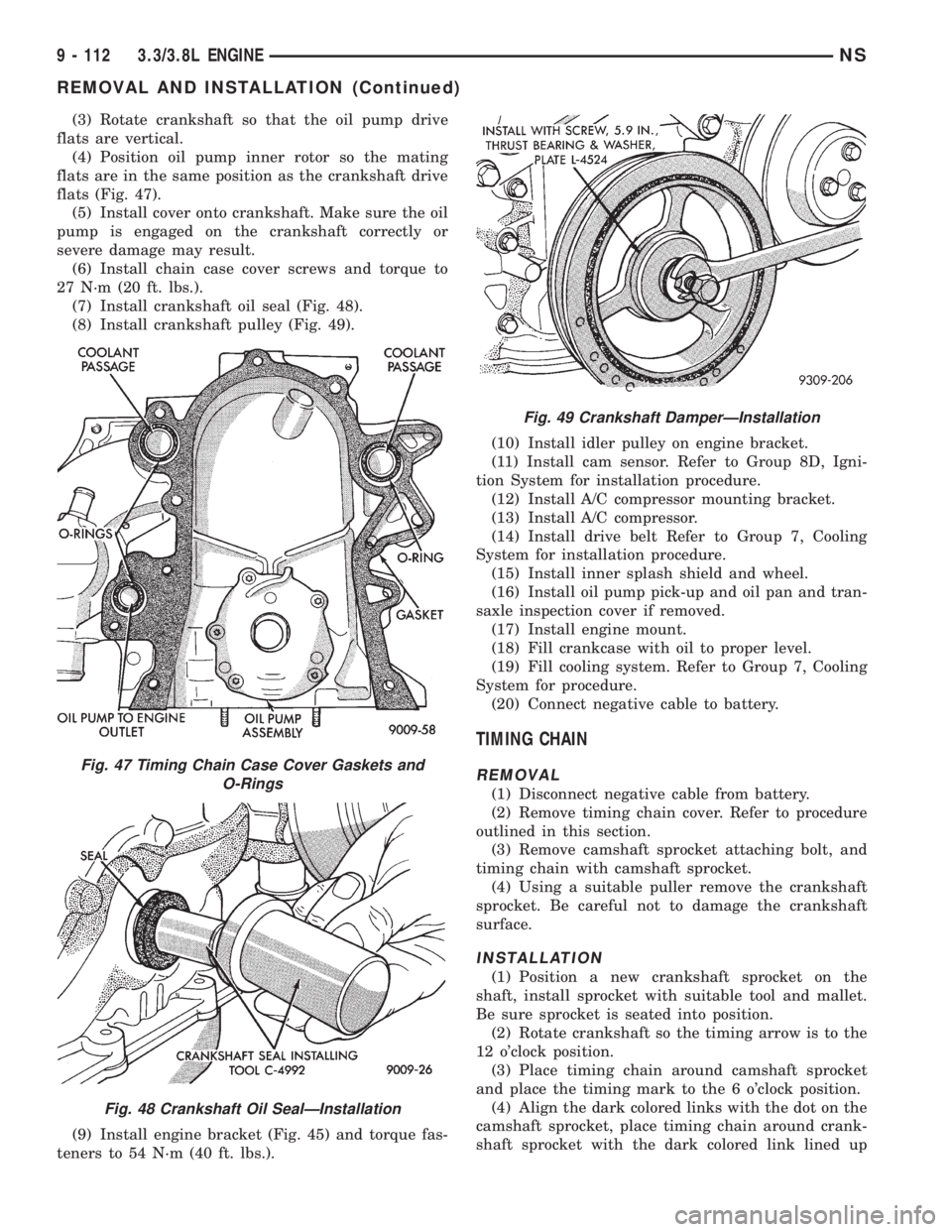
(4) Position oil pump inner rotor so the mating
flats are in the same position as the crankshaft drive
flats (Fig. 47).
(5) Install cover onto crankshaft. Make sure the oil
pump is engaged on the crankshaft correctly or
severe damage may result.
(6) Install chain case cover screws and torque to
27 N´m (20 ft. lbs.).
(7) Install crankshaft oil seal (Fig. 48).
(8) Install crankshaft pulley (Fig. 49).
(9) Install engine bracket (Fig. 45) and torque fas-
teners to 54 N´m (40 ft. lbs.).(10) Install idler pulley on engine bracket.
(11) Install cam sensor. Refer to Group 8D, Igni-
tion System for installation procedure.
(12) Install A/C compressor mounting bracket.
(13) Install A/C compressor.
(14) Install drive belt Refer to Group 7, Cooling
System for installation procedure.
(15) Install inner splash shield and wheel.
(16) Install oil pump pick-up and oil pan and tran-
saxle inspection cover if removed.
(17) Install engine mount.
(18) Fill crankcase with oil to proper level.
(19) Fill cooling system. Refer to Group 7, Cooling
System for procedure.
(20) Connect negative cable to battery.
TIMING CHAIN
REMOVAL
(1) Disconnect negative cable from battery.
(2) Remove timing chain cover. Refer to procedure
outlined in this section.
(3) Remove camshaft sprocket attaching bolt, and
timing chain with camshaft sprocket.
(4) Using a suitable puller remove the crankshaft
sprocket. Be careful not to damage the crankshaft
surface.
INSTALLATION
(1) Position a new crankshaft sprocket on the
shaft, install sprocket with suitable tool and mallet.
Be sure sprocket is seated into position.
(2) Rotate crankshaft so the timing arrow is to the
12 o'clock position.
(3) Place timing chain around camshaft sprocket
and place the timing mark to the 6 o'clock position.
(4) Align the dark colored links with the dot on the
camshaft sprocket, place timing chain around crank-
shaft sprocket with the dark colored link lined up
Fig. 47 Timing Chain Case Cover Gaskets and
O-Rings
Fig. 48 Crankshaft Oil SealÐInstallation
Fig. 49 Crankshaft DamperÐInstallation
9 - 112 3.3/3.8L ENGINENS
REMOVAL AND INSTALLATION (Continued)
Page 1181 of 1938
SPLASH LUBRICATION
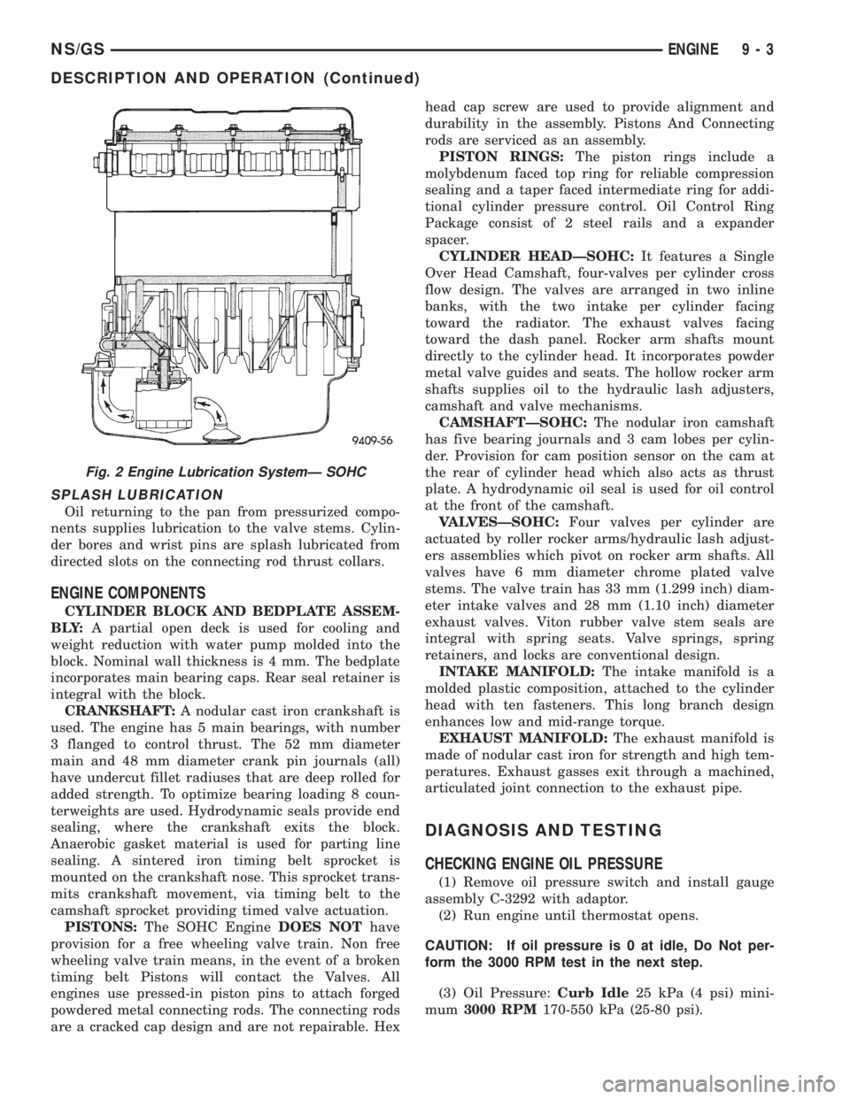
Oil returning to the pan from pressurized compo-
nents supplies lubrication to the valve stems. Cylin-
der bores and wrist pins are splash lubricated from
directed slots on the connecting rod thrust collars.
ENGINE COMPONENTS
CYLINDER BLOCK AND BEDPLATE ASSEM-
B LY:A partial open deck is used for cooling and
weight reduction with water pump molded into the
block. Nominal wall thickness is 4 mm. The bedplate
incorporates main bearing caps. Rear seal retainer is
integral with the block.
CRANKSHAFT:A nodular cast iron crankshaft is
used. The engine has 5 main bearings, with number
3 flanged to control thrust. The 52 mm diameter
main and 48 mm diameter crank pin journals (all)
have undercut fillet radiuses that are deep rolled for
added strength. To optimize bearing loading 8 coun-
terweights are used. Hydrodynamic seals provide end
sealing, where the crankshaft exits the block.
Anaerobic gasket material is used for parting line
sealing. A sintered iron timing belt sprocket is
mounted on the crankshaft nose. This sprocket trans-
mits crankshaft movement, via timing belt to the
camshaft sprocket providing timed valve actuation.
PISTONS:The SOHC EngineDOES NOThave
provision for a free wheeling valve train. Non free
wheeling valve train means, in the event of a broken
timing belt Pistons will contact the Valves. All
engines use pressed-in piston pins to attach forged
powdered metal connecting rods. The connecting rods
are a cracked cap design and are not repairable. Hexhead cap screw are used to provide alignment and
durability in the assembly. Pistons And Connecting
rods are serviced as an assembly.
PISTON RINGS:The piston rings include a
molybdenum faced top ring for reliable compression
sealing and a taper faced intermediate ring for addi-
tional cylinder pressure control. Oil Control Ring
Package consist of 2 steel rails and a expander
spacer.
CYLINDER HEADÐSOHC:It features a Single
Over Head Camshaft, four-valves per cylinder cross
flow design. The valves are arranged in two inline
banks, with the two intake per cylinder facing
toward the radiator. The exhaust valves facing
toward the dash panel. Rocker arm shafts mount
directly to the cylinder head. It incorporates powder
metal valve guides and seats. The hollow rocker arm
shafts supplies oil to the hydraulic lash adjusters,
camshaft and valve mechanisms.
CAMSHAFTÐSOHC:The nodular iron camshaft
has five bearing journals and 3 cam lobes per cylin-
der. Provision for cam position sensor on the cam at
the rear of cylinder head which also acts as thrust
plate. A hydrodynamic oil seal is used for oil control
at the front of the camshaft.
VALVESÐSOHC:Four valves per cylinder are
actuated by roller rocker arms/hydraulic lash adjust-
ers assemblies which pivot on rocker arm shafts. All
valves have 6 mm diameter chrome plated valve
stems. The valve train has 33 mm (1.299 inch) diam-
eter intake valves and 28 mm (1.10 inch) diameter
exhaust valves. Viton rubber valve stem seals are
integral with spring seats. Valve springs, spring
retainers, and locks are conventional design.
INTAKE MANIFOLD:The intake manifold is a
molded plastic composition, attached to the cylinder
head with ten fasteners. This long branch design
enhances low and mid-range torque.
EXHAUST MANIFOLD:The exhaust manifold is
made of nodular cast iron for strength and high tem-
peratures. Exhaust gasses exit through a machined,
articulated joint connection to the exhaust pipe.
DIAGNOSIS AND TESTING
CHECKING ENGINE OIL PRESSURE
(1) Remove oil pressure switch and install gauge
assembly C-3292 with adaptor.
(2) Run engine until thermostat opens.
CAUTION: If oil pressure is 0 at idle, Do Not per-
form the 3000 RPM test in the next step.
(3) Oil Pressure:Curb Idle25 kPa (4 psi) mini-
mum3000 RPM170-550 kPa (25-80 psi).
Fig. 2 Engine Lubrication SystemÐ SOHC
NS/GSENGINE 9 - 3
DESCRIPTION AND OPERATION (Continued)
Page 1229 of 1938
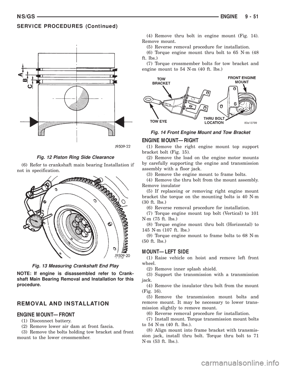
(6) Refer to crankshaft main bearing Installation if
not in specification.
NOTE: If engine is disassembled refer to Crank-
shaft Main Bearing Removal and Installation for this
procedure.
REMOVAL AND INSTALLATION
ENGINE MOUNTÐFRONT
(1) Disconnect battery.
(2) Remove lower air dam at front fascia.
(3) Remove the bolts holding tow bracket and front
mount to the lower crossmember.(4) Remove thru bolt in engine mount (Fig. 14).
Remove mount.
(5) Reverse removal procedure for installation.
(6) Torque engine mount thru bolt to 65 N´m (48
ft. lbs.)
(7) Torque crossmember bolts for tow bracket and
engine mount to 54 N´m (40 ft. lbs.)
ENGINE MOUNTÐRIGHT
(1) Remove the right engine mount top support
bracket bolt (Fig. 15).
(2) Remove the load on the engine motor mounts
by carefully supporting the engine and transmission
assembly with a floor jack.
(3) Remove the engine mount to frame bolts.
(4) Remove the thru bolt from the mount assembly.
Remove insulator
(5) If replaceing or removing right engine mount
bracket the torque on the mounting bolts is 40 N´m
(30 ft. lbs.)
(6) Reverse removal procedure for installation.
(7) Torque engine mount top bolt (Vertical) to 101
N´m (75 ft. lbs.)
(8) Torque engine mount thru bolt (Horizontal) to
145 N´m (107 ft. lbs.)
(9) Torque engine mount to frame bolts to 68 N´m
(50 ft. lbs.)
MOUNTÐLEFT SIDE
(1) Raise vehicle on hoist and remove left front
wheel.
(2) Remove inner splash shield.
(3) Support the transmission with a transmission
jack.
(4) Remove the insulator thru bolt from the mount
(Fig. 16).
(5) Remove the transmission mount bolts and
remove mount. It may be necessary to lower trans-
mission slightly to remove mount.
(6) Reverse removal procedure for installation.
(7) Install mount. Torque transmission mount bolts
to 54 N´m (40 ft. lbs.).
(8) Align mount into frame bracket with transmis-
sion jack, install thru bolt. Torque thru bolt to 71
N´m (53 ft. lbs.).
Fig. 12 Piston Ring Side Clearance
Fig. 13 Measuring Crankshaft End Play
Fig. 14 Front Engine Mount and Tow Bracket
NS/GSENGINE 9 - 51
SERVICE PROCEDURES (Continued)
Page 1239 of 1938
(3) Install cylinder head, intake manifold, and
exhaust manifold. Refer to cylinder head installation
in this section.
(4) Install push rods in original positions.
(5) Install rocker arms in original positions.
(6) Install cylinder head cover. Refer to cylinder
valve cover installation in this section.
(7) Start and operate engine. Warm up to normal
operating temperature.
CAUTION: To prevent damage to valve mechanism,
engine must not be run above fast idle until all
hydraulic tappets have filled with oil and have
become quiet.
VIBRATION DAMPER
REMOVAL
(1) Disconnect the battery cable.
(2) Raise vehicle on hoist.
(3) Remove right side lower splash shield.
(4) Remove generator, power steering belt. Refer to
Group 7, Cooling.
(5) Remove water pump belt. Refer to Group 7,
Cooling.
(6) Remove engine starter. Refer to Group, 8B for
procedure
(7) Install flywheel locking tool VM.1014 to pre-
vent engine rotation.
NOTE: Crankshaft damper nut is left handed
thread.
(8) Remove vibration damper nut.
(9) Remove vibration damper. No special tool is
needed for removal.
CAUTION: If thread sealant is used it is important
to remove all the old thread sealant from the
threads on the crankshaft.
INSTALLATION
NOTE: Before installing damper be sure the O-ring
inside the center of the damper is in its grove.
(1) Install vibration damper.
CAUTION: Correct torque on the vibration damper
nut is important or engine damage can occur.
(2) Install vibration damper nut and tighten to 441
N´m (325 ft. lbs.).
(3) Remove flywheel locking tool, and install
engine starter.(4) Install both accessary drive belts. Refer to
Group 7, Cooling.
(5) Install right splash shield.
(6) Lower vehicle.
(7) Connect the battery cable.
TIMING GEAR COVER OIL SEAL
REMOVAL
(1) Disconnect the battery cable.
(2) Remove vibration damper. Refer to vibration
damper removal in this section.
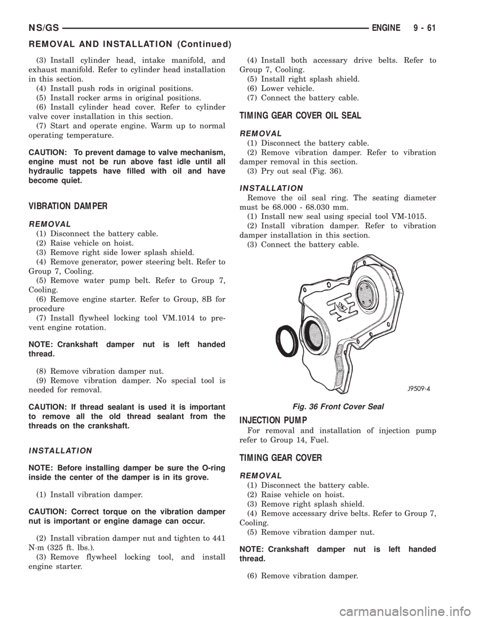
(3) Pry out seal (Fig. 36).
INSTALLATION
Remove the oil seal ring. The seating diameter
must be 68.000 - 68.030 mm.
(1) Install new seal using special tool VM-1015.
(2) Install vibration damper. Refer to vibration
damper installation in this section.
(3) Connect the battery cable.
INJECTION PUMP
For removal and installation of injection pump
refer to Group 14, Fuel.
TIMING GEAR COVER
REMOVAL
(1) Disconnect the battery cable.
(2) Raise vehicle on hoist.
(3) Remove right splash shield.
(4) Remove accessary drive belts. Refer to Group 7,
Cooling.
(5) Remove vibration damper nut.
NOTE: Crankshaft damper nut is left handed
thread.
(6) Remove vibration damper.
Fig. 36 Front Cover Seal
NS/GSENGINE 9 - 61
REMOVAL AND INSTALLATION (Continued)
Page 1242 of 1938
(13) Remove pistons and connecting rods from
block.
(14) Remove vibration damper. Refer to procedure
in this section.
(15) Remove front cover. Refer to procedure in this
section.
(16) Remove oil pump drive gear.
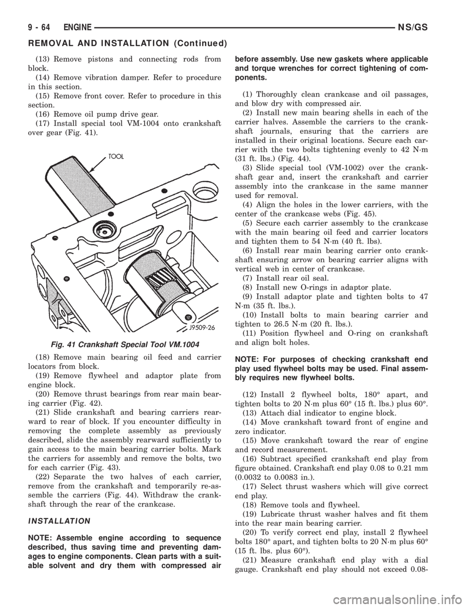
(17) Install special tool VM-1004 onto crankshaft
over gear (Fig. 41).
(18) Remove main bearing oil feed and carrier
locators from block.
(19) Remove flywheel and adaptor plate from
engine block.
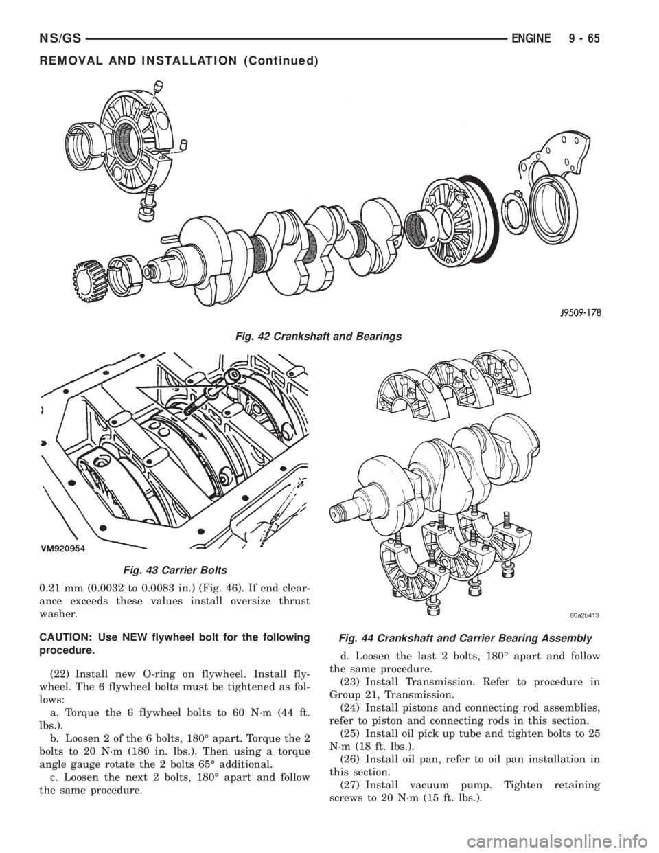
(20) Remove thrust bearings from rear main bear-
ing carrier (Fig. 42).
(21) Slide crankshaft and bearing carriers rear-
ward to rear of block. If you encounter difficulty in
removing the complete assembly as previously
described, slide the assembly rearward sufficiently to
gain access to the main bearing carrier bolts. Mark
the carriers for assembly and remove the bolts, two
for each carrier (Fig. 43).
(22) Separate the two halves of each carrier,
remove from the crankshaft and temporarily re-as-
semble the carriers (Fig. 44). Withdraw the crank-
shaft through the rear of the crankcase.
INSTALLATION
NOTE: Assemble engine according to sequence
described, thus saving time and preventing dam-
ages to engine components. Clean parts with a suit-
able solvent and dry them with compressed airbefore assembly. Use new gaskets where applicable
and torque wrenches for correct tightening of com-
ponents.
(1) Thoroughly clean crankcase and oil passages,
and blow dry with compressed air.
(2) Install new main bearing shells in each of the
carrier halves. Assemble the carriers to the crank-
shaft journals, ensuring that the carriers are
installed in their original locations. Secure each car-
rier with the two bolts tightening evenly to 42 N´m
(31 ft. lbs.) (Fig. 44).
(3) Slide special tool (VM-1002) over the crank-
shaft gear and, insert the crankshaft and carrier
assembly into the crankcase in the same manner
used for removal.
(4) Align the holes in the lower carriers, with the
center of the crankcase webs (Fig. 45).
(5) Secure each carrier assembly to the crankcase
with the main bearing oil feed and carrier locators
and tighten them to 54 N´m (40 ft. lbs).
(6) Install rear main bearing carrier onto crank-
shaft ensuring arrow on bearing carrier aligns with
vertical web in center of crankcase.
(7) Install rear oil seal.
(8) Install new O-rings in adaptor plate.
(9) Install adaptor plate and tighten bolts to 47
N´m (35 ft. lbs.).
(10) Install bolts to main bearing carrier and
tighten to 26.5 N´m (20 ft. lbs.).
(11) Position flywheel and O-ring on crankshaft
and align bolt holes.
NOTE: For purposes of checking crankshaft end
play used flywheel bolts may be used. Final assem-
bly requires new flywheel bolts.
(12) Install 2 flywheel bolts, 180É apart, and
tighten bolts to 20 N´m plus 60É (15 ft. lbs.) plus 60É.
(13) Attach dial indicator to engine block.
(14) Move crankshaft toward front of engine and
zero indicator.
(15) Move crankshaft toward the rear of engine
and record measurement.
(16) Subtract specified crankshaft end play from
figure obtained. Crankshaft end play 0.08 to 0.21 mm
(0.0032 to 0.0083 in.).
(17) Select thrust washers which will give correct
end play.
(18) Remove tools and flywheel.
(19) Lubricate thrust washer halves and fit them
into the rear main bearing carrier.
(20) To verify correct end play, install 2 flywheel
bolts 180É apart, and tighten bolts to 20 N´m plus 60É
(15 ft. lbs. plus 60É).
(21) Measure crankshaft end play with a dial
gauge. Crankshaft end play should not exceed 0.08-
Fig. 41 Crankshaft Special Tool VM.1004
9 - 64 ENGINENS/GS
REMOVAL AND INSTALLATION (Continued)
Page 1243 of 1938
0.21 mm (0.0032 to 0.0083 in.) (Fig. 46). If end clear-
ance exceeds these values install oversize thrust
washer.
CAUTION: Use NEW flywheel bolt for the following
procedure.
(22) Install new O-ring on flywheel. Install fly-
wheel. The 6 flywheel bolts must be tightened as fol-
lows:
a. Torque the 6 flywheel bolts to 60 N´m (44 ft.
lbs.).
b. Loosen 2 of the 6 bolts, 180É apart. Torque the 2
bolts to 20 N´m (180 in. lbs.). Then using a torque
angle gauge rotate the 2 bolts 65É additional.
c. Loosen the next 2 bolts, 180É apart and follow
the same procedure.d. Loosen the last 2 bolts, 180É apart and follow
the same procedure.
(23) Install Transmission. Refer to procedure in
Group 21, Transmission.
(24) Install pistons and connecting rod assemblies,
refer to piston and connecting rods in this section.
(25) Install oil pick up tube and tighten bolts to 25
N´m (18 ft. lbs.).
(26) Install oil pan, refer to oil pan installation in
this section.
(27) Install vacuum pump. Tighten retaining
screws to 20 N´m (15 ft. lbs.).
Fig. 42 Crankshaft and Bearings
Fig. 43 Carrier Bolts
Fig. 44 Crankshaft and Carrier Bearing Assembly
NS/GSENGINE 9 - 65
REMOVAL AND INSTALLATION (Continued)