1996 CHRYSLER VOYAGER wheel torque
[x] Cancel search: wheel torquePage 194 of 1938

SPECIFICATIONS
SPEED SENSOR TONE WHEEL RUNOUT
The total indicator runout allowed for both the
front and rear tone wheel measured using a dial indi-
cator is 0.15 mm (.006 in.).
WHEEL SPEED SENSOR TO TONE WHEEL
CLEARANCE
FRONT WHEEL
Minimum Clearance .35mm (.014 in.)
Maxamum Clearance 1.2 mm (.047 in.)
REAR WHEEL
Minimum Clearance .40mm (.016 in.)
Maxamum Clearance 1.2 mm (.047 in.)
BRAKE FASTENER TORQUE SPECIFICATIONS
DESCRIPTION TORQUE
BRAKE TUBES:
Tube Nuts To Fittings And
Components..............17N´m(145 in. lbs.)
BRAKE HOSE:
To Caliper Banjo Bolt..........48N´m(35ft.lbs.)
Intermediate Bracket.........12N´m(105 in. lbs.)
MASTER CYLINDER:
To Vacuum Booster
Mounting Nut............25N´m(225 in. lbs.)
FIXED PROPORTIONING VALVE:
To Frame Rail Attaching
Bolts....................14N´m(125 in. lbs.)
HEIGHT SENSING PROPORTIONING VALVE:
To Mounting Bracket
Attaching Bolts...........23N´m(200 in. lbs.)
Actuator Assembly
Adjustment Nut.............5N´m(45in.lbs.)
Mounting Bracket To
Frame Rail Bolts..........17N´m(150 in. lbs.)
JUNCTION BLOCK (NON-ABS BRAKES)
To Suspension Cradle
Mounting Bolt............28N´m(250 in. lbs.)
VACUUM BOOSTER:
To Dash Panel Mounting
Nuts....................28N´m(250 in. lbs.)DESCRIPTION TORQUE
REAR WHEEL CYLINDER:
To Support Plate Mounting
Bolts.....................8N´m(75in.lbs.)
Bleeder Screw...............10N´m(80in.lbs.)
BRAKE SUPPORT PLATE:
To Rear Axle Mounting Bolts . . .130 N´m (95 ft. lbs.)
DISC BRAKE CALIPER:
Guide Pin Bolts..............41N´m(30ft.lbs.)
Bleeder Screw..............15N´m(125 in. lbs.)
ABS HYDRAULIC CONTROL UNIT:
Mounting Bracket To
Suspension Cradle Bolts.....28N´m(250 in. lbs.)
To Mounting Bracket Isolator
Attaching Bolts............11N´m(97in.lbs.)
CAB To HCU Mounting Screws . . .2 N´m (17 in. lbs.)
WHEEL SPEED SENSOR:
To Axle Or Steering Knuckle
Mounting Bolt............12N´m(105 in. lbs.)
PARKING BRAKE:
Pedal Assembly Mounting
Bolts....................28N´m(250 in. lbs.)
REAR HUB AND BEARING:
To Axle Mounting Bolts........129 N´m (95 ft. lbs.)
WHEEL:
Stud Lug Nut........115±156 N´m (84-115 ft. lbs.)
5 - 112 BRAKESNS
Page 195 of 1938
BRAKES
CONTENTS
page page
GENERAL INFORMATION
BASE BRAKE SYSTEM COMPONENT
DESCRIPTION........................ 1
DESCRIPTION AND OPERATION
MASTER CYLINDER..................... 1
DIAGNOSIS AND TESTING
MASTER CYLINDER FLUID LEVEL CHECK . . . 2REAR DRUM BRAKE ADJUSTMENT........ 1
REMOVAL AND INSTALLATION
BRAKE PEDAL TORQUE SHAFT ASSEMBLY . . 4
FRONT PARK BRAKE CABLE AND LEVER
ASSEMBLY-RHD&LHD VEHICLES........ 2
GENERAL INFORMATION
BASE BRAKE SYSTEM COMPONENT DESCRIPTION
The standard brake system on this vehicle contains
the same components as brake systems described in
group 5 of the service manual, with the exception of
the brake pedal system and master cylinder. These
differences are mainly related to service procedures.
The major differences are as follows:
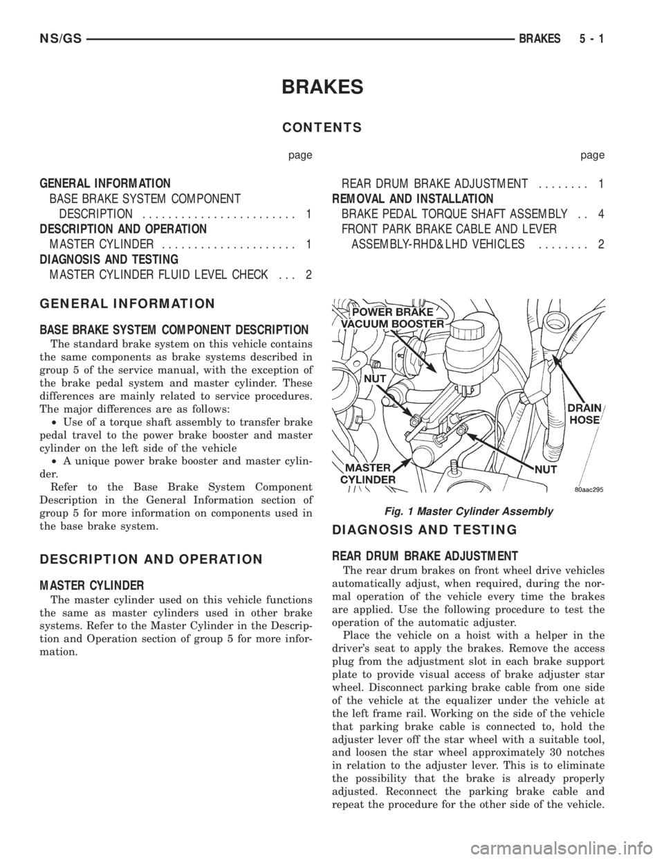
²Use of a torque shaft assembly to transfer brake
pedal travel to the power brake booster and master
cylinder on the left side of the vehicle
²A unique power brake booster and master cylin-
der.
Refer to the Base Brake System Component
Description in the General Information section of
group 5 for more information on components used in
the base brake system.
DESCRIPTION AND OPERATION
MASTER CYLINDER
The master cylinder used on this vehicle functions
the same as master cylinders used in other brake
systems. Refer to the Master Cylinder in the Descrip-
tion and Operation section of group 5 for more infor-
mation.
DIAGNOSIS AND TESTING
REAR DRUM BRAKE ADJUSTMENT
The rear drum brakes on front wheel drive vehicles
automatically adjust, when required, during the nor-
mal operation of the vehicle every time the brakes
are applied. Use the following procedure to test the
operation of the automatic adjuster.
Place the vehicle on a hoist with a helper in the
driver's seat to apply the brakes. Remove the access
plug from the adjustment slot in each brake support
plate to provide visual access of brake adjuster star
wheel. Disconnect parking brake cable from one side
of the vehicle at the equalizer under the vehicle at
the left frame rail. Working on the side of the vehicle
that parking brake cable is connected to, hold the
adjuster lever off the star wheel with a suitable tool,
and loosen the star wheel approximately 30 notches
in relation to the adjuster lever. This is to eliminate
the possibility that the brake is already properly
adjusted. Reconnect the parking brake cable and
repeat the procedure for the other side of the vehicle.
Fig. 1 Master Cylinder Assembly
NS/GSBRAKES 5 - 1
Page 205 of 1938
SERVICE DIAGNOSIS±IMPROPER CLUTCH RELEASE
CONDITION POSSIBLE CAUSES CORRECTION
CLUTCH DISC BINDS ON
INPUT SHAFT SPLINESClutch disc hub splines damaged during
installationClean, smooth, and lubricate disc and
shaft splines. Replace clutch assembly
and/or input shaft if splines are severely
damaged.
Input shaft splines rough, damaged. Clean input shaft splines. Then lube.
Corrosion or rust formations on splines
of input shaft and discClean input shaft splines and disc
splines, then lube
CLUTCH DISC RUSTED
TO FLYWHEEL AND/OR
PRESSURE PLATEOccurs in vehicles stored or not driven
for extended period of time. Also occurs
after steam cleaning if vehicle is not
used for extended period.Replace clutch assembly
CLUTCH WILL NOT
DISENGAGE PROPERLYDisc bent, distorted during transaxle
installationReplace clutch assembly
Clutch cover diaphragm spring damaged
during transaxle installationReplace clutch assembly
Release fork and (or) bushings
damagedReplace fork and (or) bushings if worn or
damaged
Clutch cable binding or routed
incorrectlyCheck and correct cable routing
Self-adjuster in cable not functioning
properly, resulting in excess cable slackPull on cable conduit at transaxle (as if
disconnecting cable) to check adjuster
operation
Clutch pedal travel restricted Verify clutch pedal can travel all the way
to the downstop on the bracket
SERVICE DIAGNOSIS±CLUTCH PEDAL NOISE
CONDITION POSSIBLE CAUSES CORRECTION
CLUTCH PEDAL MAKES
REPEATED9POP9NOISE
IN THE FIRST INCH OF
TRAVELSelf-adjusting mechanism in cable
defective (LHD Applications)Replace clutch cable (LHD Applications)
CLUTCH PEDAL
SQUEAKS WHEN
DEPRESSED TO FLOORPedal bushings worn out or inadequate
lubricationReplace or lubricate bushings
Clutch pedal assist spring fittings worn
outReplace assist spring fittings
Clutch release shaft bushings in the
bellhousing are worn outReplace release shaft and bushings
DRIVE PLATE MISALIGNMENT
Common causes of misalignment are:
²Heat warping
²Mounting drive plate on a dirty crankshaft
flange
²Incorrect bolt tightening
²Improper seating on the crankshaft shoulder
²Loose crankshaft boltsClean the crankshaft flange before mounting the
drive plate. Dirt and grease on the flange surface
may misalign the flywheel, causing excessive runout.
Use new bolts when mounting drive plate to crank-
shaft. Tighten drive plate bolts to specified torque
only. Over-tightening can distort the drive plate hub
causing excessive runout.
NS/GSCLUTCH 6 - 7
DIAGNOSIS AND TESTING (Continued)
Page 214 of 1938

ADJUSTMENTS
CLUTCH CABLE Ð LHD
The manual transaxle clutch release system has a
unique self-adjusting mechanism to compensate for
clutch disc wear. This adjuster mechanism is located
within the clutch cable assembly. The preload spring
maintains tension on the cable. This tension keeps
the clutch release bearing continuously loaded
against the fingers of the clutch cover assembly.
ADJUSTER MECHANISM FUNCTION CHECK Ð
LHD
(1) With slight pressure, pull the clutch release
lever end of the cable to draw the cable taut. Push
the clutch cable housing toward the dash panel (With
less than 20 lbs. of effort, the cable housing should
move 30-50mm.). This indicates proper adjuster
mechanism function. If the cable does not adjust,
determine if the mechanism is properly seated on the
bracket.
(2) If the adjust mechanism functions properly,
route cable to the transaxle.
(3) Insert cable into transaxle and through clutch
release lever. Ensure the cable is routed through the
smaller hole in the transaxle deck (Fig. 10).
(4) Pull down on cable and insert cable retaining
clip onto clutch cable end.
(5) Check clutch pedal position switch operation.
CLUTCH PEDAL POSITION SWITCH
The clutch pedal position switch is mounted to a
bracket located behind the clutch pedal. The switch
is held in place by four plastic wing tabs.
The clutch pedal position switch IS NOT adjust-
able. The pedal blade contacts the switch in the down
position.
SPECIFICATIONS
CLUTCH TIGHTENING REFERENCE
2.0/2.4 LITER GASOLINE ENGINE
DESCRIPTION TORQUE
Drive Plate Bolts............95N´m(70ft.lbs.)
Lower Trans. Cover.........12N´m(105 in. lbs.)
Modular Clutch Bolts.........74N´m(55ft.lbs.)
Upper Trans. Cover.........12N´m(105 in. lbs.)
2.5 LITER DIESEL ENGINE
DESCRIPTION TORQUE
Flywheel Bolts..............95N´m(70ft.lbs.)
Lower Trans. Cover.........12N´m(105 in. lbs.)
Clutch Pressure Plate Bolts....27N´m(20ft.lbs.)
Upper Trans. Cover.........12N´m(105 in. lbs.)
6 - 16 CLUTCHNS/GS
Page 284 of 1938

(7) Remove bolts holding starter to transaxle bell-
housing (Fig. 6).
(8) Remove starter.
INSTALLATION
(1) Place starter in position on vehicle.
(2) Install starter attaching bolts to transaxle bell-
housing and tighten to the proper torque.
(3) Place solenoid and B+ wires in position on
starter terminals.
(4) Install nut to hold B+ wire to terminal.
(5) Install nut to hold solenoid wire to terminal.
(6) Lower vehicle.
(7) Connect battery negative cable.
(8) Verify starter operation.
3.3/3.8L ENGINE
REMOVAL
(1) Release hood latch and open hood.
(2) Disconnect battery negative cable (Fig. 1).
(3) Hoist and support vehicle on safety stands.
(4) Remove nut holding B+ terminal to starter
solenoid (Fig. 7).
(5) Disconnect solenoid connector from starter.
(6) Remove bolts holding starter to transaxle bell-
housing.
(7) Remove starter from bellhousing (Fig. 8).
(8) Separate starter spacer from transaxle bell-
housing.INSTALLATION
(1) Place starter spacer in position on transaxle
bellhousing, flange toward flywheel.
(2) Place starter in position on bellhousing.
(3) Install starter attaching bolts to transaxle bell-
housing and tighten to the proper torque.
(4) Connect solenoid connector into starter.
(5) Install nut to hold B+ terminal to starter sole-
noid.
(6) Lower vehicle.
(7) Connect battery negative cable.
(8) Verify starter operation.
Fig. 6 Starter±3.0L Engine
Fig. 7 Wire Connectors
8B - 4 STARTING SYSTEMNS/GS
REMOVAL AND INSTALLATION (Continued)
Page 1062 of 1938
ENGINE DIAGNOSISÐMECHANICAL
CONDITION POSSIBLE CAUSES CORRECTION
NOISY VALVES 1. High or low oil level in
crankcase.1. Check for correct oil level.
2. Thin or diluted oil. 2. Change oil to correct viscosity.
3. Low oil pressure. 3. Check engine oil level.
4. Dirt in tappets/lash adjusters. 4. Replace rocker arm/hydraulic
lash adjuster assembly.
5. Worn rocker arms. 5. Inspect oil supply to rocker arms.
6. Worn tappets/lash adjusters. 6. Install new rocker arm/hydraulic
lash adjuster assembly.
7. Worn valve guides. 7. Ream and install new valves with
oversize stems.
8. Excessive runout of valve seats
on valve faces.8. Grind valve seats and valves.
9. Missing adjuster pivot. 9. Replace rocker arm/hydraulic
lash adjuster assembly.
CONNECTING ROD NOISE 1. Insuffient oil supply. 1. Check engine oil level.
2. Low oil pressure. 2. Check engine oil level. Inspect oil
pump relief valve and spring.
3. Thin or diluted oil. 3. Change oil to correct viscosity.
4. Excessive bearing clearance. 4. Measure bearings for correct
clearance. Repair as necessary.
5. Connecting rod journal
out-of-round.5. Replace crankshaft or grind
surface.
6. Misaligned connecting rods. 6. Replace bent connecting rods.
MAIN BEARING NOISE 1. Insufficient oil supply. 1. Check engine oil level.
2. Low oil pressure. 2. Check engine oil level. Inspect oil
pump relief valve and spring.
3. Thin or diluted oil. 3. Change oil to correct viscosity.
4. Excessive bearing clearance. 4. Measure bearings for correct
clearance. Repair as necessary.
5. Excessive end play. 5. Check thrust bearing for wear on
flanges.
6. Crankshaft journal out-of-round
or worn.6. Replace crankshaft or grind
journals.
7. Loose flywheel or torque
converter.7. Tighten to correct torque.
OIL PRESSURE DROP 1. Low oil level. 1. Check engine oil level.
2. Faulty oil pressure sending unit. 2. Install new sending unit.
3. Low oil pressure. 3. Check sending unit and main
bearing oil clearance.
4. Clogged oil filter. 4. Install new oil filter.
5. Worn parts in oil pump. 5. Replace worn parts or pump.
6. Thin or diluted oil. 6. Change oil to correct viscosity.
7. Excessive bearing clearance. 7. Measure bearings for correct
clearance.
8. Oil pump relief valve stuck. 8. Remove valve and inspect, clean,
or replace.
9. Oil pump suction tube loose. 9. Remove oil pan and install new
tube or clean, if necessary.
10. Oil pump cover warped or
cracked.10. Install new oil pump.
9 - 12 ENGINENS
DIAGNOSIS AND TESTING (Continued)
Page 1075 of 1938
ENGINE MOUNTÐREAR
REMOVAL
(1) Raise vehicle on hoist and remove the left
front wheel.
(2) Support the transaxle with a jack so it will not
rotate.
(3) Remove the insulator thru bolt from the
mount and rear suspension crossmember.
(4) Remove the four mount fasteners and remove
the mount.
INSTALLATION
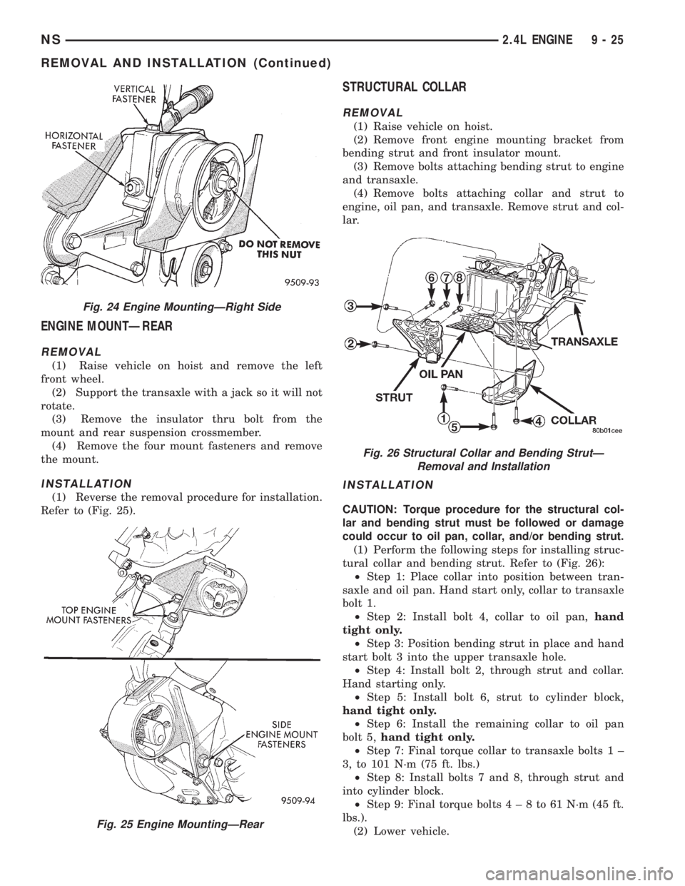
(1) Reverse the removal procedure for installation.
Refer to (Fig. 25).
STRUCTURAL COLLAR
REMOVAL
(1) Raise vehicle on hoist.
(2) Remove front engine mounting bracket from
bending strut and front insulator mount.
(3) Remove bolts attaching bending strut to engine
and transaxle.
(4) Remove bolts attaching collar and strut to
engine, oil pan, and transaxle. Remove strut and col-
lar.
INSTALLATION
CAUTION: Torque procedure for the structural col-
lar and bending strut must be followed or damage
could occur to oil pan, collar, and/or bending strut.
(1) Perform the following steps for installing struc-
tural collar and bending strut. Refer to (Fig. 26):
²Step 1: Place collar into position between tran-
saxle and oil pan. Hand start only, collar to transaxle
bolt 1.
²Step 2: Install bolt 4, collar to oil pan,hand
tight only.
²Step 3: Position bending strut in place and hand
start bolt 3 into the upper transaxle hole.
²Step 4: Install bolt 2, through strut and collar.
Hand starting only.
²Step 5: Install bolt 6, strut to cylinder block,
hand tight only.
²Step 6: Install the remaining collar to oil pan
bolt 5,hand tight only.
²Step 7: Final torque collar to transaxle bolts 1 ±
3, to 101 N´m (75 ft. lbs.)
²Step 8: Install bolts 7 and 8, through strut and
into cylinder block.
²Step 9: Final torque bolts4±8to61N´m(45ft.
lbs.).
(2) Lower vehicle.
Fig. 24 Engine MountingÐRight Side
Fig. 25 Engine MountingÐRear
Fig. 26 Structural Collar and Bending StrutÐ
Removal and Installation
NS2.4L ENGINE 9 - 25
REMOVAL AND INSTALLATION (Continued)
Page 1076 of 1938
ENGINE ASSEMBLY
REMOVAL
(1) Perform fuel pressure release procedure. Refer
to Group 14, Fuel System for procedure. Remove fuel
line to fuel rail.
(2) Disconnect battery.
(3) Remove Air cleaner and hoses.
(4) Drain cooling system. Refer to Group 7, Cooling
System for procedure.
(5) Remove upper radiator hose and remove radia-
tor fans. Refer to Group 7, Cooling System for proce-
dure.
(6) Remove lower radiator hose.
(7) Disconnect automatic transmission cooler lines
and plug, if equipped.
(8) Disconnect transmission shift linkage.
(9) Disconnect throttle body linkage.
(10) Disconnect engine wiring harness.
(11) Disconnect heater hoses.
(12) Discharge Air Conditioning System. Refer to
Group 24, Air Conditioning for procedure.
(13) Hoist vehicle and remove right inner splash
shield. Remove wheels and tires.
(14) Loosen power steering belt for pump removal.
Refer to Group 7, Cooling System for procedure.
(15) Remove axle shafts. Refer to Group 2, Suspen-
sion and Driveshafts for procedure.
(16) Disconnect exhaust pipe from manifold.
(17) Remove front and rear engine mount brackets
from the body.
(18) Remove bending braces and front engine
mount bracket. Remove transmission inspection
cover.
(19) Mark flexplate to torque converter and
remove torque converter bolts.
(20) Install front engine mount bracket.
(21) Lower vehicle.
(22) Remove power steering pump. Set pump
aside.
(23) Remove A/C lines at compressor and cap.
(24) Remove ground straps to body.
(25) Raise vehicle enough to allow engine dolly
Special Tool 6135, cradle Special Tool 6710 with
Posts Special Tool 6848 and Adaptor Special Tool
8130 to be installed under vehicle (Fig. 27).
(26) Loosen cradle posts to allow movement for
proper positioning. Locate two rear posts (right side
of engine) into the holes on the engine bedplate.
Locate the two front posts (left side of engine) on the
front engine bracket and A/C compressor bracket
(Fig. 27). Lower vehicle and position cradle mounts
until the engine is resting on mounts. Tighten
mounts to cradle frame. This will keep mounts from
moving when removing or installing engine and
transmission.(27) Lower vehicle so the weight ofONLY THE
ENGINE AND TRANSMISSIONare on the cradle.
(28) Remove engine and transmission mount bolts.
(29) Raise vehicle slowly. It may be necessary to
move the engine/transmission assembly on the cradle
to allow for removal around the body.
INSTALLATION
(1) Position engine and transmission assembly
under vehicle and slowly lower the vehicle over the
engine and transmission.
(2) Align engine and transmission mounts to
attaching points. Install mounting bolts at the right
engine and left transmission mounts. Refer to proce-
dures outlined in this section.
(3) Slowly raise vehicle enough to remove the
engine dolly and cradle Special Tools 6135 and 6710.
(4) Install axle shafts. Refer to Group 2, Suspen-
sion and Driveshafts for procedure.
(5) Install transmission and engine braces and
splash shields.
(6) Connect exhaust system to manifold. Refer to
Group 11, Exhaust System and Intake Manifold for
procedure and torque specifications.
(7) Install power steering pump. Refer to Cooling
System Group 7, Accessory Drive Section for belt ten-
sion adjustment.
(8) Install A/C compressor hoses. Refer to Group
24, Heater and Air Conditioning for procedure.
(9) Install accessory drive belts. Refer to Group 7,
Cooling System Accessory Drive Section for belt ten-
sion adjustment.
(10) Install front and rear engine mounts. Refer to
this section for procedure.
(11) Install inner splash shield. Install wheels and
tires.
(12) Connect automatic transmission cooler lines,
and shift linkage. Refer to Group 21, Transmission
for procedures.
(13) Connect fuel line and heater hoses.
(14) Install ground straps. Connect engine and
throttle body connections and harnesses. Refer to
Group 8, Electrical for procedure.
(15) Connect throttle body linkage. Refer to Group
14, Fuel System for procedure.
(16) Install radiator fans. Install radiator hoses.
Fill cooling system. Refer to Group 7, Cooling System
for filling procedure.
(17) Connect battery.
(18) Install air cleaner and hoses.
(19) Install oil filter. Fill engine crankcase with
proper oil to correct level.
(20) Start engine and run until operating temper-
ature is reached.
(21) Adjust transmission linkage, if necessary.
9 - 26 2.4L ENGINENS
REMOVAL AND INSTALLATION (Continued)