1996 CHRYSLER VOYAGER wheel torque
[x] Cancel search: wheel torquePage 1471 of 1938
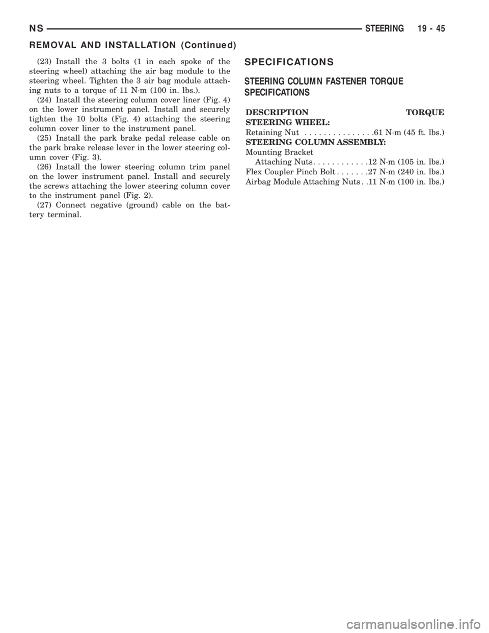
(23) Install the 3 bolts (1 in each spoke of the
steering wheel) attaching the air bag module to the
steering wheel. Tighten the 3 air bag module attach-
ing nuts to a torque of 11 N´m (100 in. lbs.).
(24) Install the steering column cover liner (Fig. 4)
on the lower instrument panel. Install and securely
tighten the 10 bolts (Fig. 4) attaching the steering
column cover liner to the instrument panel.
(25) Install the park brake pedal release cable on
the park brake release lever in the lower steering col-
umn cover (Fig. 3).
(26) Install the lower steering column trim panel
on the lower instrument panel. Install and securely
the screws attaching the lower steering column cover
to the instrument panel (Fig. 2).
(27) Connect negative (ground) cable on the bat-
tery terminal.SPECIFICATIONS
STEERING COLUMN FASTENER TORQUE
SPECIFICATIONS
DESCRIPTION TORQUE
STEERING WHEEL:
Retaining Nut...............61N´m(45ft.lbs.)
STEERING COLUMN ASSEMBLY:
Mounting Bracket
Attaching Nuts............12N´m(105 in. lbs.)
Flex Coupler Pinch Bolt.......27N´m(240 in. lbs.)
Airbag Module Attaching Nuts . .11 N´m (100 in. lbs.)
NSSTEERING 19 - 45
REMOVAL AND INSTALLATION (Continued)
Page 1476 of 1938
GENERAL INFORMATION
31TH TRANSAXLE
NOTE: Safety goggles should be worn at all times
when working on these transaxles.
This transaxle combines torque converter, three
speed transmission, final drive gearing, and differen-
tial into a front wheel drive system. The identifica-
tion markings and usage of the transaxle are charted
in Diagnosis and Tests.
NOTE: Transaxle operation requirements are differ-
ent for each vehicle and engine combination. Some
internal parts will be different to provide for this.
Therefore, when replacing parts, refer to the seven
digit part number stamped on rear of the transaxle
oil pan flange.
Within this transaxle, there are three primary
areas:
(1) Main center line plus valve body.
(2) Transfer shaft center line (includes governor
and parking sprag).
(3) Differential center line.
(4) Center distances between the main rotating
parts in these three areas are held precise to main-
tain a low noise level.
(5) The torque converter, transaxle area, and dif-
ferential are housed in an integral aluminum die
casting.The differential oil sump is common
with the transaxle sump. Separate filling of the
differential is NOT necessary.
(6) The torque converter is attached to the crank-
shaft through a flexible driving plate. Cooling of the
converter is accomplished by circulating the tran-
saxle fluid through a remote cooler. There are two
types of coolers used. An oil-to-water type cooler
located in the radiator side tank and/or an oil-to air
heat exchanger. The torque converter assembly is a
sealed unit that cannot be disassembled.
(7) The transaxle fluid is filtered by an internal fil-
ter attached to the lower side of the valve body
assembly.
(8) Engine torque is transmitted to the torque con-
verter then, through the input shaft to multiple-disc
clutches in the transaxle. The power flow depends on
the application of the clutches and bands. Refer to
Elements in Use Chart in Diagnosis and Tests sec-
tion.
(9) The transaxle consists of:
²Two multiple-disc clutches
²An overrunning clutch
²Two servos
²A hydraulic accumulator
²Two bands²Two planetary gear sets
This provides three forward ratios and a reverse
ratio. The common sun gear of the planetary gear
sets is connected to the front clutch by a driving
shell. The drive shell is splined to the sun gear and
front clutch retainer. The hydraulic system consists
of an oil pump, and a single valve body which con-
tains all of the valves except the governor valves.
The transaxle sump and differential sump are both
vented through the dipstick. Output torque from the
main center line is delivered through helical gears to
the transfer shaft. This gear set is a factor of the
final drive (axle) ratio. The shaft also carries the gov-
ernor and parking sprag. An integral helical gear on
the transfer shaft drives the differential ring gear.
The final drive gearing is completed with one of two
gear ratios of 2.98 or 3.19 depending on model and
application.
FLUID LEVEL AND CONDITION
NOTE: The transmission and differential sump have
a common oil sump with a communicating opening
between the two.
The torque converter fills in both the P Park and N
Neutral positions. Place the selector lever in P Park
to be sure that the fluid level check is accurate.The
engine should be running at idle speed for at
least one minute, with the vehicle on level
ground. This will assure complete oil level sta-
bilization between differential and transmis-
sion.The fluid should be at normal operating
temperature (approximately 82 C. or 180 F.). The
fluid level is correct if it is in the HOT region (cross-
hatched area) on the dipstick.
Low fluid level can cause a variety of conditions
because it allows the pump to take in air along with
the fluid. As in any hydraulic system, air bubbles
make the fluid spongy, therefore, pressures will be
low and build up slowly.
Improper filling can also raise the fluid level too
high. When the transaxle has too much fluid, the
gears churn up foam and cause the same conditions
which occur with a low fluid level.
In either case, the air bubbles can cause overheat-
ing, fluid oxidation, and varnishing. This can inter-
fere with normal valve, clutch, and servo operation.
Foaming can also result in fluid escaping from the
transaxle dipstick where it may be mistaken for a
leak.
Along with fluid level, it is important to check the
condition of the fluid. When the fluid smells burned,
and is contaminated with metal or friction material
particles, a complete transaxle overhaul is needed.
Be sure to examine the fluid on the dipstick closely.
21 - 2 TRANSAXLE AND POWER TRANSFER UNITNS
Page 1494 of 1938
(5) Continuity should exist only with transaxle in
Reverse position.
(6) No continuity should exist from either pin to
the case.
TRANSAXLE AND TORQUE CONVERTER REMOVAL
NOTE: Transaxle removal does NOT require engine
removal.
The transaxle and torque converter must be
removed as an assembly; otherwise, the torque con-
verter drive plate, pump bushing, or oil seal may be
damaged. The drive plate will not support a load;
therefore, none of the weight of the transaxle should
be allowed to rest on the plate during removal.
REMOVAL
(1) Disconnect negative battery cable.
(2) Remove air cleaner and hoses.
(3) Disconnect throttle linkage and shift linkage
from transaxle.
(4) Unplug torque converter clutch connector,
located near the dipstick. Unplug the gear position
switch.
(5) Remove transaxle dipstick tube.
(6) Remove the transaxle cooler lines and plug.
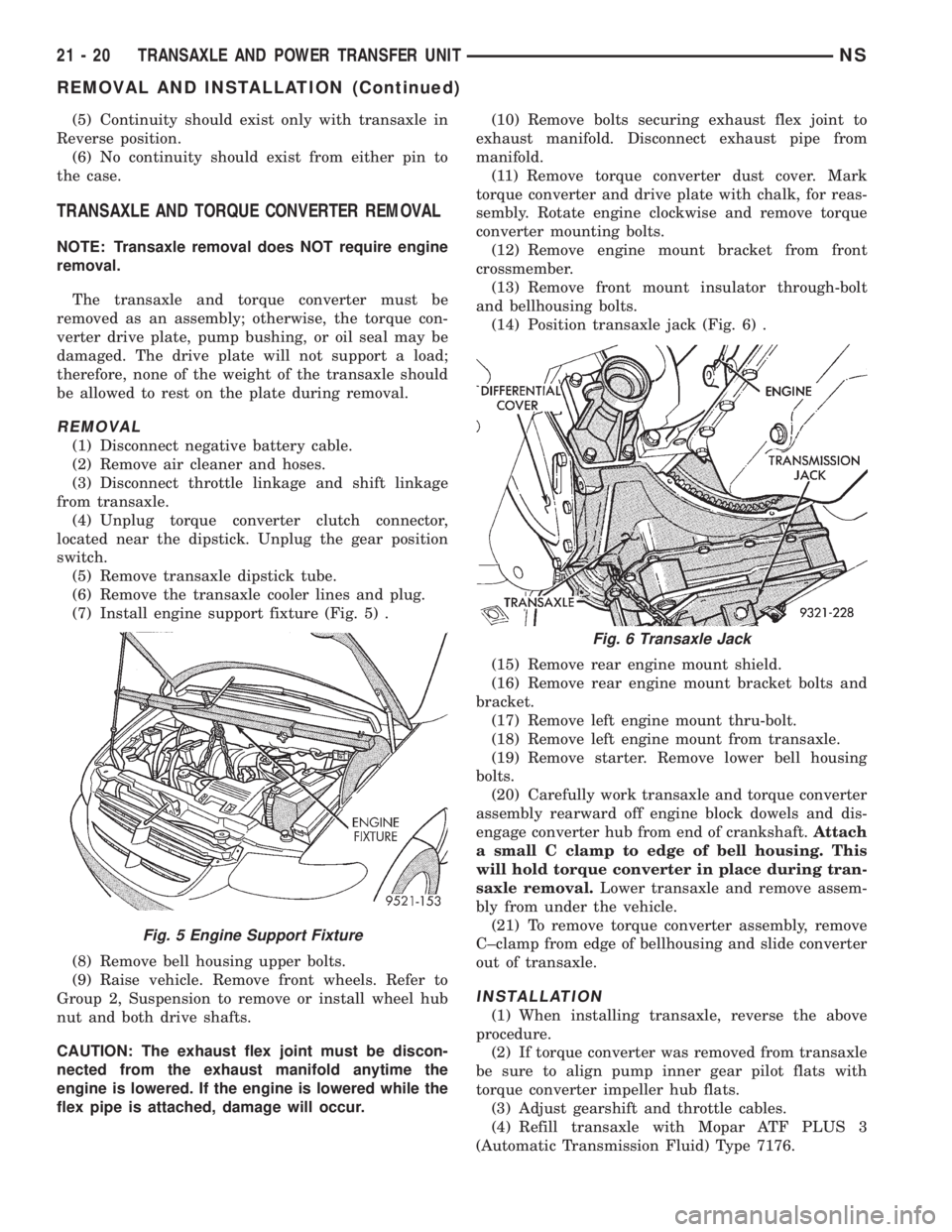
(7) Install engine support fixture (Fig. 5) .
(8) Remove bell housing upper bolts.
(9) Raise vehicle. Remove front wheels. Refer to
Group 2, Suspension to remove or install wheel hub
nut and both drive shafts.
CAUTION: The exhaust flex joint must be discon-
nected from the exhaust manifold anytime the
engine is lowered. If the engine is lowered while the
flex pipe is attached, damage will occur.(10) Remove bolts securing exhaust flex joint to
exhaust manifold. Disconnect exhaust pipe from
manifold.
(11) Remove torque converter dust cover. Mark
torque converter and drive plate with chalk, for reas-
sembly. Rotate engine clockwise and remove torque
converter mounting bolts.
(12) Remove engine mount bracket from front
crossmember.
(13) Remove front mount insulator through-bolt
and bellhousing bolts.
(14) Position transaxle jack (Fig. 6) .
(15) Remove rear engine mount shield.
(16) Remove rear engine mount bracket bolts and
bracket.
(17) Remove left engine mount thru-bolt.
(18) Remove left engine mount from transaxle.
(19) Remove starter. Remove lower bell housing
bolts.
(20) Carefully work transaxle and torque converter
assembly rearward off engine block dowels and dis-
engage converter hub from end of crankshaft.Attach
a small C clamp to edge of bell housing. This
will hold torque converter in place during tran-
saxle removal.Lower transaxle and remove assem-
bly from under the vehicle.
(21) To remove torque converter assembly, remove
C±clamp from edge of bellhousing and slide converter
out of transaxle.
INSTALLATION
(1) When installing transaxle, reverse the above
procedure.
(2) If torque converter was removed from transaxle
be sure to align pump inner gear pilot flats with
torque converter impeller hub flats.
(3) Adjust gearshift and throttle cables.
(4) Refill transaxle with Mopar ATF PLUS 3
(Automatic Transmission Fluid) Type 7176.
Fig. 5 Engine Support Fixture
Fig. 6 Transaxle Jack
21 - 20 TRANSAXLE AND POWER TRANSFER UNITNS
REMOVAL AND INSTALLATION (Continued)
Page 1549 of 1938
DIAGNOSIS AND TESTING
41TE TRANSAXLE GENERAL DIAGNOSIS
CAUTION: Before attempting any repair on a 41TE
four speed automatic transaxle, check for Diagnos-
tic Trouble Codes with the DRBIII scan tool. Always
use the Powertrain Diagnostic Test Procedure Man-
ual.
Transaxle malfunctions may be caused by these
general conditions:
²Poor engine performance
²Improper adjustments
²Hydraulic malfunctions
²Mechanical malfunctions
²Electronic malfunctions
Diagnosis of these problems should always begin
by checking the easily accessible variables: fluid level
and condition, gearshift cable adjustment. Then per-
form a road test to determine if the problem has been
corrected or that more diagnosis is necessary. If the
problem persists after the preliminary tests and cor-
rections are completed, hydraulic pressure checks
should be performed.
ROAD TEST
Prior to performing a road test, check the fluid
level.
During the road test, the transaxle should be oper-
ated in each position to check for slipping and any
variation in shifting.If vehicle operates properly at high speeds, but has
poor acceleration, the converter's overrunning clutch
may be slipping. If acceleration is normal, but high
throttle opening is needed for high speeds, the clutch
may have seized. Both of these stator defects require
replacement of the torque converter.
The clutch that is slipping can be determined by
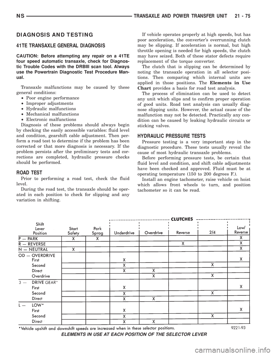
noting the transaxle operation in all selector posi-
tions. Then comparing which internal units are
applied in those positions. TheElements in Use
Chartprovides a basis for road test analysis.
The process of elimination can be used to detect
any unit which slips and to confirm proper operation
of good units. Road test analysis can usually diag-
nose slipping units. However, the actual cause of the
malfunction may not be detected. Practically any con-
dition can be caused by leaking hydraulic circuits or
sticking valves.
HYDRAULIC PRESSURE TESTS
Pressure testing is a very important step in the
diagnostic procedure. These tests usually reveal the
cause of most hydraulic transaxle problems.
Before performing pressure tests, be certain that
fluid level and condition, and shift cable adjustments
have been checked and approved. Fluid must be at
operating temperature (150 to 200 degrees F.).
Install an engine tachometer, raise vehicle on hoist
which allows front wheels to turn, and position
tachometer so it can be read.
ELEMENTS IN USE AT EACH POSITION OF THE SELECTOR LEVER
NSTRANSAXLE AND POWER TRANSFER UNIT 21 - 75
Page 1550 of 1938
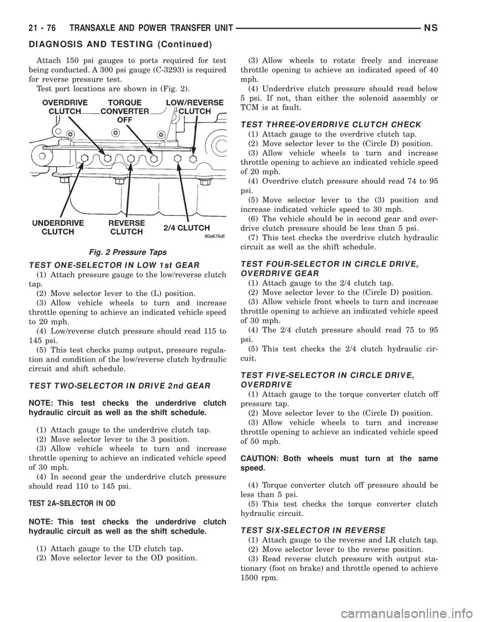
Attach 150 psi gauges to ports required for test
being conducted. A 300 psi gauge (C-3293) is required
for reverse pressure test.
Test port locations are shown in (Fig. 2).
TEST ONE-SELECTOR IN LOW 1st GEAR
(1) Attach pressure gauge to the low/reverse clutch
tap.
(2) Move selector lever to the (L) position.
(3) Allow vehicle wheels to turn and increase
throttle opening to achieve an indicated vehicle speed
to 20 mph.
(4) Low/reverse clutch pressure should read 115 to
145 psi.
(5) This test checks pump output, pressure regula-
tion and condition of the low/reverse clutch hydraulic
circuit and shift schedule.
TEST TWO-SELECTOR IN DRIVE 2nd GEAR
NOTE: This test checks the underdrive clutch
hydraulic circuit as well as the shift schedule.
(1) Attach gauge to the underdrive clutch tap.
(2) Move selector lever to the 3 position.
(3) Allow vehicle wheels to turn and increase
throttle opening to achieve an indicated vehicle speed
of 30 mph.
(4) In second gear the underdrive clutch pressure
should read 110 to 145 psi.
TEST 2A±SELECTOR IN OD
NOTE: This test checks the underdrive clutch
hydraulic circuit as well as the shift schedule.
(1) Attach gauge to the UD clutch tap.
(2) Move selector lever to the OD position.(3) Allow wheels to rotate freely and increase
throttle opening to achieve an indicated speed of 40
mph.
(4) Underdrive clutch pressure should read below
5 psi. If not, than either the solenoid assembly or
TCM is at fault.
TEST THREE-OVERDRIVE CLUTCH CHECK
(1) Attach gauge to the overdrive clutch tap.
(2) Move selector lever to the (Circle D) position.
(3) Allow vehicle wheels to turn and increase
throttle opening to achieve an indicated vehicle speed
of 20 mph.
(4) Overdrive clutch pressure should read 74 to 95
psi.
(5) Move selector lever to the (3) position and
increase indicated vehicle speed to 30 mph.
(6) The vehicle should be in second gear and over-
drive clutch pressure should be less than 5 psi.
(7) This test checks the overdrive clutch hydraulic
circuit as well as the shift schedule.
TEST FOUR-SELECTOR IN CIRCLE DRIVE,
OVERDRIVE GEAR
(1) Attach gauge to the 2/4 clutch tap.
(2) Move selector lever to the (Circle D) position.
(3) Allow vehicle front wheels to turn and increase
throttle opening to achieve an indicated vehicle speed
of 30 mph.
(4) The 2/4 clutch pressure should read 75 to 95
psi.
(5) This test checks the 2/4 clutch hydraulic cir-
cuit.
TEST FIVE-SELECTOR IN CIRCLE DRIVE,
OVERDRIVE
(1) Attach gauge to the torque converter clutch off
pressure tap.
(2) Move selector lever to the (Circle D) position.
(3) Allow vehicle wheels to turn and increase
throttle opening to achieve an indicated vehicle speed
of 50 mph.
CAUTION: Both wheels must turn at the same
speed.
(4) Torque converter clutch off pressure should be
less than 5 psi.
(5) This test checks the torque converter clutch
hydraulic circuit.
TEST SIX-SELECTOR IN REVERSE
(1) Attach gauge to the reverse and LR clutch tap.
(2) Move selector lever to the reverse position.
(3) Read reverse clutch pressure with output sta-
tionary (foot on brake) and throttle opened to achieve
1500 rpm.
Fig. 2 Pressure Taps
21 - 76 TRANSAXLE AND POWER TRANSFER UNITNS
DIAGNOSIS AND TESTING (Continued)
Page 1564 of 1938
(8) Disconnect electrical connector at transmission
range sensor.
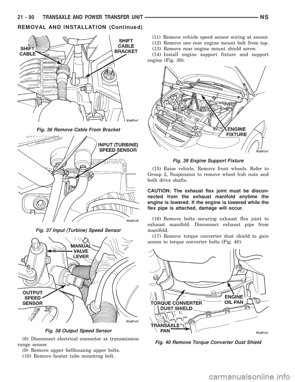
(9) Remove upper bellhousing upper bolts.
(10) Remove heater tube mounting bolt.(11) Remove vehicle speed sensor wiring at sensor.
(12) Remove one rear engine mount bolt from top.
(13) Remove rear engine mount shield screw.
(14) Install engine support fixture and support
engine (Fig. 39).
(15) Raise vehicle. Remove front wheels. Refer to
Group 2, Suspension to remove wheel hub nuts and
both drive shafts.
CAUTION: The exhaust flex joint must be discon-
nected from the exhaust manifold anytime the
engine is lowered. If the engine is lowered while the
flex pipe is attached, damage will occur.
(16) Remove bolts securing exhaust flex joint to
exhaust manifold. Disconnect exhaust pipe from
manifold.
(17) Remove torque converter dust shield to gain
access to torque converter bolts (Fig. 40).
Fig. 36 Remove Cable From Bracket
Fig. 37 Input (Turbine) Speed Sensor
Fig. 38 Output Speed Sensor
Fig. 39 Engine Support Fixture
Fig. 40 Remove Torque Converter Dust Shield
21 - 90 TRANSAXLE AND POWER TRANSFER UNITNS
REMOVAL AND INSTALLATION (Continued)
Page 1639 of 1938
POWER TRANSFER UNIT
INDEX
page page
GENERAL INFORMATION
POWER TRANSFER UNIT................ 165
DIAGNOSIS AND TESTING
FLUID LEAK DIAGNOSIS................. 167
SEAL IDENTIFICATION................... 165
REMOVAL AND INSTALLATION
DIFFERENTIAL CARRIER SEAL............ 170
END COVER BALL BEARING.............. 178
END COVER SEAL...................... 169
HALF SHAFT INNER SEAL................ 175
INPUT SHAFT COVER SEAL.............. 174
INPUT SHAFT END SEAL................. 177INPUT SHAFT SEAL..................... 169
OUTER HALF SHAFT SEAL............... 177
POWER TRANSFER UNIT (P.T.U.).......... 167
POWER TRANSFER UNIT OUTPUT SEAL.... 171
REAR COVER O-RING................... 171
ADJUSTMENTS
OUTPUT FLANGE SHIM SELECTION........ 180
SPECIFICATIONS
TORQUE............................. 180
SPECIAL TOOLS
SDP POWER TRANSFER UNIT............ 181
GENERAL INFORMATION
POWER TRANSFER UNIT
The Power Transfer Unit (P.T.U.) is attached to a
modified automatic transaxle case where the right
half shaft extension housing would normally be
located. The Transfer Unit provides the power to the
rear wheels through a hypoid ring gear and pinion
set.
The Power Transfer Unit is sealed from the tran-
saxle and has its own oil sump. The Unit uses SAE
85W-90 gear lubricant and holds 1.15 liters (1.22
quarts).
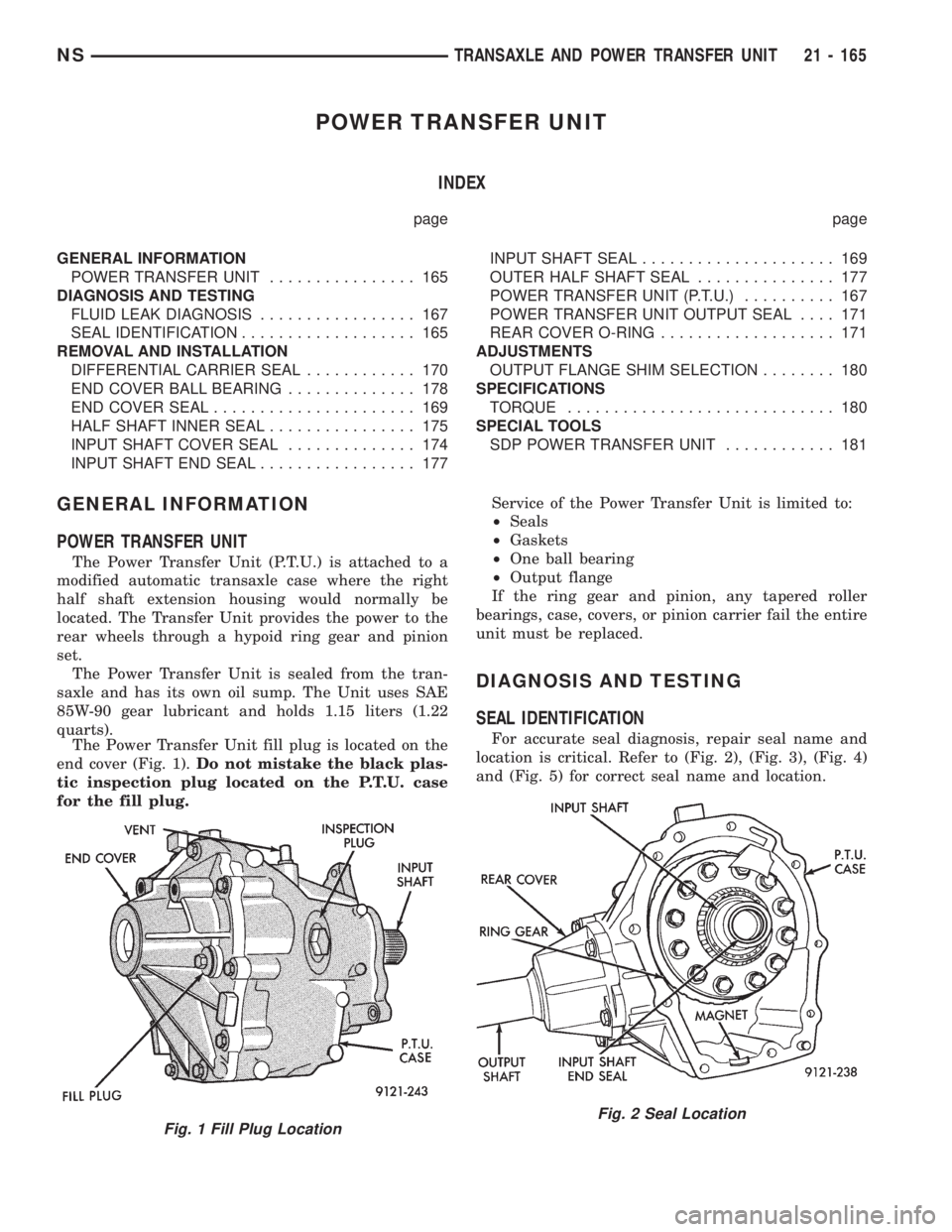
The Power Transfer Unit fill plug is located on the
end cover (Fig. 1).Do not mistake the black plas-
tic inspection plug located on the P.T.U. case
for the fill plug.Service of the Power Transfer Unit is limited to:
²Seals
²Gaskets
²One ball bearing
²Output flange
If the ring gear and pinion, any tapered roller
bearings, case, covers, or pinion carrier fail the entire
unit must be replaced.
DIAGNOSIS AND TESTING
SEAL IDENTIFICATION
For accurate seal diagnosis, repair seal name and
location is critical. Refer to (Fig. 2), (Fig. 3), (Fig. 4)
and (Fig. 5) for correct seal name and location.
Fig. 1 Fill Plug LocationFig. 2 Seal Location
NSTRANSAXLE AND POWER TRANSFER UNIT 21 - 165
Page 1724 of 1938
SERVICE PROCEDURES
TIRE AND WHEEL ROTATION (NON-DIRECTIONAL
THREAD PATTERN)
Tires on the front and rear axles operate at differ-
ent loads and perform different functions. For these
reasons, they wear at unequal rates, and tend to
develop irregular wear patterns. These effects can be
reduced by timely rotation of tires. The benefits of
rotation are especially worthwhile. Rotation will
increase tread life, help to maintain mud, snow, and
wet traction levels, and contribute to a smooth, quiet
ride.
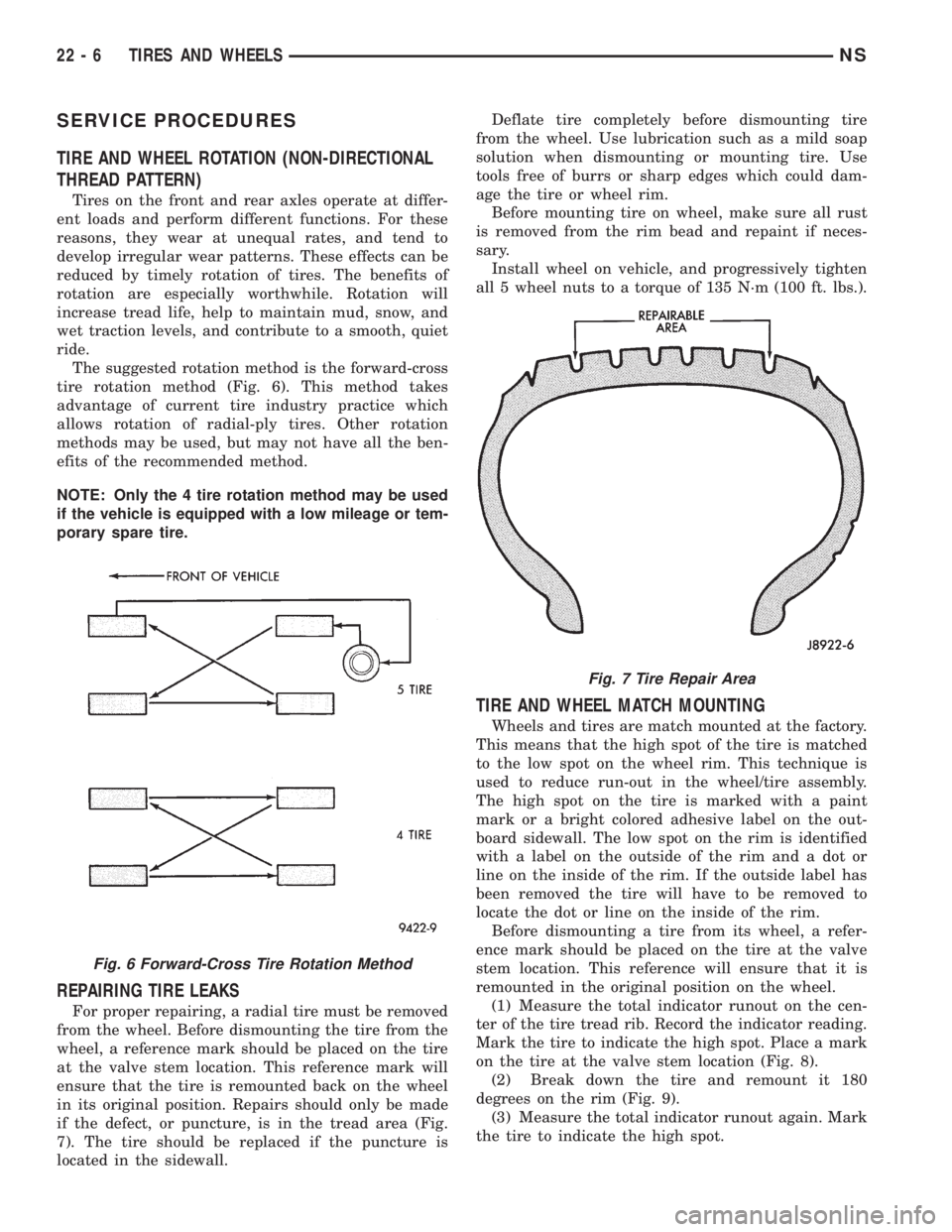
The suggested rotation method is the forward-cross
tire rotation method (Fig. 6). This method takes
advantage of current tire industry practice which
allows rotation of radial-ply tires. Other rotation
methods may be used, but may not have all the ben-
efits of the recommended method.
NOTE: Only the 4 tire rotation method may be used
if the vehicle is equipped with a low mileage or tem-
porary spare tire.
REPAIRING TIRE LEAKS
For proper repairing, a radial tire must be removed
from the wheel. Before dismounting the tire from the
wheel, a reference mark should be placed on the tire
at the valve stem location. This reference mark will
ensure that the tire is remounted back on the wheel
in its original position. Repairs should only be made
if the defect, or puncture, is in the tread area (Fig.
7). The tire should be replaced if the puncture is
located in the sidewall.Deflate tire completely before dismounting tire
from the wheel. Use lubrication such as a mild soap
solution when dismounting or mounting tire. Use
tools free of burrs or sharp edges which could dam-
age the tire or wheel rim.
Before mounting tire on wheel, make sure all rust
is removed from the rim bead and repaint if neces-
sary.
Install wheel on vehicle, and progressively tighten
all 5 wheel nuts to a torque of 135 N´m (100 ft. lbs.).
TIRE AND WHEEL MATCH MOUNTING
Wheels and tires are match mounted at the factory.
This means that the high spot of the tire is matched
to the low spot on the wheel rim. This technique is
used to reduce run-out in the wheel/tire assembly.
The high spot on the tire is marked with a paint
mark or a bright colored adhesive label on the out-
board sidewall. The low spot on the rim is identified
with a label on the outside of the rim and a dot or
line on the inside of the rim. If the outside label has
been removed the tire will have to be removed to
locate the dot or line on the inside of the rim.
Before dismounting a tire from its wheel, a refer-
ence mark should be placed on the tire at the valve
stem location. This reference will ensure that it is
remounted in the original position on the wheel.
(1) Measure the total indicator runout on the cen-
ter of the tire tread rib. Record the indicator reading.
Mark the tire to indicate the high spot. Place a mark
on the tire at the valve stem location (Fig. 8).
(2) Break down the tire and remount it 180
degrees on the rim (Fig. 9).
(3) Measure the total indicator runout again. Mark
the tire to indicate the high spot.
Fig. 6 Forward-Cross Tire Rotation Method
Fig. 7 Tire Repair Area
22 - 6 TIRES AND WHEELSNS