1996 CHRYSLER VOYAGER wheel torque
[x] Cancel search: wheel torquePage 1728 of 1938
WARNING: REPLACEMENT WITH USED WHEELS
IS NOT RECOMMENDED. THE SERVICE HISTORY
OF THE RIM MAY HAVE INCLUDED SEVERE TREAT-
MENT OR VERY HIGH MILEAGE. THE RIM COULD
FAIL WITHOUT WARNING.
TIRE AND WHEEL RUNOUT
NOTE: Runout should always be measured off the
vehicle and on a suitable balance machine.
Radial run out is the difference between the high
and low points on the outer edge of the tire or wheel.
Lateral run out is the total side±to±side wobble of
the tire or wheel.
Radial run out of more than 0.762 mm (.030 inch)
measured at the center line of the tread may cause
the vehicle to shake.
Lateral run out of more than 0.762 mm (.030 inch)
measured at the side of the tire as close to the tread
as possible may cause the vehicle to shake.
Sometimes radial run out can be reduced by relo-
cating the wheel and tire on the wheel studs (See
Method 1). If this does not reduce run out to an
acceptable level, the tire can be rotated on the wheel.
(See Method 2).
METHOD 1 (RELOCATE WHEEL ON HUB)
Check accuracy of the wheel mounting surface;
adjust wheel bearings.
Drive vehicle a short distance to eliminate tire flat
spotting from a parked position.
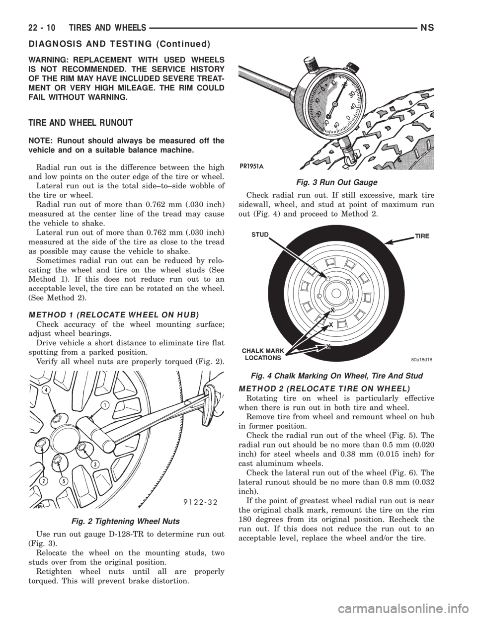
Verify all wheel nuts are properly torqued (Fig. 2).
Use run out gauge D-128-TR to determine run out
(Fig. 3).
Relocate the wheel on the mounting studs, two
studs over from the original position.
Retighten wheel nuts until all are properly
torqued. This will prevent brake distortion.Check radial run out. If still excessive, mark tire
sidewall, wheel, and stud at point of maximum run
out (Fig. 4) and proceed to Method 2.
METHOD 2 (RELOCATE TIRE ON WHEEL)
Rotating tire on wheel is particularly effective
when there is run out in both tire and wheel.
Remove tire from wheel and remount wheel on hub
in former position.
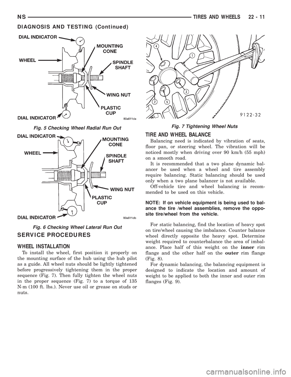
Check the radial run out of the wheel (Fig. 5). The
radial run out should be no more than 0.5 mm (0.020
inch) for steel wheels and 0.38 mm (0.015 inch) for
cast aluminum wheels.
Check the lateral run out of the wheel (Fig. 6). The
lateral runout should be no more than 0.8 mm (0.032
inch).
If the point of greatest wheel radial run out is near
the original chalk mark, remount the tire on the rim
180 degrees from its original position. Recheck the
run out. If this does not reduce the run out to an
acceptable level, replace the wheel and/or the tire.
Fig. 2 Tightening Wheel Nuts
Fig. 3 Run Out Gauge
Fig. 4 Chalk Marking On Wheel, Tire And Stud
22 - 10 TIRES AND WHEELSNS
DIAGNOSIS AND TESTING (Continued)
Page 1729 of 1938
SERVICE PROCEDURES
WHEEL INSTALLATION
To install the wheel, first position it properly on
the mounting surface of the hub using the hub pilot
as a guide. All wheel nuts should be lightly tightened
before progressively tightening them in the proper
sequence (Fig. 7). Then fully tighten the wheel nuts
in the proper sequence (Fig. 7) to a torque of 135
N´m (100 ft. lbs.). Never use oil or grease on studs or
nuts.
TIRE AND WHEEL BALANCE
Balancing need is indicated by vibration of seats,
floor pan, or steering wheel. The vibration will be
noticed mostly when driving over 90 km/h (55 mph)
on a smooth road.
It is recommended that a two plane dynamic bal-
ancer be used when a wheel and tire assembly
require balancing. Static balancing should be used
only when a two plane balancer is not available.
Off-vehicle tire and wheel balancing is recom-
mended to be used on this vehicle.
NOTE: If on vehicle equipment is being used to bal-
ance the tire /wheel assemblies, remove the oppo-
site tire/wheel from the vehicle.
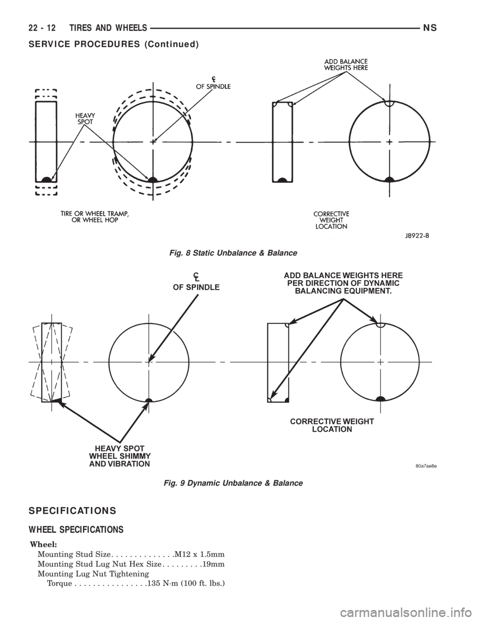
For static balancing, find the location of heavy spot
on tire/wheel causing the imbalance. Counter balance
wheel directly opposite the heavy spot. Determine
weight required to counterbalance the area of imbal-
ance. Place half of this weight on theinnerrim
flange and the other half on theouterrim flange
(Fig. 8).
For dynamic balancing, the balancing equipment is
designed to indicate the location and amount of
weight to be applied to both the inner and outer rim
flanges (Fig. 9).
Fig. 5 Checking Wheel Radial Run Out
Fig. 6 Checking Wheel Lateral Run Out
Fig. 7 Tightening Wheel Nuts
NSTIRES AND WHEELS 22 - 11
DIAGNOSIS AND TESTING (Continued)
Page 1730 of 1938
SPECIFICATIONS
WHEEL SPECIFICATIONS
Wheel:
Mounting Stud Size..............M12 x 1.5mm
Mounting Stud Lug Nut Hex Size.........19mm
Mounting Lug Nut Tightening
Torque................135 N´m (100 ft. lbs.)
Fig. 8 Static Unbalance & Balance
Fig. 9 Dynamic Unbalance & Balance
22 - 12 TIRES AND WHEELSNS
SERVICE PROCEDURES (Continued)
Page 1775 of 1938
(18) Pass front seat belt and turning loop through
slot in quarter trim panel on three door vehicle.
(19) Pass first rear seat belt through slot in quar-
ter trim panel.
(20) Pass second rear seat belt, if equipped,
through slot in quarter trim panel on long wheel
base vehicle.
(21) Remove quarter trim panel from vehicle.
INSTALLATION
(1) Position quarter trim panel on vehicle.
(2) Pass second rear seat belt, if equipped, through
slot in quarter trim panel on long wheel base vehicle.
(3) Pass first rear seat belt through slot in quarter
trim panel.
(4) Pass front seat belt through slot in quarter
trim panel on three door vehicle.
(5) Connect wire connector into accessory power
outlet, if equipped.
(6) Align locating pins on backside of trim panel to
mating holes in inner panels.
(7) Position quarter trim panel on inner quarter
panel.
(8) Install screws to hold top of trim panel to inner
sheet metal between B-pillar and C-pillar on three
door vehicle.(9) Install screws to hold rear edge of quarter trim
to attaching bracket or inner quarter panel.
(10) Install screws to hold quarter trim to inner
quarter panel in bolster area.
(11) Install screws to hold quarter trim to inner
quarter panel in B-pillar area on three door vehicle.
(12) Install left front seat belt opening bezel into
quarter trim on three door vehicle.
(13) Install second rear seat belts anchor on long
wheel base vehicle. Tighten all seat belt bolts to 39
N´m (28 in. lbs.) torque.
(14) Install first rear seat belt anchor.
(15) Install left D-pillar trim panel.
(16) Install C-pillar trim panel.
(17) Install upper left B-pillar trim on three door
vehicle.
(18) Install left quarter trim bolster.
(19) Install front door sill plate on three door vehi-
cle.
(20) Install sliding door sill plate on four door
vehicle.
(21) Install second rear seat, if equipped.
(22) Install first rear seat.
(23) Connect the battery negative cable.
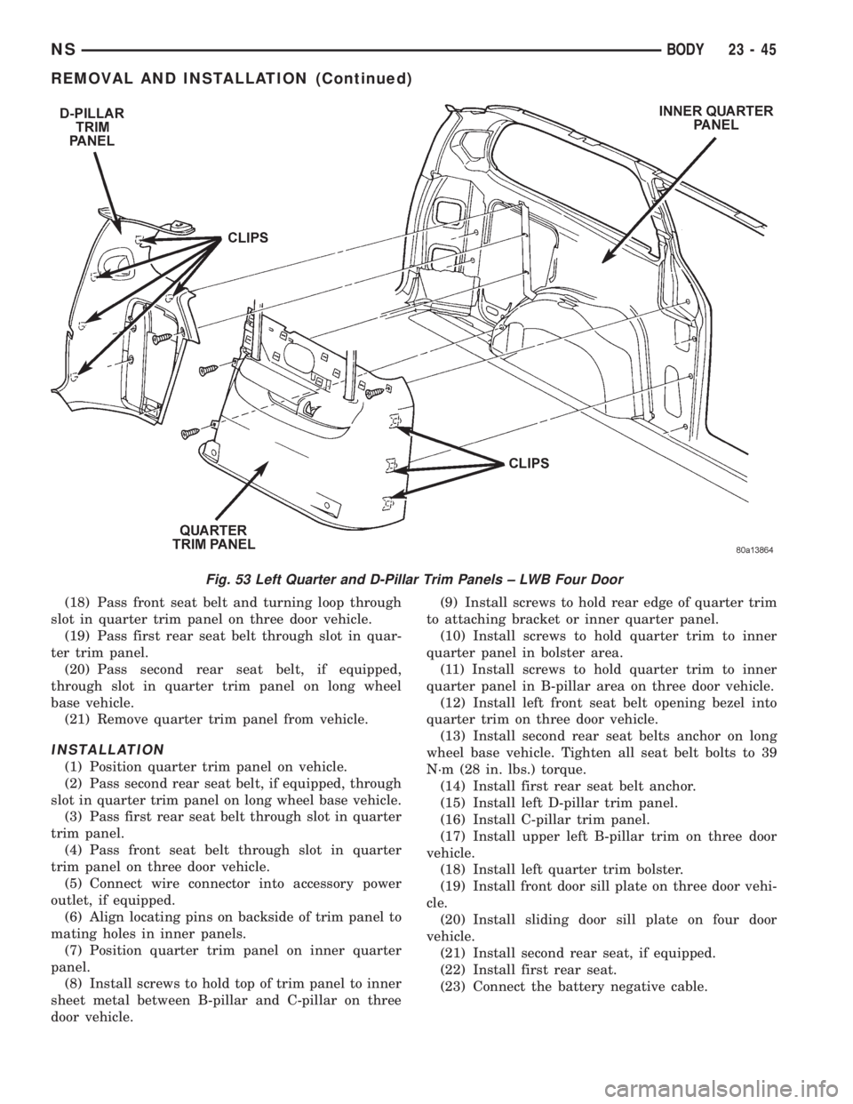
Fig. 53 Left Quarter and D-Pillar Trim Panels ± LWB Four Door
NSBODY 23 - 45
REMOVAL AND INSTALLATION (Continued)
Page 1785 of 1938
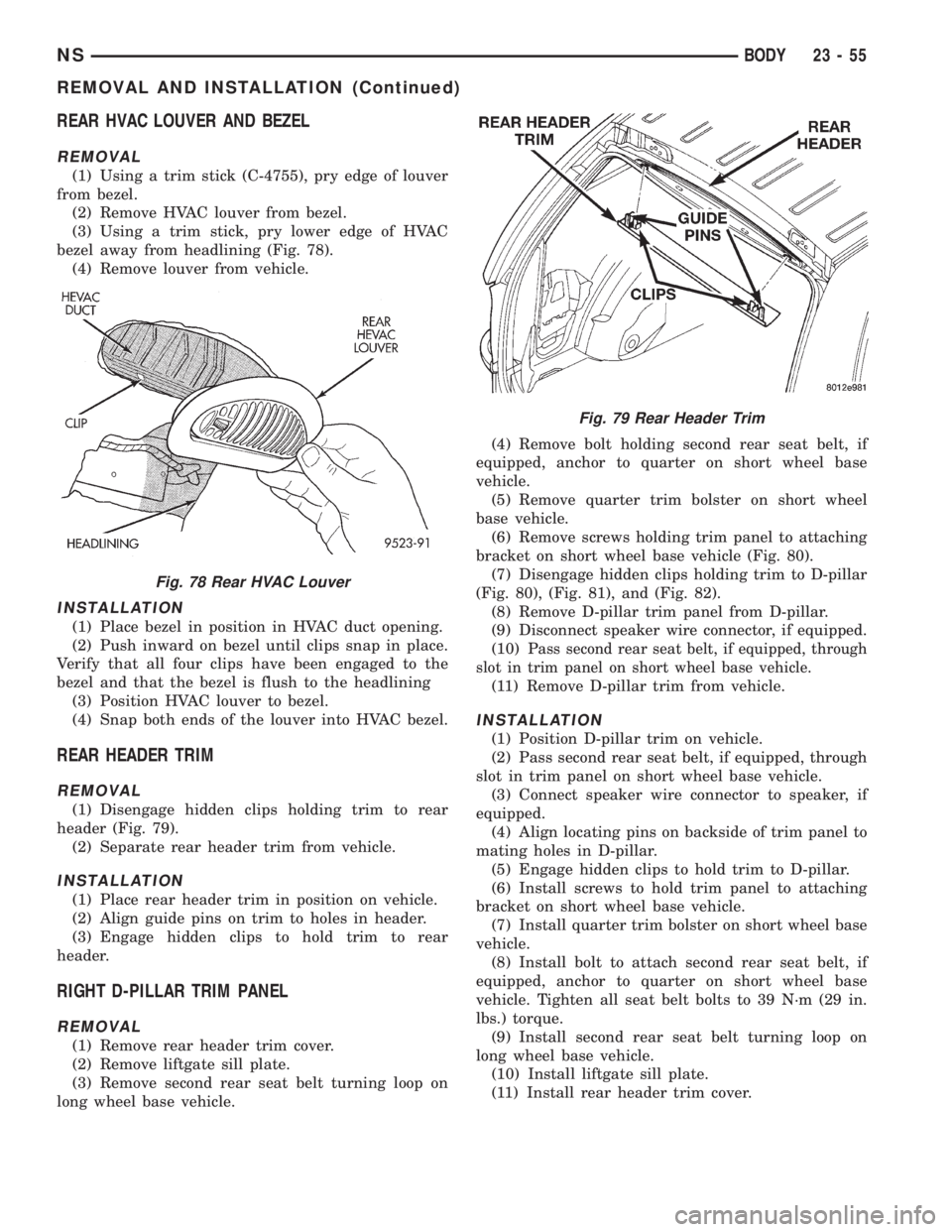
REAR HVAC LOUVER AND BEZEL
REMOVAL
(1) Using a trim stick (C-4755), pry edge of louver
from bezel.
(2) Remove HVAC louver from bezel.
(3) Using a trim stick, pry lower edge of HVAC
bezel away from headlining (Fig. 78).
(4) Remove louver from vehicle.
INSTALLATION
(1) Place bezel in position in HVAC duct opening.
(2) Push inward on bezel until clips snap in place.
Verify that all four clips have been engaged to the
bezel and that the bezel is flush to the headlining
(3) Position HVAC louver to bezel.
(4) Snap both ends of the louver into HVAC bezel.
REAR HEADER TRIM
REMOVAL
(1) Disengage hidden clips holding trim to rear
header (Fig. 79).
(2) Separate rear header trim from vehicle.
INSTALLATION
(1) Place rear header trim in position on vehicle.
(2) Align guide pins on trim to holes in header.
(3) Engage hidden clips to hold trim to rear
header.
RIGHT D-PILLAR TRIM PANEL
REMOVAL
(1) Remove rear header trim cover.
(2) Remove liftgate sill plate.
(3) Remove second rear seat belt turning loop on
long wheel base vehicle.(4) Remove bolt holding second rear seat belt, if
equipped, anchor to quarter on short wheel base
vehicle.
(5) Remove quarter trim bolster on short wheel
base vehicle.
(6) Remove screws holding trim panel to attaching
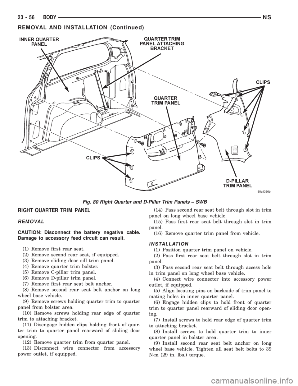
bracket on short wheel base vehicle (Fig. 80).
(7) Disengage hidden clips holding trim to D-pillar
(Fig. 80), (Fig. 81), and (Fig. 82).
(8) Remove D-pillar trim panel from D-pillar.
(9) Disconnect speaker wire connector, if equipped.
(10) P
ass second rear seat belt, if equipped, through
slot in trim panel on short wheel base vehicle.
(11) Remove D-pillar trim from vehicle.
INSTALLATION
(1) Position D-pillar trim on vehicle.
(2) Pass second rear seat belt, if equipped, through
slot in trim panel on short wheel base vehicle.
(3) Connect speaker wire connector to speaker, if
equipped.
(4) Align locating pins on backside of trim panel to
mating holes in D-pillar.
(5) Engage hidden clips to hold trim to D-pillar.
(6) Install screws to hold trim panel to attaching
bracket on short wheel base vehicle.
(7) Install quarter trim bolster on short wheel base
vehicle.
(8) Install bolt to attach second rear seat belt, if
equipped, anchor to quarter on short wheel base
vehicle. Tighten all seat belt bolts to 39 N´m (29 in.
lbs.) torque.
(9) Install second rear seat belt turning loop on
long wheel base vehicle.
(10) Install liftgate sill plate.
(11) Install rear header trim cover.
Fig. 78 Rear HVAC Louver
Fig. 79 Rear Header Trim
NSBODY 23 - 55
REMOVAL AND INSTALLATION (Continued)
Page 1786 of 1938
RIGHT QUARTER TRIM PANEL
REMOVAL
CAUTION: Disconnect the battery negative cable.
Damage to accessory feed circuit can result.
(1) Remove first rear seat.
(2) Remove second rear seat, if equipped.
(3) Remove sliding door sill trim panel.
(4) Remove quarter trim bolster.
(5) Remove C-pillar trim panel.
(6) Remove D-pillar trim panel.
(7) Remove first rear seat belt anchor.
(8) Remove second rear seat belt anchor on long
wheel base vehicle.
(9) Remove screws holding quarter trim to quarter
panel from bolster area.
(10) Remove screws holding rear edge of quarter
trim to attaching bracket.
(11) Disengage hidden clips holding front of quar-
ter trim to quarter panel rearward of sliding door
opening.
(12) Remove quarter trim from quarter panel.
(13) Disconnect wire connector from accessory
power outlet, if equipped.(14) Pass second rear seat belt through slot in trim
panel on long wheel base vehicle.
(15) Pass first rear seat belt through slot in trim
panel.
(16) Remove quarter trim panel from vehicle.
INSTALLATION
(1) Position quarter trim panel on vehicle.
(2) Pass first rear seat belt through slot in trim
panel.
(3) Pass second rear seat belt through access hole
in trim panel on long wheel base vehicle.
(4) Connect wire connector into accessory power
outlet, if equipped.
(5) Align locating pins on backside of trim panel to
mating holes in inner quarter panel.
(6) Engage hidden clips to hold front of quarter
trim to quarter panel rearward of sliding door open-
ing.
(7) Install screws to hold rear edge of quarter trim
to attaching bracket.
(8) Install screws to hold quarter trim to inner
quarter panel in bolster area.
(9) Install second rear seat belt anchor on long
wheel base vehicle. Tighten all seat belt bolts to 39
N´m (29 in. lbs.) torque.
Fig. 80 Right Quarter and D-Pillar Trim Panels ± SWB
23 - 56 BODYNS
REMOVAL AND INSTALLATION (Continued)
Page 1791 of 1938
SEAT BELT LEFT FIRST REAR OUTBOARD ± LWB
THREE DOOR
REMOVAL
(1) Remove first and second rear seats. Refer to
Owner's manual for proper procedures.
(2) Remove shoulder harness height adjuster knob
by pulling it straight away from adjuster.
(3) Slide floor anchor cover from over the anchor
bolt.
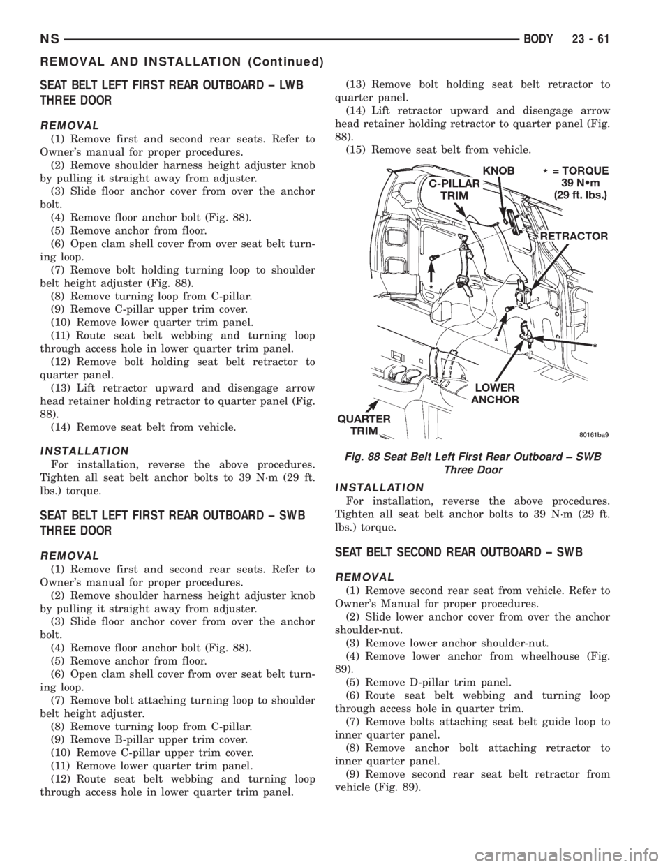
(4) Remove floor anchor bolt (Fig. 88).
(5) Remove anchor from floor.
(6) Open clam shell cover from over seat belt turn-
ing loop.
(7) Remove bolt holding turning loop to shoulder
belt height adjuster (Fig. 88).
(8) Remove turning loop from C-pillar.
(9) Remove C-pillar upper trim cover.
(10) Remove lower quarter trim panel.
(11) Route seat belt webbing and turning loop
through access hole in lower quarter trim panel.
(12) Remove bolt holding seat belt retractor to
quarter panel.
(13) Lift retractor upward and disengage arrow
head retainer holding retractor to quarter panel (Fig.
88).
(14) Remove seat belt from vehicle.
INSTALLATION
For installation, reverse the above procedures.
Tighten all seat belt anchor bolts to 39 N´m (29 ft.
lbs.) torque.
SEAT BELT LEFT FIRST REAR OUTBOARD ± SWB
THREE DOOR
REMOVAL
(1) Remove first and second rear seats. Refer to
Owner's manual for proper procedures.
(2) Remove shoulder harness height adjuster knob
by pulling it straight away from adjuster.
(3) Slide floor anchor cover from over the anchor
bolt.
(4) Remove floor anchor bolt (Fig. 88).
(5) Remove anchor from floor.
(6) Open clam shell cover from over seat belt turn-
ing loop.
(7) Remove bolt attaching turning loop to shoulder
belt height adjuster.
(8) Remove turning loop from C-pillar.
(9) Remove B-pillar upper trim cover.
(10) Remove C-pillar upper trim cover.
(11) Remove lower quarter trim panel.
(12) Route seat belt webbing and turning loop
through access hole in lower quarter trim panel.(13) Remove bolt holding seat belt retractor to
quarter panel.
(14) Lift retractor upward and disengage arrow
head retainer holding retractor to quarter panel (Fig.
88).
(15) Remove seat belt from vehicle.
INSTALLATION
For installation, reverse the above procedures.
Tighten all seat belt anchor bolts to 39 N´m (29 ft.
lbs.) torque.
SEAT BELT SECOND REAR OUTBOARD ± SWB
REMOVAL
(1) Remove second rear seat from vehicle. Refer to
Owner's Manual for proper procedures.
(2) Slide lower anchor cover from over the anchor
shoulder-nut.
(3) Remove lower anchor shoulder-nut.
(4) Remove lower anchor from wheelhouse (Fig.
89).
(5) Remove D-pillar trim panel.
(6) Route seat belt webbing and turning loop
through access hole in quarter trim.
(7) Remove bolts attaching seat belt guide loop to
inner quarter panel.
(8) Remove anchor bolt attaching retractor to
inner quarter panel.
(9) Remove second rear seat belt retractor from
vehicle (Fig. 89).
Fig. 88 Seat Belt Left First Rear Outboard ± SWB
Three Door
NSBODY 23 - 61
REMOVAL AND INSTALLATION (Continued)
Page 1792 of 1938
INSTALLATION
For installation, reverse the above procedures.
Tighten all seat belts to 39 N´m (29 ft. lbs.) torque.
SEAT BELT SECOND RIGHT REAR OUTBOARD ±
LW B
REMOVAL
(1) Remove second rear seat from vehicle. Refer to
Owner's Manual for proper procedures.
(2) Slide lower anchor cover from over the anchor
shoulder-nut.
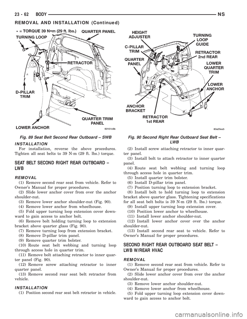
(3) Remove lower anchor shoulder-nut (Fig. 90).
(4) Remove lower anchor from wheelhouse.
(5) Fold upper turning loop extension cover down-
ward to gain access to anchor bolt.
(6) Remove bolt holding turning loop to extension
bracket above quarter glass (Fig. 90).
(7) Remove turning loop from extension bracket.
(8) Remove D-pillar trim panel.
(9) Remove quarter trim bolster.
(10) Route seat belt webbing and turning loop
through access hole in quarter trim.
(11) Remove bolt attaching retractor to inner quar-
ter panel (Fig. 90).
(12) Remove screw attaching retractor to inner
quarter panel.
(13) Remove second rear seat belt retractor from
vehicle.
INSTALLATION
(1) Position second rear seat belt retractor in vehicle.
(2) Install screw attaching retractor to inner quar-
ter panel.
(3) Install bolt to attach retractor to inner quarter
panel.
(4) Route seat belt webbing and turning loop
through access hole in quarter trim.
(5) Install quarter trim bolster.
(6) Install D-pillar trim panel.
(7) Position turning loop to extension bracket.
(8) Install bolt to hold turning loop to extension
bracket above quarter glass. Tightening specifications
for all seat belt bolts is 39 N´m (29 ft. lbs.) torque.
(9) Install upper turning loop extension cover.
(10) Position lower anchor to wheelhouse.
(11) Install lower anchor shoulder-nut.
(12) Install lower anchor cover over the anchor
shoulder-nut.
(13) Install second rear seat to vehicle. Refer to
Owner's Manual for proper procedures.
SECOND RIGHT REAR OUTBOARD SEAT BELT ±
LWB W/REAR HVAC
REMOVAL
(1) Remove second rear seat from vehicle. Refer to
Owner's Manual for proper procedures.
(2) Slide lower anchor cover from over the anchor
shoulder-nut.
(3) Remove lower anchor shoulder-nut.
(4) Remove lower anchor from wheelhouse.
(5) Fold upper turning loop extension cover down-
ward to gain access to anchor bolt.
Fig. 89 Seat Belt Second Rear Outboard ± SWBFig. 90 Second Right Rear Outboard Seat Belt ±
LW B
23 - 62 BODYNS
REMOVAL AND INSTALLATION (Continued)