Page 1664 of 1938
(3) Remove gearshift cables. Refer to Gearshift
Cable Removal in this section.
(4) Remove retaining nuts at the base of the gear-
shift mechanism. Remove shifter.
INSTALLATION
(1) For installation, reverse removal procedure.
GEARSHIFT MECHANISM REPLACEMENTÐRHD
VEHICLES
REMOVAL
(1) Remove shifter knob and boot. Refer to Shifter
Knob And Boot Removal procedure in this section.
(2) Remove console assembly. Refer to Console
Removal procedure in Group 23 in this manual.
Fig. 15 Gearshift Cables
Fig. 16 Crossover Lever Shift CableFig. 17 Selector Lever Shift Cable
21 - 8 A±598 MANUAL TRANSAXLENS/GS
REMOVAL AND INSTALLATION (Continued)
Page 1701 of 1938

(3) Install the synchro springs into the synchro
struts.
(4) Line up stop ring tang over the struts in the
hub. Install stop rings. Center the struts by pushing
on both stop rings.
(5) Install the outer cones (dual-cone synchronizer)
into the synchronizer stop rings.
(6) Install the inner cones (dual-cone synchronizer)
into the outer cones.
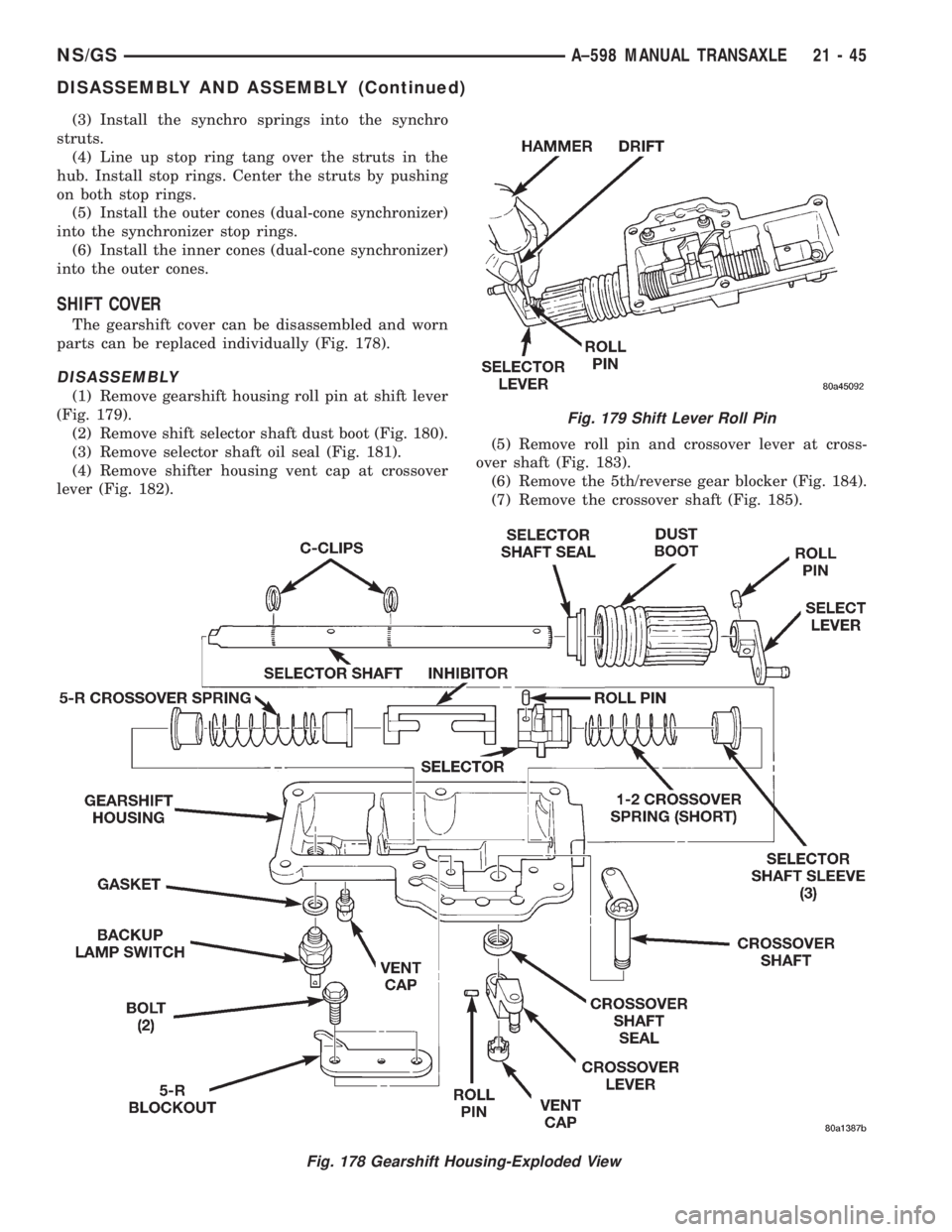
SHIFT COVER
The gearshift cover can be disassembled and worn
parts can be replaced individually (Fig. 178).
DISASSEMBLY
(1) Remove gearshift housing roll pin at shift lever
(Fig. 179).
(2) Remove shift selector shaft dust boot (Fig. 180).
(3) Remove selector shaft oil seal (Fig. 181).
(4) Remove shifter housing vent cap at crossover
lever (Fig. 182).(5) Remove roll pin and crossover lever at cross-
over shaft (Fig. 183).
(6) Remove the 5th/reverse gear blocker (Fig. 184).
(7) Remove the crossover shaft (Fig. 185).
Fig. 178 Gearshift Housing-Exploded View
Fig. 179 Shift Lever Roll Pin
NS/GSA±598 MANUAL TRANSAXLE 21 - 45
DISASSEMBLY AND ASSEMBLY (Continued)
Page 1702 of 1938
(8) Remove selector shaft inner C-clip (Fig. 186).
(9) Remove selector shaft outer C-clip (Fig. 187).
Fig. 180 Dust Boot
Fig. 181 Oil Seal
Fig. 182 Vent Cap
Fig. 183 Crossover Lever and Roll Pin
Fig. 184 5th/Reverse Blocker
Fig. 185 Crossover Shaft
21 - 46 A±598 MANUAL TRANSAXLENS/GS
DISASSEMBLY AND ASSEMBLY (Continued)
Page 1704 of 1938

NOTE: The C-Clip grooves in the selector shaft will
damage the oil seal. Install oil seal after selector
shaft is installed. Always use a new oil seal when
selector shaft is removed.
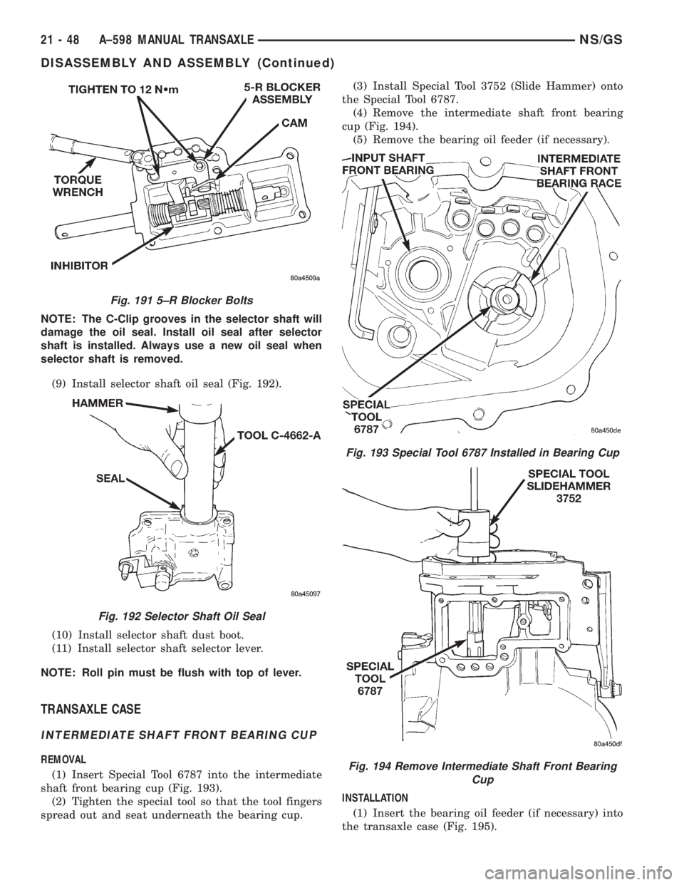
(9) Install selector shaft oil seal (Fig. 192).
(10) Install selector shaft dust boot.
(11) Install selector shaft selector lever.
NOTE: Roll pin must be flush with top of lever.
TRANSAXLE CASE
INTERMEDIATE SHAFT FRONT BEARING CUP
REMOVAL
(1) Insert Special Tool 6787 into the intermediate
shaft front bearing cup (Fig. 193).
(2) Tighten the special tool so that the tool fingers
spread out and seat underneath the bearing cup.(3) Install Special Tool 3752 (Slide Hammer) onto
the Special Tool 6787.
(4) Remove the intermediate shaft front bearing
cup (Fig. 194).
(5) Remove the bearing oil feeder (if necessary).
INSTALLATION
(1) Insert the bearing oil feeder (if necessary) into
the transaxle case (Fig. 195).
Fig. 191 5±R Blocker Bolts
Fig. 192 Selector Shaft Oil Seal
Fig. 193 Special Tool 6787 Installed in Bearing Cup
Fig. 194 Remove Intermediate Shaft Front Bearing
Cup
21 - 48 A±598 MANUAL TRANSAXLENS/GS
DISASSEMBLY AND ASSEMBLY (Continued)
Page 1709 of 1938
be screwed into the housing. This operation locks the
selector shaft in the 3-4 neutral position.
(5) Remove gearshift knob (Fig. 213).
(6) Remove gearshift boot (Fig. 214).
(7) Remove gearshift console screws and remove
the console (Fig. 215).
(8) Loosen crossover cable adjustment screw.
(9) Verify gearshift mechanism is in the neutral
position.CAUTION: Be sure crossover bellcrank does NOT
move when tightening adjusting screw.
Fig. 210 Gearshift Mechanism
Fig. 211 Auxiliary Vent Removal
Fig. 212 Lock Pin Installation
NS/GSA±598 MANUAL TRANSAXLE 21 - 53
ADJUSTMENTS (Continued)
Page 1710 of 1938
(10) Tighten crossover cable adjuster to 8 N´m (70
in. lbs.) (Fig. 216).CAUTION: Proper torque to the crossover cable
adjusting screw is very important.
(11) Remove lock pin from gearshift housing. Rein-
stall auxiliary vent in gear shift housing (Fig. 217).
Tighten auxiliary vent to 8 N´m (70 in. lbs.).
(12) Check for shift into first and reverse.
(13) Gearshift mechanism and cables are now
functioning properly.
(14) Install gearshift console.
(15) Install gearshift boot.
(16) Install gearshift knob.
(17) Stow gearshift lock pin in glove packet.
Fig. 213 Gearshift Knob
Fig. 214 Gearshift Boot
Fig. 215 Gearshift Console
Fig. 216 Crossover Cable Adjustment
Fig. 217 Auxiliary Vent Installation
21 - 54 A±598 MANUAL TRANSAXLENS/GS
ADJUSTMENTS (Continued)
Page 1711 of 1938

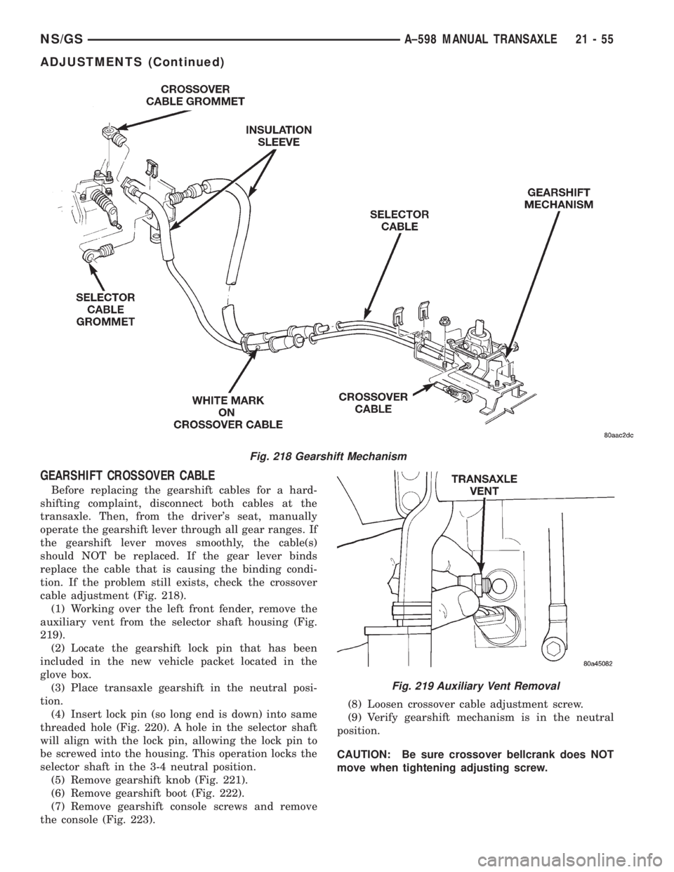
GEARSHIFT CROSSOVER CABLE
Before replacing the gearshift cables for a hard-
shifting complaint, disconnect both cables at the
transaxle. Then, from the driver's seat, manually
operate the gearshift lever through all gear ranges. If
the gearshift lever moves smoothly, the cable(s)
should NOT be replaced. If the gear lever binds
replace the cable that is causing the binding condi-
tion. If the problem still exists, check the crossover
cable adjustment (Fig. 218).
(1) Working over the left front fender, remove the
auxiliary vent from the selector shaft housing (Fig.
219).
(2) Locate the gearshift lock pin that has been
included in the new vehicle packet located in the
glove box.
(3) Place transaxle gearshift in the neutral posi-
tion.
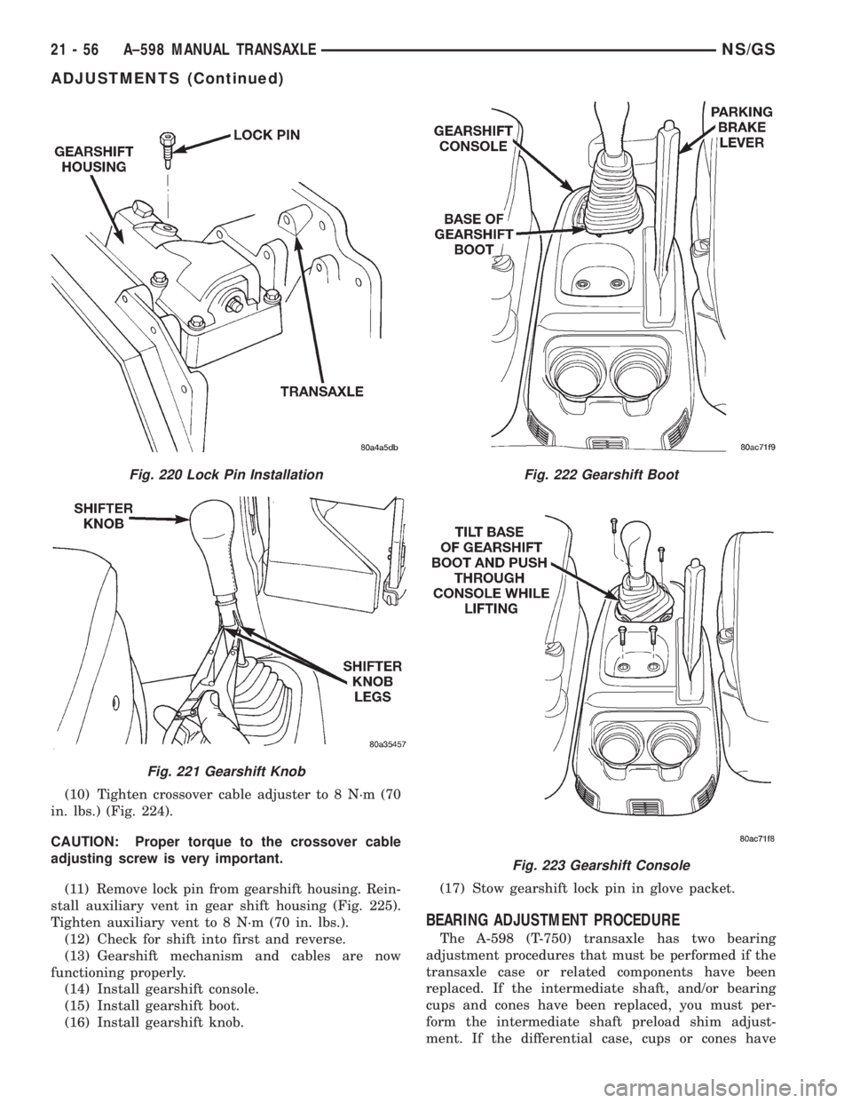
(4) Insert lock pin (so long end is down) into same
threaded hole (Fig. 220). A hole in the selector shaft
will align with the lock pin, allowing the lock pin to
be screwed into the housing. This operation locks the
selector shaft in the 3-4 neutral position.
(5) Remove gearshift knob (Fig. 221).
(6) Remove gearshift boot (Fig. 222).
(7) Remove gearshift console screws and remove
the console (Fig. 223).(8) Loosen crossover cable adjustment screw.
(9) Verify gearshift mechanism is in the neutral
position.
CAUTION: Be sure crossover bellcrank does NOT
move when tightening adjusting screw.
Fig. 218 Gearshift Mechanism
Fig. 219 Auxiliary Vent Removal
NS/GSA±598 MANUAL TRANSAXLE 21 - 55
ADJUSTMENTS (Continued)
Page 1712 of 1938

(10) Tighten crossover cable adjuster to 8 N´m (70
in. lbs.) (Fig. 224).
CAUTION: Proper torque to the crossover cable
adjusting screw is very important.
(11) Remove lock pin from gearshift housing. Rein-
stall auxiliary vent in gear shift housing (Fig. 225).
Tighten auxiliary vent to 8 N´m (70 in. lbs.).
(12) Check for shift into first and reverse.
(13) Gearshift mechanism and cables are now
functioning properly.
(14) Install gearshift console.
(15) Install gearshift boot.
(16) Install gearshift knob.(17) Stow gearshift lock pin in glove packet.
BEARING ADJUSTMENT PROCEDURE
The A-598 (T-750) transaxle has two bearing
adjustment procedures that must be performed if the
transaxle case or related components have been
replaced. If the intermediate shaft, and/or bearing
cups and cones have been replaced, you must per-
form the intermediate shaft preload shim adjust-
ment. If the differential case, cups or cones have
Fig. 220 Lock Pin Installation
Fig. 221 Gearshift Knob
Fig. 222 Gearshift Boot
Fig. 223 Gearshift Console
21 - 56 A±598 MANUAL TRANSAXLENS/GS
ADJUSTMENTS (Continued)