1996 CHRYSLER VOYAGER boot
[x] Cancel search: bootPage 327 of 1938

CAUTION: Never coat the inside of spark plug
boots with silicone grease. Some types of silicone
grease can damage the ignition cable conductor.
SPARK PLUG CABLES #3 AND #5
REMOVAL
(1) Remove the resonator.
(2) Grasp the spark plug boot/heat shield as close
as possible to the spark plug.Twist the boot
slightly to break its seal with the plug and pull
straight back. Do not use pliers, pull on the
ignition cable, or pull the spark plug boot at an
angle.This could damage the spark plug insulator,
terminal, or the cable insulation. Wipe spark plug
insulator clean with a dry cloth before installation.
(3) Remove the cable from the retaining bracket.
Make sure that they are also detached from the rear
retaining clip mounted on the rear of the intake
manifold.
INSTALLATION
(1) When installing the spark plug cables, make
sure the coil and spark plug insulator and terminals
are fully seated. Aclick sound should be heard or
terminal engagement is felt when the terminals
are properly attached.
(2) Install the cable into the retaining bracket.
Make sure that they are also attached to the rear
retaining clip mounted on the rear of the intake
manifold.
(3) Install the resonator.
SPARK PLUG CABLE #1
REMOVAL
(1) Remove the accessory drive belt, refer to Group
7, Cooling.
(2) Remove the four bolts from the upper half of
the generator bracket.
(3) Push the Generator rearward.
(4) Grasp the spark plug boot/shield assembly as
close as possible to the spark plug.Twist the boot
slightly to break its seal with the plug and pull
straight back. Do not use pliers, pull on the
ignition cable, or pull the spark plug boot at an
angle.This could damage the spark plug insulator,
terminal, or the cable insulation. Wipe spark plug
insulator clean with a dry cloth before installation.
(5) Remove the cable from the retaining bracket.
INSTALLATION
(1) When installing the spark plug cables, make
sure the coil and spark plug insulator and terminals
are fully seated. Aclick sound should be heard orterminal engagement is felt when the terminals
are properly attached.
(2) Rotate Generator back into place.
(3) Install upper Generator bracket with the four
bolts.
(4) Install the accessory drive belt, refer to Group
7, Cooling.
SPARK PLUG SERVICEÐ3.3/3.8L ENGINES
WARNING: The ignition cables should not be
removed while the engine is hot. This could cause
server injury/burns and can cause damage to the
ignition cables.
Use extreme care when removing and installing
the spark plug cables.
The spark plug boot heat shield needs to be
installed correctly on the boot before being installed
on the engine (Fig. 1). If it is not installed correctly
engine misfire would occur.
Do not use pliers to pull the boot/heat shield
assembly from the spark plugs. This will damage the
shield assembly.
SPARK PLUG #3 AND #5
REMOVAL
(1) Remove the resonator.
(2) Remove intake strut to cylinder head bolt at
cylinder head.
(3) Loosen bolt for intake strut at intake.
(4) Swing strut away.
(5) Grasp the spark plug boot/shield assembly as
close as possible to the spark plug.Twist the boot/
shield assembly slightly to break the seal with
the plug and pull straight out. Do not use pli-
ers, pull on the ignition cable, or pull the spark
plug boot at an angle.This could damage the
spark plug insulator, terminal, heat shield or the
insulation. Wipe spark plug insulator clean with a
dry cloth before installation.
(6) Remove spark plug
INSTALLATION
(1) Install spark plug and tighten to 28 N´m (20 ft.
lbs.).
(2) When installing the spark plug cables, make
sure spark plug insulator and terminals are fully
seated. Aclick sound should be heard or felt
when the terminals are properly attached.
(3) Install the cable into the retaining bracket.
Make sure that they are also attached to the rear
retaining clip mounted on the rear of the intake
manifold.
(4) Swing strut back into place.
NSIGNITION SYSTEM 8D - 29
REMOVAL AND INSTALLATION (Continued)
Page 328 of 1938

(5) Install intake strut bolt to cylinder head at cyl-
inder head.
(6) Tighten bolt to intake strut at intake.
(7) Tighten bolt at cylinder head.
(8) Install the resonator.
SPARK PLUG #1
REMOVAL
(1) Remove the accessory drive belt, refer to Group
7, Cooling.
(2) Remove the 4 bolts from the upper half of the
generator bracket.
(3) Push the Generator rearward.
(4) Grasp the spark plug boot/shield assembly as
close as possible to the spark plug.Twist the boot/
shield assembly slightly to break its seal with
the plug and pull straight out. Do not use pli-
ers, pull on the ignition cable, or pull the spark
plug boot at an angle.This could damage the
spark plug insulator, terminal, or the insulation.
Wipe spark plug insulator clean with a dry cloth
before installation.
(5) Remove spark plug
INSTALLATION
(1) Install spark plug and tighten to 28 N´m (20 ft.
lbs.).
(2) When installing the spark plug cables, make
sure the coil or spark plug insulator and terminals
are fully seated. Aclick sound should be heard or
felt when the terminals are properly attached.
(3) Pull Generator back into place.
(4) Install upper Generator bracket with the 4
bolts.
(5) Install the accessory drive belt, refer to Group
7, Cooling.
IGNITION COIL
REMOVAL
(1) Remove spark plug cables from coil (Fig. 2).
Always twist the spark plug boots to break the seal
with the plug and pull straight back on the boot.
(2) Remove ignition coil electrical connector.
(3) Remove ignition coil mounting screws.
(4) Remove ignition coil.
INSTALLATION
(1) Reverse the above procedure for installation.
Tighten mounting screws to 12 N´m (105 in. lbs.)
torque.
(2) Transfer spark plug cables to new coil pack.
The coil pack towers and cables are numbered with
the cylinder identification.
CRANKSHAFT POSITION SENSOR
REMOVAL
(1) Raise and support vehicle.
(2) Disconnect crankshaft position sensor electrical
connector from the wiring harness connector (Fig. 3).
(3) Remove crankshaft position sensor retaining
bolt.
(4) Pull crankshaft position sensor straight up out
of the transaxle housing.
INSTALLATION
NOTE: If the removed sensor is to be reinstalled,
clean off the old spacer on the sensor face. A NEW
SPACER must be attached to the sensor face before
installation. If the sensor is being replaced, confirm
that the paper spacer is attached to the face of the
new sensor (Fig. 4).
(1) Install sensor in transaxle and push sensor
down until contact is made with the drive plate.
Fig. 2 Ignition Coil Removal
Fig. 3 Crankshaft Position Sensor Connector
8D - 30 IGNITION SYSTEMNS
REMOVAL AND INSTALLATION (Continued)
Page 486 of 1938

LAMP BULB SERVICE
INDEX
page page
REMOVAL AND INSTALLATION
CENTER HIGH MOUNTED STOP LAMP
(CHMSL) BULB....................... 12
CITYLIGHT LAMP BULB.................. 9
FOG LAMP BULB........................ 9FRONT TURN SIGNAL LAMP BULB.......... 8
HEADLAMP BULB....................... 8
LICENSE PLATE LAMP BULB............. 12
SIDE REPEATER LAMP BULB............. 10
TAIL LAMP BULB....................... 10
REMOVAL AND INSTALLATION
HEADLAMP BULB
REMOVAL
(1) Release hood latch and open hood.
(2) Remove headlamp module from vehicle.
(3) Remove rubber seal boot (Fig. 1).
(4) Disengage retaining spring clip from headlamp
(Fig. 2).
(5) Pivot spring clip from headlamp bulb removal
path.
(6) Pull headlamp bulb from back of headlamp
(Fig. 3).
INSTALLATION
CAUTION: Do not touch the glass of halogen bulbs
with fingers of other possibly oily surface. Reduced
bulb life will result.
(1) Insert headlamp bulb to headlamp.
(2) Pivot spring clip over headlamp bulb.
(3) Engage retaining spring clip to headlamp.
(4) Install rubber seal boot.(5) Engage wire connector to headlamp bulb base.
(6) Install headlamp module into vehicle
(7) Verify headlamp alignment.
FRONT TURN SIGNAL LAMP BULB
REMOVAL
(1) Remove headlamp module from vehicle
Fig. 1 Rubber Boot Seal
Fig. 2 Headlamp Bulb Spring Clip
Fig. 3 Headlamp Bulb
8L - 8 LAMPSNS/GS
Page 1156 of 1938

CRANKSHAFT DAMPER
REMOVAL
(1) Disconnect negative cable from battery.
(2) Raise vehicle on hoist.
(3) Remove right wheel and inner splash shield.
(4) Remove drive belt. Refer to Group 7, Cooling
System for procedure.
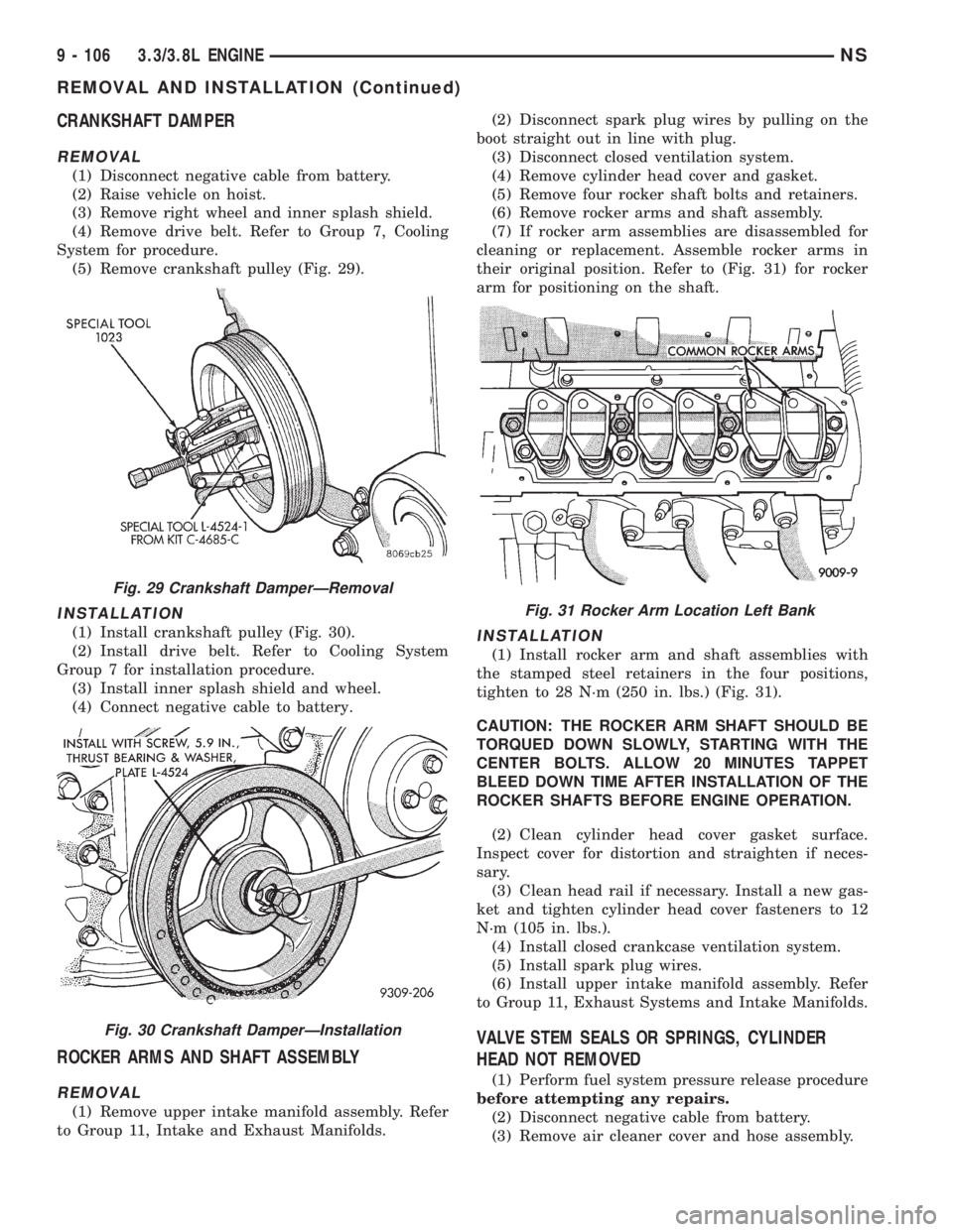
(5) Remove crankshaft pulley (Fig. 29).
INSTALLATION
(1) Install crankshaft pulley (Fig. 30).
(2) Install drive belt. Refer to Cooling System
Group 7 for installation procedure.
(3) Install inner splash shield and wheel.
(4) Connect negative cable to battery.
ROCKER ARMS AND SHAFT ASSEMBLY
REMOVAL
(1) Remove upper intake manifold assembly. Refer
to Group 11, Intake and Exhaust Manifolds.(2) Disconnect spark plug wires by pulling on the
boot straight out in line with plug.
(3) Disconnect closed ventilation system.
(4) Remove cylinder head cover and gasket.
(5) Remove four rocker shaft bolts and retainers.
(6) Remove rocker arms and shaft assembly.
(7) If rocker arm assemblies are disassembled for
cleaning or replacement. Assemble rocker arms in
their original position. Refer to (Fig. 31) for rocker
arm for positioning on the shaft.
INSTALLATION
(1) Install rocker arm and shaft assemblies with
the stamped steel retainers in the four positions,
tighten to 28 N´m (250 in. lbs.) (Fig. 31).
CAUTION: THE ROCKER ARM SHAFT SHOULD BE
TORQUED DOWN SLOWLY, STARTING WITH THE
CENTER BOLTS. ALLOW 20 MINUTES TAPPET
BLEED DOWN TIME AFTER INSTALLATION OF THE
ROCKER SHAFTS BEFORE ENGINE OPERATION.
(2) Clean cylinder head cover gasket surface.
Inspect cover for distortion and straighten if neces-
sary.
(3) Clean head rail if necessary. Install a new gas-
ket and tighten cylinder head cover fasteners to 12
N´m (105 in. lbs.).
(4) Install closed crankcase ventilation system.
(5) Install spark plug wires.
(6) Install upper intake manifold assembly. Refer
to Group 11, Exhaust Systems and Intake Manifolds.
VALVE STEM SEALS OR SPRINGS, CYLINDER
HEAD NOT REMOVED
(1) Perform fuel system pressure release procedure
before attempting any repairs.
(2) Disconnect negative cable from battery.
(3) Remove air cleaner cover and hose assembly.
Fig. 29 Crankshaft DamperÐRemoval
Fig. 30 Crankshaft DamperÐInstallation
Fig. 31 Rocker Arm Location Left Bank
9 - 106 3.3/3.8L ENGINENS
REMOVAL AND INSTALLATION (Continued)
Page 1283 of 1938

FRAME
INDEX
page page
REMOVAL AND INSTALLATION
FRONT CROSSMEMBER MOUNT BUSHINGS . . . 5
FRONT CROSSMEMBER................... 3SPECIFICATIONS
FRAME AND BODY OPENING DIMENSIONS.... 5
REMOVAL AND INSTALLATION
FRONT CROSSMEMBER
The front suspension crossmember must be
installed in the design location to achieve proper
front end suspension alignment. If the crossmember
is removed without applying reference marks on the
frame rails, align the crossmember according to the
dimensions provided in this group.
NOTE: If the caged nuts in the frame rails become
damaged and cannot be reused, a replacement nut
can be obtained through a MoparTParts supplier.
REMOVAL
(1) Disconnect battery negative cable.
(2) Remove steering column lower cover from
instrument panel. Refer to Group 8E, Instrument
Panel and Systems.
(3) Remove knee blocker reinforcement. Refer to
Group 8E, Instrument Panel and Systems.
(4) Position steering so front wheels are straight
ahead.
CAUTION: Do not rotate steering wheel after disen-
gaging lower coupling from steering gear, damage
to airbag clock spring can result.
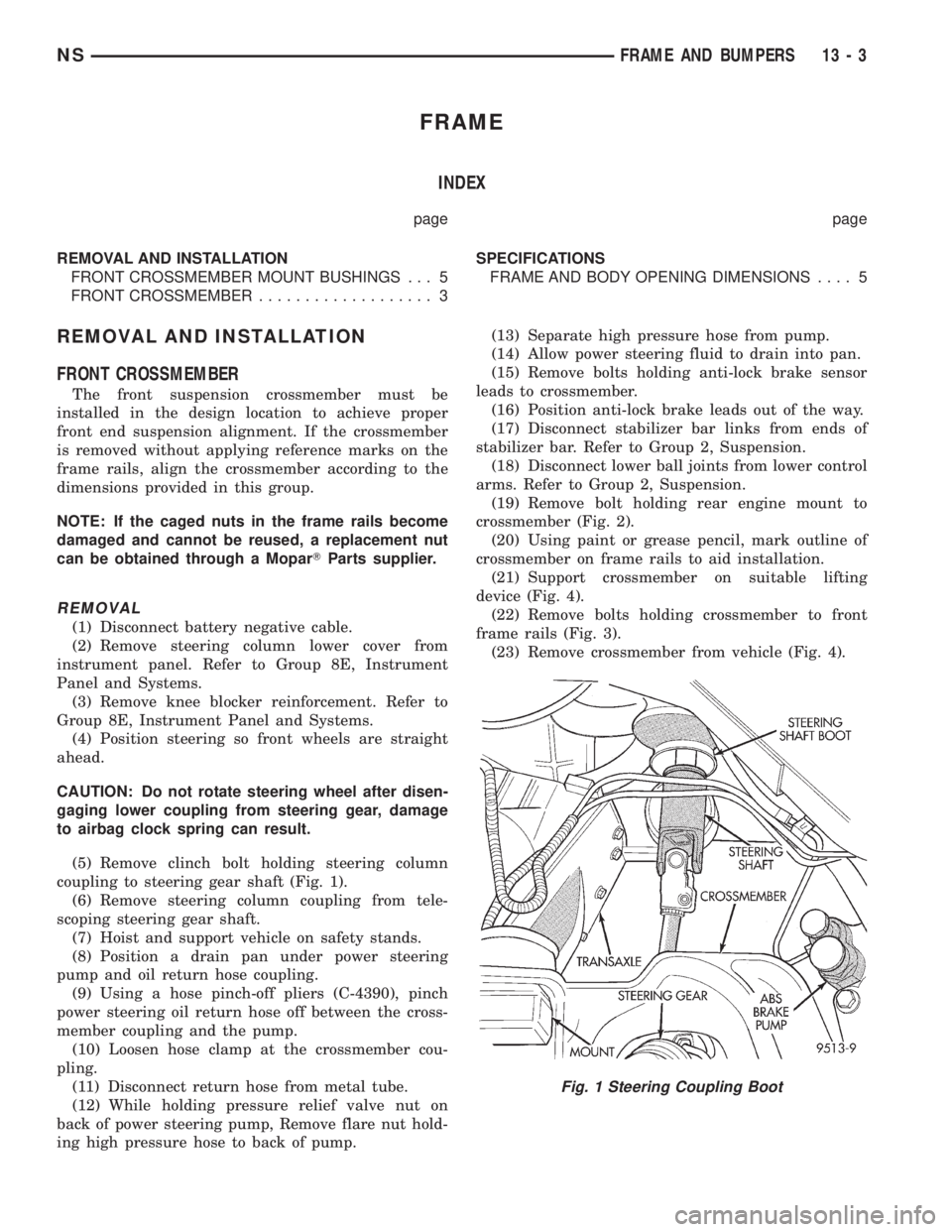
(5) Remove clinch bolt holding steering column
coupling to steering gear shaft (Fig. 1).
(6) Remove steering column coupling from tele-
scoping steering gear shaft.
(7) Hoist and support vehicle on safety stands.
(8) Position a drain pan under power steering
pump and oil return hose coupling.
(9) Using a hose pinch-off pliers (C-4390), pinch
power steering oil return hose off between the cross-
member coupling and the pump.
(10) Loosen hose clamp at the crossmember cou-
pling.
(11) Disconnect return hose from metal tube.
(12) While holding pressure relief valve nut on
back of power steering pump, Remove flare nut hold-
ing high pressure hose to back of pump.(13) Separate high pressure hose from pump.
(14) Allow power steering fluid to drain into pan.
(15) Remove bolts holding anti-lock brake sensor
leads to crossmember.
(16) Position anti-lock brake leads out of the way.
(17) Disconnect stabilizer bar links from ends of
stabilizer bar. Refer to Group 2, Suspension.
(18) Disconnect lower ball joints from lower control
arms. Refer to Group 2, Suspension.
(19) Remove bolt holding rear engine mount to
crossmember (Fig. 2).
(20) Using paint or grease pencil, mark outline of
crossmember on frame rails to aid installation.
(21) Support crossmember on suitable lifting
device (Fig. 4).
(22) Remove bolts holding crossmember to front
frame rails (Fig. 3).
(23) Remove crossmember from vehicle (Fig. 4).
Fig. 1 Steering Coupling Boot
NSFRAME AND BUMPERS 13 - 3
Page 1337 of 1938

(brake, park/neutral, air conditioning). Deceleration
die out is also prevented by increasing airflow when
the throttle is closed quickly after a driving (speed)
condition.
DUTY CYCLE EVAP CANISTER PURGE
SOLENOIDÐPCM OUTPUT
The duty cycle EVAP purge solenoid regulates the
rate of vapor flow from the EVAP canister to the
throttle body. The PCM operates the solenoid.
During the cold start warm-up period and the hot
start time delay, the PCM does not energize the sole-
noid. When de-energized, no vapors are purged. The
PCM de-energizes the solenoid during open loop oper-
ation.
The engine enters closed loop operation after it
reaches a specified temperature and the time delay
ends. During closed loop operation, the PCM ener-
gizes and de-energizes the solenoid 5 or 10 times per
second, depending upon operating conditions. The
PCM varies the vapor flow rate by changing solenoid
pulse width. Pulse width is the amount of time the
solenoid energizes.
A rubber boot covers the duty cycle EVAP purge
solenoid. The solenoid attaches to a bracket mounted
to the right engine mount (Fig. 31). The top of the
solenoid has the word TOP on it. The solenoid will
not operate properly unless it is installed correctly.
PROPORTIONAL PURGE SOLENOID
All vehicles use a proportional purge solenoid. The
solenoid regulates the rate of vapor flow from theEVAP canister to the throttle body. The PCM oper-
ates the solenoid.
During the cold start warm-up period and the hot
start time delay, the PCM does not energize the sole-
noid. When de-energized, no vapors are purged.
The proportional purge solenoid operates at a fre-
quency of 200 hz and is controlled by an engine con-
troller circuit that senses the current being applied
to the proportional purge solenoid and then adjusts
that current to achieve the desired purge flow. The
proportional purge solenoid controls the purge rate of
fuel vapors from the vapor canister and fuel tank to
the engine intake manifold.
ELECTRONIC EGR TRANSDUCER SOLENOIDÐPCM
OUTPUT
The electronic EGR transducer contains an electri-
cally operated solenoid and a back-pressure trans-
ducer (Fig. 33) or (Fig. 34) or (Fig. 35). The PCM
operates the solenoid. The PCM determines when to
energize the solenoid. Exhaust system back-pressure
controls the transducer.
When the PCM energizes the solenoid, vacuum
does not reach the transducer. Vacuum flows to the
transducer when the PCM de-energizes the solenoid.
When exhaust system back-pressure becomes high
enough, it fully closes a bleed valve in the trans-
ducer. When the PCM de-energizes the solenoid and
back-pressure closes the transducer bleed valve, vac-
uum flows through the transducer to operate the
EGR valve.
De-energizing the solenoid, but not fully closing the
transducer bleed hole (because of low back-pressure),
varies the strength of vacuum applied to the EGR
valve. Varying the strength of the vacuum changes
the amount of EGR supplied to the engine. This pro-
Fig. 31 Duty Cycle EVAP Purge Solenoid
Fig. 32 Proportional Purge Solenoid
NSFUEL SYSTEM 14 - 43
DESCRIPTION AND OPERATION (Continued)
Page 1452 of 1938

POWER STEERING GEAR
INDEX
page page
DESCRIPTION AND OPERATION
STEERING GEAR OPERATION DESCRIPTION . 26
DIAGNOSIS AND TESTING
POWER STEERING GEAR................. 27
REMOVAL AND INSTALLATION
STEERING GEAR....................... 27
DISASSEMBLY AND ASSEMBLY
OUTER TIE ROD END................... 33STEERING GEAR INNER TIE ROD BOOT..... 31
SPECIFICATIONS
STEERING GEAR FASTENER TORQUE
SPECIFICATIONS...................... 34
SPECIAL TOOLS
POWER STEERING GEAR................. 35
DESCRIPTION AND OPERATION
STEERING GEAR OPERATION DESCRIPTION
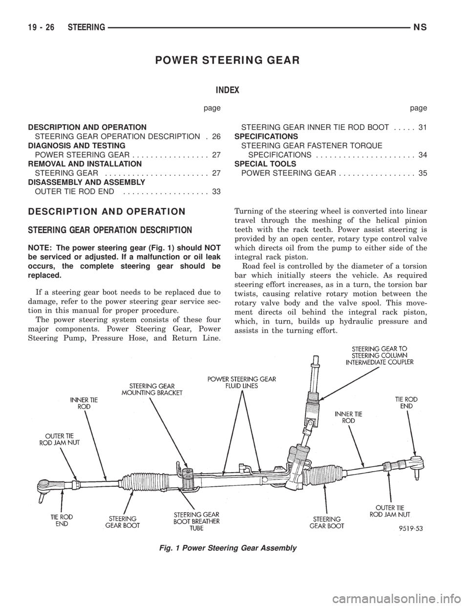
NOTE: The power steering gear (Fig. 1) should NOT
be serviced or adjusted. If a malfunction or oil leak
occurs, the complete steering gear should be
replaced.
If a steering gear boot needs to be replaced due to
damage, refer to the power steering gear service sec-
tion in this manual for proper procedure.
The power steering system consists of these four
major components. Power Steering Gear, Power
Steering Pump, Pressure Hose, and Return Line.Turning of the steering wheel is converted into linear
travel through the meshing of the helical pinion
teeth with the rack teeth. Power assist steering is
provided by an open center, rotary type control valve
which directs oil from the pump to either side of the
integral rack piston.
Road feel is controlled by the diameter of a torsion
bar which initially steers the vehicle. As required
steering effort increases, as in a turn, the torsion bar
twists, causing relative rotary motion between the
rotary valve body and the valve spool. This move-
ment directs oil behind the integral rack piston,
which, in turn, builds up hydraulic pressure and
assists in the turning effort.
Fig. 1 Power Steering Gear Assembly
19 - 26 STEERINGNS
Page 1457 of 1938

CAUTION: Proper torque on the cradle plate to
suspension cradle mounting bolts is very impor-
tant.
(8) Install cradle plate on front suspension cradle
and install the 10 cradle plate to cradle attaching
bolts and nuts (Fig. 8). Tighten all attaching bolts to
a torque of 165 N´m (123 ft. lbs.).
(9) Install the bracket (Fig. 9) attaching the power
steering fluid tubes to the front suspension cradle.
CAUTION:
(10) Install the power steering fluid return hose on
the steel tube at the front suspension cradle (Fig. 4).
(11) Install a screw type hose clamp on the power
steering hose to steel tube connection.Be sure hose
clamp is installed on return tube past the upset
bead on the tube.Tighten the screw clamp to a
torque of 2 N´m (18 in. lbs.).
CAUTION: The protective heat shield sleeves must
cover the entire rubber hose and hose to tube con-
nection portion of both the power steering fluid
pressure and return hoses (Fig. 4). This is required
to prevent the power steering hoses from being
overheated.
(12) When used, properly position the protective
heat sleeves on the power steering hoses. Then, tie
strap the heat sleeves to the power steering hoses to
keep them in their proper position.
(13) Install the front tire and wheel assemblies on
vehicle. Install the wheel lug nuts and torque to 129
N´m (95 ft. lbs.).
(14) Lower the vehicle to a level were the interior
of vehicle is accessible.
(15) Using the intermediate coupler, turn the front
wheels of the vehicle to the left until the intermedi-
ate coupler shaft is properly aligned with the steer-
ing column coupler. Assemble the steering column
shaft coupler (Fig. 3) onto the steering gear interme-
diate coupler. Install steering column coupler to
intermediate shaft retaining pinch bolt (Fig. 3).
Tighten the pinch bolt nut to a torque of 28 N´m (250
in. lbs.).
CAUTION: Do not use automatic transmission fluid
in the power steering system. Only use Mopar,
Power Steering Fluid or an exact equivalent prod-
uct.
(16) Fill power steering pump fluid reservoir to the
proper level.
(17) Start the engine and let run for a few seconds.
Then turn the engine off.(18) Add fluid if necessary. Repeat the above pro-
cedure until the fluid level remains constant after
running the engine.
(19) Raise front wheels of vehicle off the ground.
(20) Start the engine. Slowly turn the steering
wheel right and left, lightly contacting the wheel
stops. Then turn the engine off.
(21) Add power steering fluid if necessary.
(22) Lower the vehicle and turn the steering wheel
slowly from lock to lock.
(23) Stop the engine. Check the fluid level and
refill as required.
(24) If the fluid is extremely foamy, allow the vehi-
cle to stand a few minutes and repeat the above pro-
cedure.
(25) Fill power steering reservoir to correct level
with Mopart, Power Steering Fluid, or equivalent.
(26) Adjust toe (Refer to Group 2 Suspension).
DISASSEMBLY AND ASSEMBLY
STEERING GEAR INNER TIE ROD BOOT
DISASSEMBLE
NOTE: The removal and installation of the inner tie
rod boot must be performed with the steering gear
assembly removed from the vehicle.
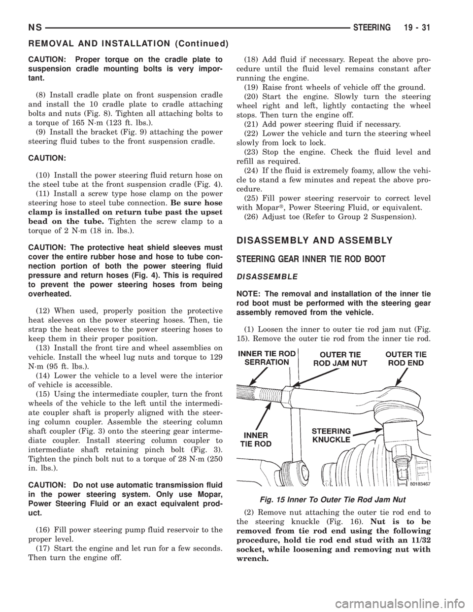
(1) Loosen the inner to outer tie rod jam nut (Fig.
15). Remove the outer tie rod from the inner tie rod.
(2) Remove nut attaching the outer tie rod end to
the steering knuckle (Fig. 16).Nut is to be
removed from tie rod end using the following
procedure, hold tie rod end stud with an 11/32
socket, while loosening and removing nut with
wrench.
Fig. 15 Inner To Outer Tie Rod Jam Nut
NSSTEERING 19 - 31
REMOVAL AND INSTALLATION (Continued)