Page 1815 of 1938

BODY COMPONENT SERVICE
INDEX
page page
REMOVAL AND INSTALLATION
GEARSHIFT CONSOLE.................... 3LIFTGATE CHMSL ACCESS PANEL........... 3
REMOVAL AND INSTALLATION
GEARSHIFT CONSOLE
REMOVAL
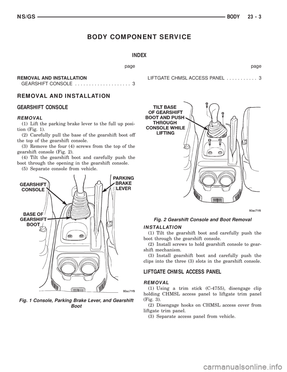
(1) Lift the parking brake lever to the full up posi-
tion (Fig. 1).
(2) Carefully pull the base of the gearshift boot off
the top of the gearshift console.
(3) Remove the four (4) screws from the top of the
gearshift console (Fig. 2).
(4) Tilt the gearshift boot and carefully push the
boot through the opening in the gearshift console.
(5) Separate console from vehicle.
INSTALLATION
(1) Tilt the gearshift boot and carefully push the
boot through the gearshift console.
(2) Install screws to hold gearshift console to gear-
shift mechanism.
(3) Install gearshift boot and carefully push the
clips into the three (3) slots in the gearshift console.
LIFTGATE CHMSL ACCESS PANEL
REMOVAL
(1) Using a trim stick (C-4755), disengage clip
holding CHMSL access panel to liftgate trim panel
(Fig. 3).
(2) Disengage hooks on CHMSL access cover from
liftgate trim panel.
(3) Separate access panel from vehicle.
Fig. 1 Console, Parking Brake Lever, and Gearshift
Boot
Fig. 2 Gearshift Console and Boot Removal
NS/GSBODY 23 - 3
Page 1846 of 1938

(10) Disconnect the two upper mounts from the
upper reinforcement and the lower mount from the
tunnel.
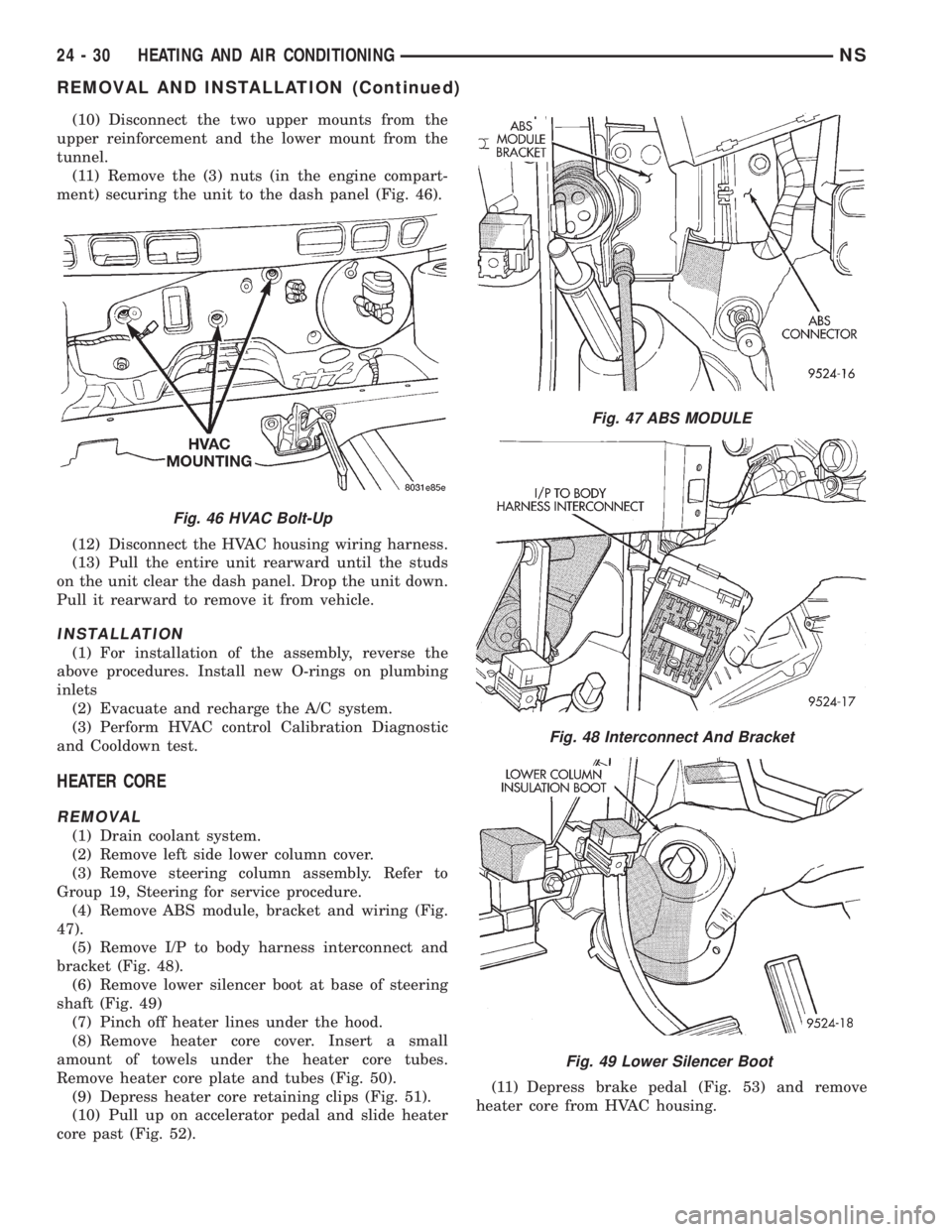
(11) Remove the (3) nuts (in the engine compart-
ment) securing the unit to the dash panel (Fig. 46).
(12) Disconnect the HVAC housing wiring harness.
(13) Pull the entire unit rearward until the studs
on the unit clear the dash panel. Drop the unit down.
Pull it rearward to remove it from vehicle.
INSTALLATION
(1) For installation of the assembly, reverse the
above procedures. Install new O-rings on plumbing
inlets
(2) Evacuate and recharge the A/C system.
(3) Perform HVAC control Calibration Diagnostic
and Cooldown test.
HEATER CORE
REMOVAL
(1) Drain coolant system.
(2) Remove left side lower column cover.
(3) Remove steering column assembly. Refer to
Group 19, Steering for service procedure.
(4) Remove ABS module, bracket and wiring (Fig.
47).
(5) Remove I/P to body harness interconnect and
bracket (Fig. 48).
(6) Remove lower silencer boot at base of steering
shaft (Fig. 49)
(7) Pinch off heater lines under the hood.
(8) Remove heater core cover. Insert a small
amount of towels under the heater core tubes.
Remove heater core plate and tubes (Fig. 50).
(9) Depress heater core retaining clips (Fig. 51).
(10) Pull up on accelerator pedal and slide heater
core past (Fig. 52).(11) Depress brake pedal (Fig. 53) and remove
heater core from HVAC housing.
Fig. 46 HVAC Bolt-Up
Fig. 47 ABS MODULE
Fig. 48 Interconnect And Bracket
Fig. 49 Lower Silencer Boot
24 - 30 HEATING AND AIR CONDITIONINGNS
REMOVAL AND INSTALLATION (Continued)
Page 1892 of 1938

(2) Hand-start the stud into the expansion valve
and torque to7-11N´m(64-96in.lbs.).
(3) Carefully install the expansion valve to the
sealing plate. Install the two screws and tighten 8 to
14 N´m (70 to 130 in. lbs.) torque.
(4) Carefully install the refrigerant lines and seal-
ing plate to the expansion valve. Install the nut and
tighten 20 to 26 N´m (170 to 230 in. lbs.) torque.
(5) Install the ground wire at dash panel.
(6) Pull generator back into the proper position for
bracket mounting.
(7) Install generator field wire connector.
(8) Install the upper generator bracket.
(9) Install accessory drive belt.
(10) Evacuate and recharge system.
(11) After expansion valve is installed, the system
is charged, and leaks have checked repeat the A/C
performance check.
FILTER-DRIER ASSEMBLY
REMOVAL
WARNING: THE REFRIGERATION SYSTEM MUST
BE COMPLETELY EMPTY BEFORE PROCEEDING
WITH THIS OPERATION.
(1) Recover A/C system refrigerant.
(2) Remove liquid line at filter-drier (Fig. 21).
(3) Remove the (2) bolts holding filter-drier bracket
to radiator fan module bracket.
(4) Remove the lower liquid line at condenser.
(5) Remove the upper radiator crossmember.
(6) Pull up on radiator and slide filter-drier from
the mounting location.
INSTALLATION
(1) Before installation, replace both refrigerant
line O-rings. Then reverse the above procedures.
(2) Evacuate and recharge system.
HEATER A/C UNIT HOUSING
REMOVAL
WARNING: IF EQUIPPED WITH AIR CONDITIONING,
THE REFRIGERATION SYSTEM MUST BE COM-
PLETELY EMPTY BEFORE PROCEEDING.
(1) Set parking brake.
(2) Disconnect battery negative cable.
(3) Using a refrigerant recovery machine, remove
refrigerant from the A/C system.
(4) Remove wiper module. Refer to Group 8K,
Windshield Wipers and Washers.
(5) Drain engine coolant. Remove heater hoses at
the heater core, refer to Heater Hoses Removal and
Installation procedures. Plug coolant lines.(6) Remove suction and liquid lines at the expan-
sion valve (Fig. 27).
(7) Remove the Instrument Panel Assembly. Refer
to Group 8E, Instrument Panel and Systems.
(8) Remove heater ducts.
(9) Disconnect the two upper mounts from the
upper reinforcement and the lower mount from the
tunnel.
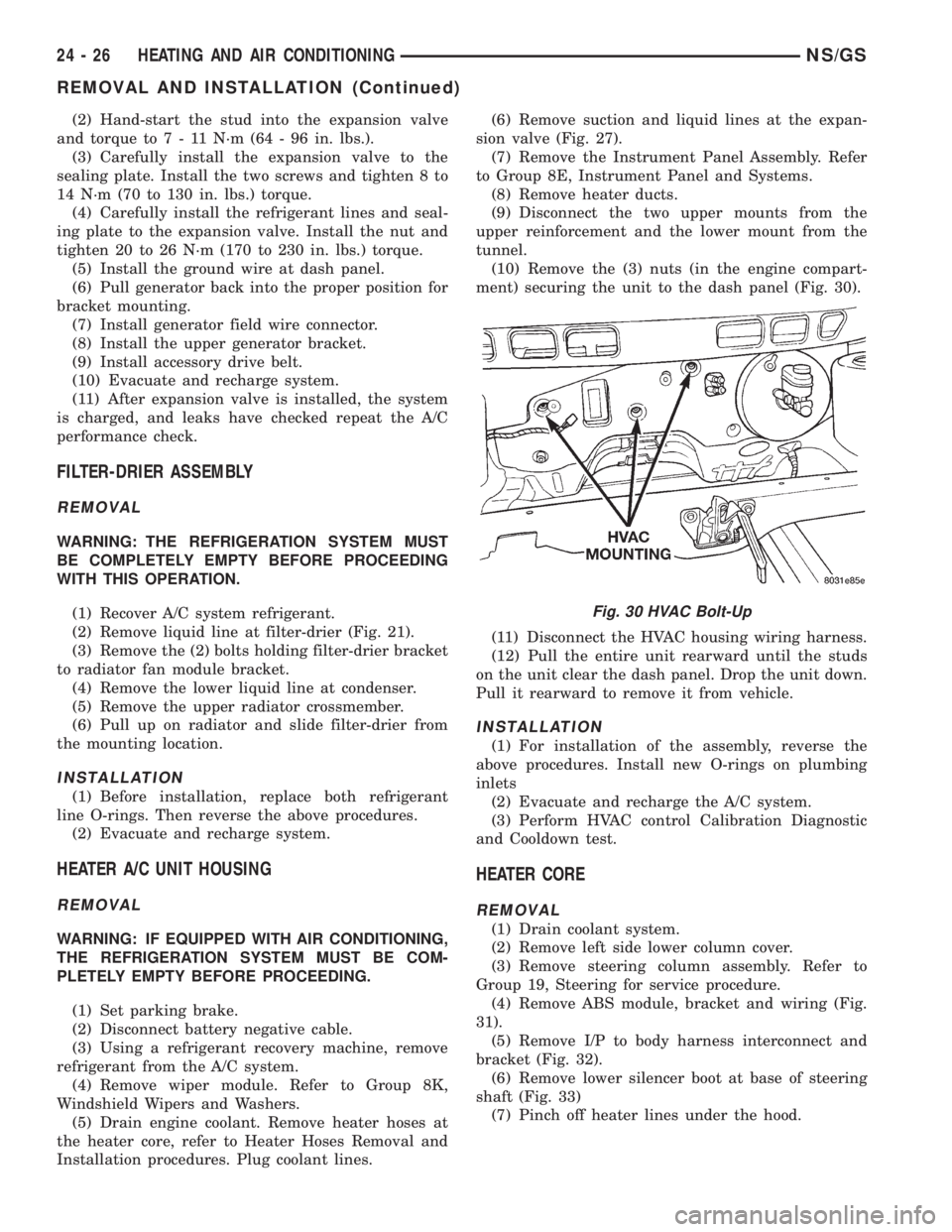
(10) Remove the (3) nuts (in the engine compart-
ment) securing the unit to the dash panel (Fig. 30).
(11) Disconnect the HVAC housing wiring harness.
(12) Pull the entire unit rearward until the studs
on the unit clear the dash panel. Drop the unit down.
Pull it rearward to remove it from vehicle.
INSTALLATION
(1) For installation of the assembly, reverse the
above procedures. Install new O-rings on plumbing
inlets
(2) Evacuate and recharge the A/C system.
(3) Perform HVAC control Calibration Diagnostic
and Cooldown test.
HEATER CORE
REMOVAL
(1) Drain coolant system.
(2) Remove left side lower column cover.
(3) Remove steering column assembly. Refer to
Group 19, Steering for service procedure.
(4) Remove ABS module, bracket and wiring (Fig.
31).
(5) Remove I/P to body harness interconnect and
bracket (Fig. 32).
(6) Remove lower silencer boot at base of steering
shaft (Fig. 33)
(7) Pinch off heater lines under the hood.
Fig. 30 HVAC Bolt-Up
24 - 26 HEATING AND AIR CONDITIONINGNS/GS
REMOVAL AND INSTALLATION (Continued)
Page 1893 of 1938
(8) Remove heater core cover. Insert a small
amount of towels under the heater core tubes.
Remove heater core plate and tubes (Fig. 34).
(9) Depress heater core retaining clips (Fig. 35).(10) Pull up on accelerator pedal and slide heater
core past (Fig. 36).
(11) Depress brake pedal (Fig. 37) and remove
heater core from HVAC housing.
Fig. 31 ABS MODULE
Fig. 32 Interconnect And Bracket
Fig. 33 Lower Silencer Boot
Fig. 34 Heater Core Plate And Tubes
Fig. 35 Depress Clips
Fig. 36 Accelerator Pedal
NS/GSHEATING AND AIR CONDITIONING 24 - 27
REMOVAL AND INSTALLATION (Continued)