1996 CHRYSLER VOYAGER boot
[x] Cancel search: bootPage 1458 of 1938
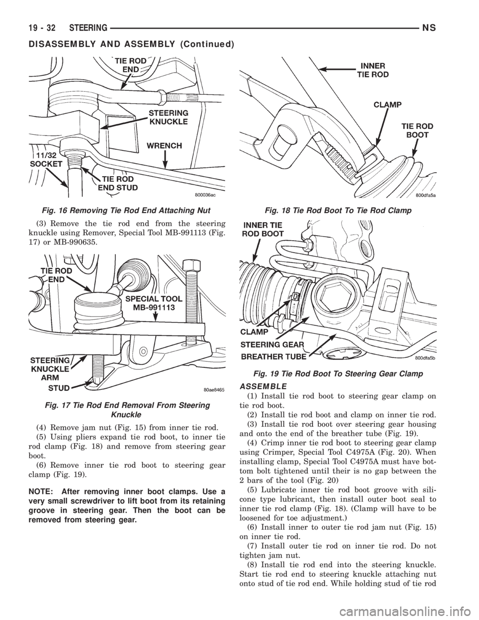
(3) Remove the tie rod end from the steering
knuckle using Remover, Special Tool MB-991113 (Fig.
17) or MB-990635.
(4) Remove jam nut (Fig. 15) from inner tie rod.
(5) Using pliers expand tie rod boot, to inner tie
rod clamp (Fig. 18) and remove from steering gear
boot.
(6) Remove inner tie rod boot to steering gear
clamp (Fig. 19).
NOTE: After removing inner boot clamps. Use a
very small screwdriver to lift boot from its retaining
groove in steering gear. Then the boot can be
removed from steering gear.
ASSEMBLE
(1) Install tie rod boot to steering gear clamp on
tie rod boot.
(2) Install tie rod boot and clamp on inner tie rod.
(3) Install tie rod boot over steering gear housing
and onto the end of the breather tube (Fig. 19).
(4) Crimp inner tie rod boot to steering gear clamp
using Crimper, Special Tool C4975A (Fig. 20). When
installing clamp, Special Tool C4975A must have bot-
tom bolt tightened until their is no gap between the
2 bars of the tool (Fig. 20)
(5) Lubricate inner tie rod boot groove with sili-
cone type lubricant, then install outer boot seal to
inner tie rod clamp (Fig. 18). (Clamp will have to be
loosened for toe adjustment.)
(6) Install inner to outer tie rod jam nut (Fig. 15)
on inner tie rod.
(7) Install outer tie rod on inner tie rod. Do not
tighten jam nut.
(8) Install tie rod end into the steering knuckle.
Start tie rod end to steering knuckle attaching nut
onto stud of tie rod end. While holding stud of tie rod
Fig. 16 Removing Tie Rod End Attaching Nut
Fig. 17 Tie Rod End Removal From Steering
Knuckle
Fig. 18 Tie Rod Boot To Tie Rod Clamp
Fig. 19 Tie Rod Boot To Steering Gear Clamp
19 - 32 STEERINGNS
DISASSEMBLY AND ASSEMBLY (Continued)
Page 1459 of 1938
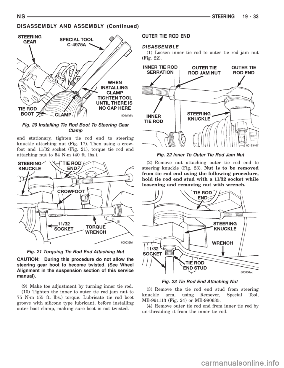
end stationary, tighten tie rod end to steering
knuckle attaching nut (Fig. 17). Then using a crow-
foot and 11/32 socket (Fig. 21), torque tie rod end
attaching nut to 54 N´m (40 ft. lbs.).
CAUTION: During this procedure do not allow the
steering gear boot to become twisted. (See Wheel
Alignment in the suspension section of this service
manual).
(9) Make toe adjustment by turning inner tie rod.
(10) Tighten the inner to outer tie rod jam nut to
75 N´m (55 ft. lbs.) torque. Lubricate tie rod boot
groove with silicone type lubricant, before installing
outer boot clamp, making sure boot is not twisted.
OUTER TIE ROD END
DISASSEMBLE
(1) Loosen inner tie rod to outer tie rod jam nut
(Fig. 22).
(2) Remove nut attaching outer tie rod end to
steering knuckle (Fig. 23).Nut is to be removed
from tie rod end using the following procedure,
hold tie rod end stud with a 11/32 socket while
loosening and removing nut with wrench.
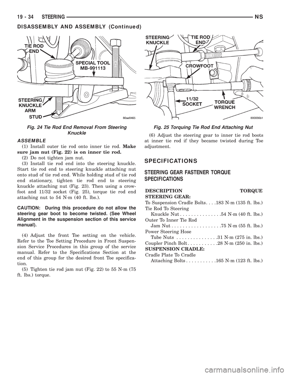
(3) Remove the tie rod end stud from steering
knuckle arm, using Remover, Special Tool,
MB-991113 (Fig. 24) or MB-990635.
(4) Remove outer tie rod end from inner tie rod by
un-threading it from the inner tie rod.
Fig. 20 Installing Tie Rod Boot To Steering Gear
Clamp
Fig. 21 Torquing Tie Rod End Attaching Nut
Fig. 22 Inner To Outer Tie Rod Jam Nut
Fig. 23 Tie Rod End Attaching Nut
NSSTEERING 19 - 33
DISASSEMBLY AND ASSEMBLY (Continued)
Page 1460 of 1938
ASSEMBLE
(1) Install outer tie rod onto inner tie rod.Make
sure jam nut (Fig. 22) is on inner tie rod.
(2) Do not tighten jam nut.
(3) Install tie rod end into the steering knuckle.
Start tie rod end to steering knuckle attaching nut
onto stud of tie rod end. While holding stud of tie rod
end stationary, tighten tie rod end to steering
knuckle attaching nut (Fig. 23). Then using a crow-
foot and 11/32 socket (Fig. 25), torque tie rod end
attaching nut to 54 N´m (40 ft. lbs.).
CAUTION: During this procedure do not allow the
steering gear boot to become twisted. (See Wheel
Alignment in the suspension section of this service
manual).
(4) Adjust the front Toe setting on the vehicle.
Refer to the Toe Setting Procedure in Front Suspen-
sion Service Procedures in this group of the service
manual. Refer to the Specifications Section at the
end of this group for the desired front Toe specifica-
tion.
(5) Tighten tie rod jam nut (Fig. 22) to 55 N´m (75
ft. lbs.) torque.(6) Adjust the steering gear to inner tie rod boots
at inner tie rod if they became twisted during Toe
adjustment.
SPECIFICATIONS
STEERING GEAR FASTENER TORQUE
SPECIFICATIONS
DESCRIPTION TORQUE
STEERING GEAR:
To Suspension Cradle Bolts. . . .183 N´m (135 ft. lbs.)
Tie Rod To Steering
Knuckle Nut...............54N´m(40ft.lbs.)
Outer To Inner Tie Rod
JamNut..................75N´m(55ft.lbs.)
Power Steering Hose
Tube Nuts...............31N´m(275 in. lbs.)
Coupler Pinch Bolt...........28N´m(250 in. lbs.)
SUSPENSION CRADLE:
Cradle Plate To Cradle
Attaching Bolts...........165 N´m (123 ft. lbs.)
Fig. 24 Tie Rod End Removal From Steering
KnuckleFig. 25 Torquing Tie Rod End Attaching Nut
19 - 34 STEERINGNS
DISASSEMBLY AND ASSEMBLY (Continued)
Page 1461 of 1938
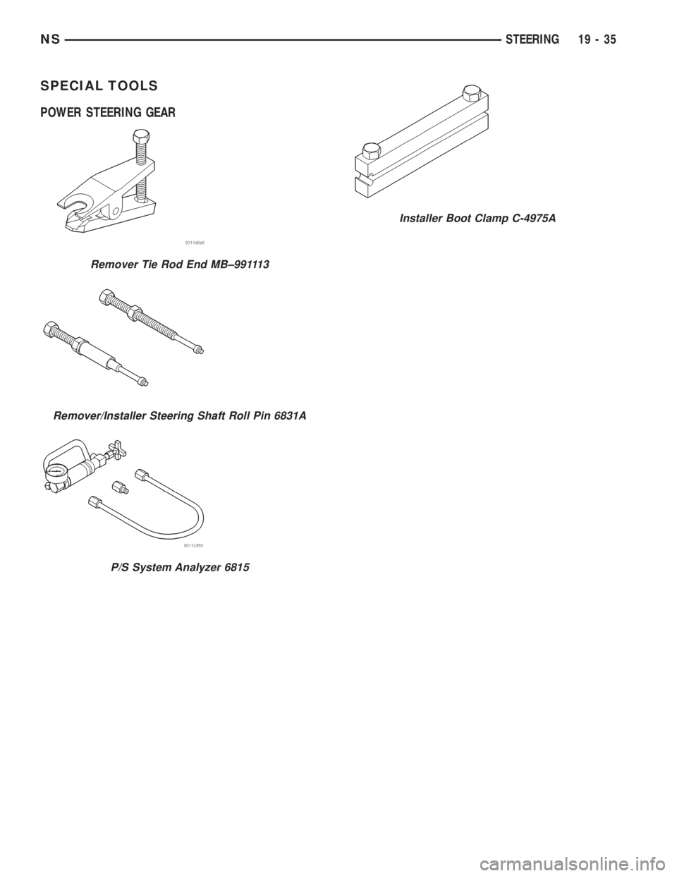
SPECIAL TOOLS
POWER STEERING GEAR
Remover Tie Rod End MB±991113
Remover/Installer Steering Shaft Roll Pin 6831A
P/S System Analyzer 6815
Installer Boot Clamp C-4975A
NSSTEERING 19 - 35
Page 1657 of 1938
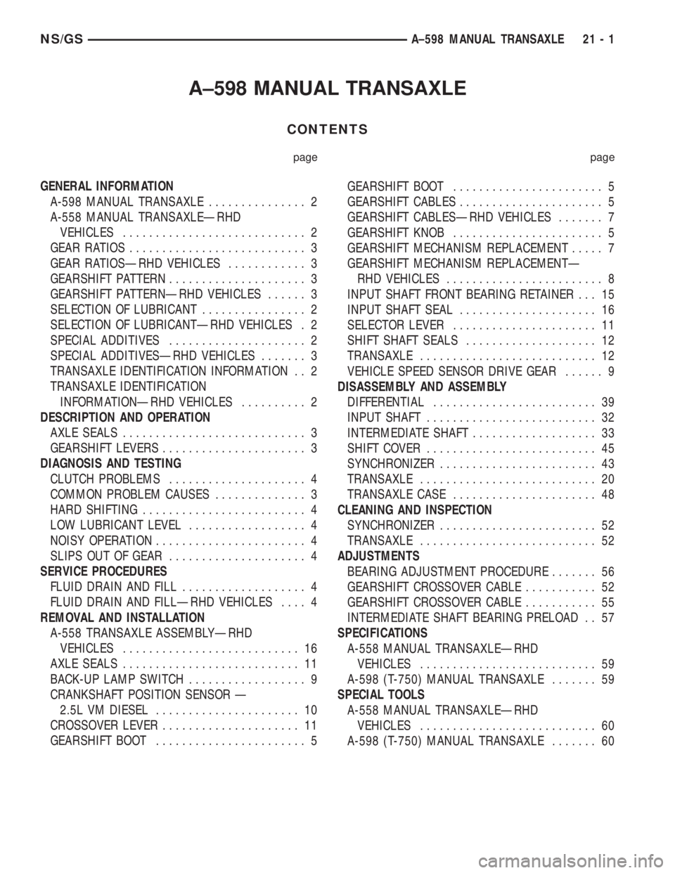
A±598 MANUAL TRANSAXLE
CONTENTS
page page
GENERAL INFORMATION
A-598 MANUAL TRANSAXLE............... 2
A-558 MANUAL TRANSAXLEÐRHD
VEHICLES............................ 2
GEAR RATIOS........................... 3
GEAR RATIOSÐRHD VEHICLES............ 3
GEARSHIFT PATTERN..................... 3
GEARSHIFT PATTERNÐRHD VEHICLES...... 3
SELECTION OF LUBRICANT................ 2
SELECTION OF LUBRICANTÐRHD VEHICLES . 2
SPECIAL ADDITIVES..................... 2
SPECIAL ADDITIVESÐRHD VEHICLES....... 3
TRANSAXLE IDENTIFICATION INFORMATION . . 2
TRANSAXLE IDENTIFICATION
INFORMATIONÐRHD VEHICLES.......... 2
DESCRIPTION AND OPERATION
AXLE SEALS............................ 3
GEARSHIFT LEVERS...................... 3
DIAGNOSIS AND TESTING
CLUTCH PROBLEMS..................... 4
COMMON PROBLEM CAUSES.............. 3
HARD SHIFTING......................... 4
LOW LUBRICANT LEVEL.................. 4
NOISY OPERATION....................... 4
SLIPS OUT OF GEAR..................... 4
SERVICE PROCEDURES
FLUID DRAIN AND FILL................... 4
FLUID DRAIN AND FILLÐRHD VEHICLES.... 4
REMOVAL AND INSTALLATION
A-558 TRANSAXLE ASSEMBLYÐRHD
VEHICLES........................... 16
AXLE SEALS........................... 11
BACK-UP LAMP SWITCH.................. 9
CRANKSHAFT POSITION SENSOR Ð
2.5L VM DIESEL...................... 10
CROSSOVER LEVER..................... 11
GEARSHIFT BOOT....................... 5GEARSHIFT BOOT....................... 5
GEARSHIFT CABLES...................... 5
GEARSHIFT CABLESÐRHD VEHICLES....... 7
GEARSHIFT KNOB....................... 5
GEARSHIFT MECHANISM REPLACEMENT..... 7
GEARSHIFT MECHANISM REPLACEMENTÐ
RHD VEHICLES........................ 8
INPUT SHAFT FRONT BEARING RETAINER . . . 15
INPUT SHAFT SEAL..................... 16
SELECTOR LEVER...................... 11
SHIFT SHAFT SEALS.................... 12
TRANSAXLE........................... 12
VEHICLE SPEED SENSOR DRIVE GEAR...... 9
DISASSEMBLY AND ASSEMBLY
DIFFERENTIAL......................... 39
INPUT SHAFT.......................... 32
INTERMEDIATE SHAFT................... 33
SHIFT COVER.......................... 45
SYNCHRONIZER........................ 43
TRANSAXLE........................... 20
TRANSAXLE CASE...................... 48
CLEANING AND INSPECTION
SYNCHRONIZER........................ 52
TRANSAXLE........................... 52
ADJUSTMENTS
BEARING ADJUSTMENT PROCEDURE....... 56
GEARSHIFT CROSSOVER CABLE........... 52
GEARSHIFT CROSSOVER CABLE........... 55
INTERMEDIATE SHAFT BEARING PRELOAD . . 57
SPECIFICATIONS
A-558 MANUAL TRANSAXLEÐRHD
VEHICLES........................... 59
A-598 (T-750) MANUAL TRANSAXLE....... 59
SPECIAL TOOLS
A-558 MANUAL TRANSAXLEÐRHD
VEHICLES........................... 60
A-598 (T-750) MANUAL TRANSAXLE....... 60
NS/GSA±598 MANUAL TRANSAXLE 21 - 1
Page 1661 of 1938
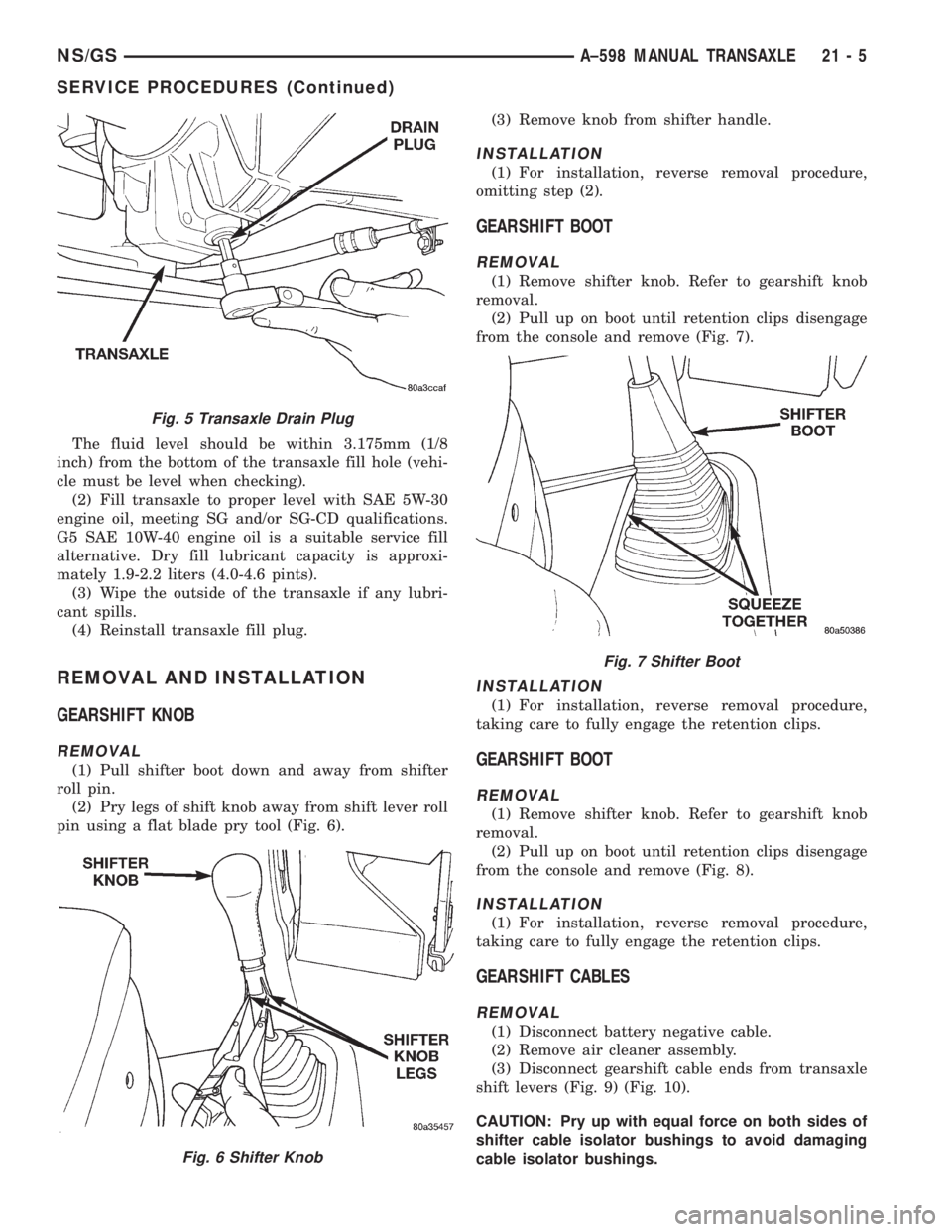
The fluid level should be within 3.175mm (1/8
inch) from the bottom of the transaxle fill hole (vehi-
cle must be level when checking).
(2) Fill transaxle to proper level with SAE 5W-30
engine oil, meeting SG and/or SG-CD qualifications.
G5 SAE 10W-40 engine oil is a suitable service fill
alternative. Dry fill lubricant capacity is approxi-
mately 1.9-2.2 liters (4.0-4.6 pints).
(3) Wipe the outside of the transaxle if any lubri-
cant spills.
(4) Reinstall transaxle fill plug.
REMOVAL AND INSTALLATION
GEARSHIFT KNOB
REMOVAL
(1) Pull shifter boot down and away from shifter
roll pin.
(2) Pry legs of shift knob away from shift lever roll
pin using a flat blade pry tool (Fig. 6).(3) Remove knob from shifter handle.
INSTALLATION
(1) For installation, reverse removal procedure,
omitting step (2).
GEARSHIFT BOOT
REMOVAL
(1) Remove shifter knob. Refer to gearshift knob
removal.
(2) Pull up on boot until retention clips disengage
from the console and remove (Fig. 7).
INSTALLATION
(1) For installation, reverse removal procedure,
taking care to fully engage the retention clips.
GEARSHIFT BOOT
REMOVAL
(1) Remove shifter knob. Refer to gearshift knob
removal.
(2) Pull up on boot until retention clips disengage
from the console and remove (Fig. 8).
INSTALLATION
(1) For installation, reverse removal procedure,
taking care to fully engage the retention clips.
GEARSHIFT CABLES
REMOVAL
(1) Disconnect battery negative cable.
(2) Remove air cleaner assembly.
(3) Disconnect gearshift cable ends from transaxle
shift levers (Fig. 9) (Fig. 10).
CAUTION: Pry up with equal force on both sides of
shifter cable isolator bushings to avoid damaging
cable isolator bushings.
Fig. 5 Transaxle Drain Plug
Fig. 6 Shifter Knob
Fig. 7 Shifter Boot
NS/GSA±598 MANUAL TRANSAXLE 21 - 5
SERVICE PROCEDURES (Continued)
Page 1662 of 1938
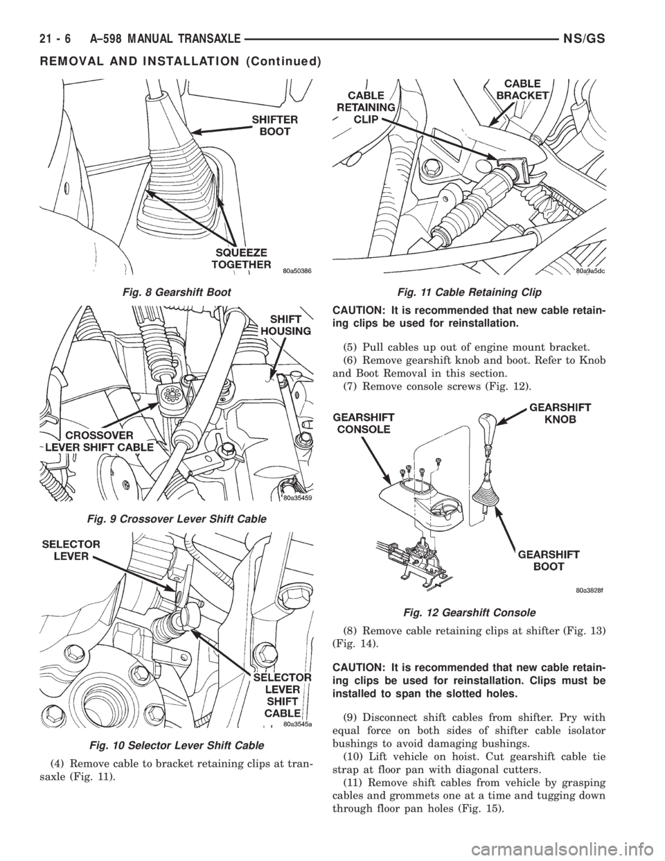
(4) Remove cable to bracket retaining clips at tran-
saxle (Fig. 11).CAUTION: It is recommended that new cable retain-
ing clips be used for reinstallation.
(5) Pull cables up out of engine mount bracket.
(6) Remove gearshift knob and boot. Refer to Knob
and Boot Removal in this section.
(7) Remove console screws (Fig. 12).
(8) Remove cable retaining clips at shifter (Fig. 13)
(Fig. 14).
CAUTION: It is recommended that new cable retain-
ing clips be used for reinstallation. Clips must be
installed to span the slotted holes.
(9) Disconnect shift cables from shifter. Pry with
equal force on both sides of shifter cable isolator
bushings to avoid damaging bushings.
(10) Lift vehicle on hoist. Cut gearshift cable tie
strap at floor pan with diagonal cutters.
(11) Remove shift cables from vehicle by grasping
cables and grommets one at a time and tugging down
through floor pan holes (Fig. 15).
Fig. 8 Gearshift Boot
Fig. 9 Crossover Lever Shift Cable
Fig. 10 Selector Lever Shift Cable
Fig. 11 Cable Retaining Clip
Fig. 12 Gearshift Console
21 - 6 A±598 MANUAL TRANSAXLENS/GS
REMOVAL AND INSTALLATION (Continued)
Page 1663 of 1938
INSTALLATION
(1) To install, reverse removal procedure. After
cables have been replaced, cable adjustment should
be checked. Refer to cable adjustment procedure in
this section.
NOTE: High temperature tie straps must be used
when replacing cable(s). Locate the new tie strap at
the white band on the crossover cable and cinch
cables tightly together.
CAUTION: Only the crossover cable is adjustable.
The selector cable does not have any adjustment
capabilities.
GEARSHIFT CABLESÐRHD VEHICLES
REMOVAL
(1) Disconnect battery negative cable.
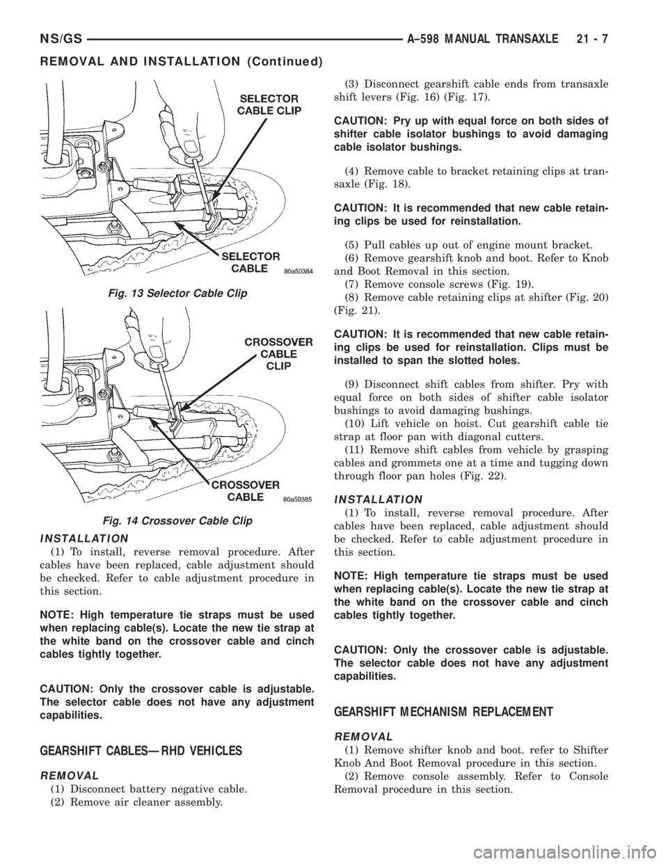
(2) Remove air cleaner assembly.(3) Disconnect gearshift cable ends from transaxle
shift levers (Fig. 16) (Fig. 17).
CAUTION: Pry up with equal force on both sides of
shifter cable isolator bushings to avoid damaging
cable isolator bushings.
(4) Remove cable to bracket retaining clips at tran-
saxle (Fig. 18).
CAUTION: It is recommended that new cable retain-
ing clips be used for reinstallation.
(5) Pull cables up out of engine mount bracket.
(6) Remove gearshift knob and boot. Refer to Knob
and Boot Removal in this section.
(7) Remove console screws (Fig. 19).
(8) Remove cable retaining clips at shifter (Fig. 20)
(Fig. 21).
CAUTION: It is recommended that new cable retain-
ing clips be used for reinstallation. Clips must be
installed to span the slotted holes.
(9) Disconnect shift cables from shifter. Pry with
equal force on both sides of shifter cable isolator
bushings to avoid damaging bushings.
(10) Lift vehicle on hoist. Cut gearshift cable tie
strap at floor pan with diagonal cutters.
(11) Remove shift cables from vehicle by grasping
cables and grommets one at a time and tugging down
through floor pan holes (Fig. 22).
INSTALLATION
(1) To install, reverse removal procedure. After
cables have been replaced, cable adjustment should
be checked. Refer to cable adjustment procedure in
this section.
NOTE: High temperature tie straps must be used
when replacing cable(s). Locate the new tie strap at
the white band on the crossover cable and cinch
cables tightly together.
CAUTION: Only the crossover cable is adjustable.
The selector cable does not have any adjustment
capabilities.
GEARSHIFT MECHANISM REPLACEMENT
REMOVAL
(1) Remove shifter knob and boot. refer to Shifter
Knob And Boot Removal procedure in this section.
(2) Remove console assembly. Refer to Console
Removal procedure in this section.
Fig. 13 Selector Cable Clip
Fig. 14 Crossover Cable Clip
NS/GSA±598 MANUAL TRANSAXLE 21 - 7
REMOVAL AND INSTALLATION (Continued)