1996 CHRYSLER VOYAGER key battery
[x] Cancel search: key batteryPage 1318 of 1938
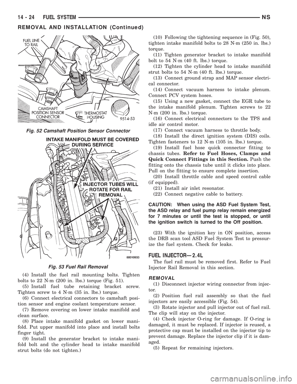
(4) Install the fuel rail mounting bolts. Tighten
bolts to 22 N´m (200 in. lbs.) torque (Fig. 51).
(5) Install fuel tube retaining bracket screw.
Tighten screw to 4 N´m (35 in. lbs.) torque.
(6) Connect electrical connectors to camshaft posi-
tion sensor and engine coolant temperature sensor.
(7) Remove covering on lower intake manifold and
clean surface.
(8) Place intake manifold gasket on lower mani-
fold. Put upper manifold into place and install bolts
finger tight.
(9) Install the generator bracket to intake mani-
fold bolt and the cylinder head to intake manifold
strut bolts (do not tighten.)(10) Following the tightening sequence in (Fig. 50),
tighten intake manifold bolts to 28 N´m (250 in. lbs.)
torque.
(11) Tighten generator bracket to intake manifold
bolt to 54 N´m (40 ft. lbs.) torque.
(12) Tighten the cylinder head to intake manifold
strut bolts to 54 N´m (40 ft. lbs.) torque.
(13) Connect ground strap and MAP sensor electri-
cal connector.
(14) Connect vacuum harness to intake plenum.
Connect PCV system hoses.
(15) Using a new gasket, connect the EGR tube to
the intake manifold plenum. Tighten screws to 22
N´m (200 in. lbs.) torque.
(16) Connect electrical connectors to the TPS and
idle air control motor.
(17) Connect vacuum harness to throttle body.
(18) Install the direct ignition system (DIS) coils.
Tighten fasteners to 12 N´m (105 in. lbs.) torque.
(19) Install fuel hose quick connector fitting to
chassis tubes.Refer to Fuel Hoses, Clamps and
Quick Connect Fittings in this Section.Push the
fitting onto the chassis tube until it clicks into place.
Pull on the fitting to ensure complete insertion.
(20) Install throttle cable and speed control cable
(if equipped).
(21) Install air inlet resonator.
(22) Connect negative cable to battery.
CAUTION: When using the ASD Fuel System Test,
the ASD relay and fuel pump relay remain energized
for 7 minutes or until the test is stopped, or until
the ignition switch is turned to the Off position.
(23) With the ignition key in ON position, access
the DRB scan tool ASD Fuel System Test to pressur-
ize the fuel system. Check for leaks.
FUEL INJECTORÐ2.4L
The fuel rail must be removed first. Refer to Fuel
Injector Rail Removal in this section.
REMOVAL
(1) Disconnect injector wiring connector from injec-
tor.
(2) Position fuel rail assembly so that the fuel
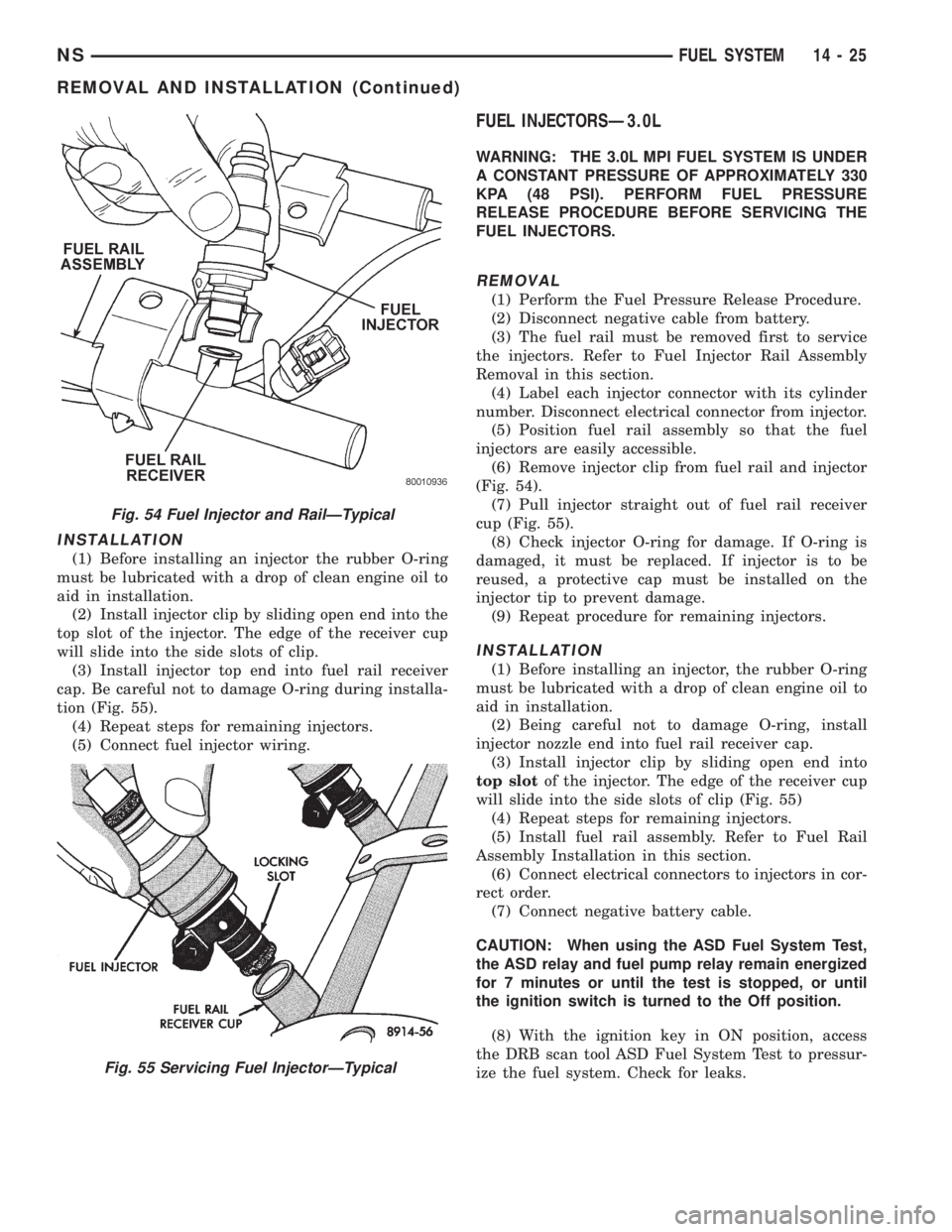
injectors are easily accessible (Fig. 54).
(3) Rotate injector and pull injector out of fuel rail.
The clip will stay on the injector.
(4) Check injector O-ring for damage. If O-ring is
damaged, it must be replaced. If injector is reused, a
protective cap must be installed on the injector tip to
prevent damage. Replace the injector clip if it is dam-
aged.
(5) Repeat for remaining injectors.
Fig. 52 Camshaft Position Sensor Connector
Fig. 53 Fuel Rail Removal
14 - 24 FUEL SYSTEMNS
REMOVAL AND INSTALLATION (Continued)
Page 1319 of 1938
INSTALLATION
(1) Before installing an injector the rubber O-ring
must be lubricated with a drop of clean engine oil to
aid in installation.
(2) Install injector clip by sliding open end into the
top slot of the injector. The edge of the receiver cup
will slide into the side slots of clip.
(3) Install injector top end into fuel rail receiver
cap. Be careful not to damage O-ring during installa-
tion (Fig. 55).
(4) Repeat steps for remaining injectors.
(5) Connect fuel injector wiring.
FUEL INJECTORSÐ3.0L
WARNING: THE 3.0L MPI FUEL SYSTEM IS UNDER
A CONSTANT PRESSURE OF APPROXIMATELY 330
KPA (48 PSI). PERFORM FUEL PRESSURE
RELEASE PROCEDURE BEFORE SERVICING THE
FUEL INJECTORS.
REMOVAL
(1) Perform the Fuel Pressure Release Procedure.
(2) Disconnect negative cable from battery.
(3) The fuel rail must be removed first to service
the injectors. Refer to Fuel Injector Rail Assembly
Removal in this section.
(4) Label each injector connector with its cylinder
number. Disconnect electrical connector from injector.
(5) Position fuel rail assembly so that the fuel
injectors are easily accessible.
(6) Remove injector clip from fuel rail and injector
(Fig. 54).
(7) Pull injector straight out of fuel rail receiver
cup (Fig. 55).
(8) Check injector O-ring for damage. If O-ring is
damaged, it must be replaced. If injector is to be
reused, a protective cap must be installed on the
injector tip to prevent damage.
(9) Repeat procedure for remaining injectors.
INSTALLATION
(1) Before installing an injector, the rubber O-ring
must be lubricated with a drop of clean engine oil to
aid in installation.
(2) Being careful not to damage O-ring, install
injector nozzle end into fuel rail receiver cap.
(3) Install injector clip by sliding open end into
top slotof the injector. The edge of the receiver cup
will slide into the side slots of clip (Fig. 55)
(4) Repeat steps for remaining injectors.
(5) Install fuel rail assembly. Refer to Fuel Rail
Assembly Installation in this section.
(6) Connect electrical connectors to injectors in cor-
rect order.
(7) Connect negative battery cable.
CAUTION: When using the ASD Fuel System Test,
the ASD relay and fuel pump relay remain energized
for 7 minutes or until the test is stopped, or until
the ignition switch is turned to the Off position.
(8) With the ignition key in ON position, access
the DRB scan tool ASD Fuel System Test to pressur-
ize the fuel system. Check for leaks.
Fig. 54 Fuel Injector and RailÐTypical
Fig. 55 Servicing Fuel InjectorÐTypical
NSFUEL SYSTEM 14 - 25
REMOVAL AND INSTALLATION (Continued)
Page 1324 of 1938
THROTTLE BODY....................... 64
THROTTLE POSITION SENSOR............ 65
UPSTREAM OXYGEN SENSOR............. 68
SPECIFICATIONS
TORQUE.............................. 72SPECIAL TOOLS
FUEL................................. 72
GENERAL INFORMATION
INTRODUCTION
All engines used in this section have a sequential
Multi-Port Electronic Fuel Injection system. The MPI
system is computer regulated and provides precise
air/fuel ratios for all driving conditions. The Power-
train Control Module (PCM) operates the fuel injec-
tion system.
The PCM regulates:
²Ignition timing
²Air/fuel ratio
²Emission control devices
²Cooling fan
²Charging system
²Idle speed
²Vehicle speed control
Various sensors provide the inputs necessary for
the PCM to correctly operate these systems. In addi-
tion to the sensors, various switches also provide
inputs to the PCM.
All inputs to the PCM are converted into signals.
The PCM can adapt its programming to meet chang-
ing operating conditions.
Fuel is injected into the intake port above the
intake valve in precise metered amounts through
electrically operated injectors. The PCM fires the
injectors in a specific sequence. Under most operat-
ing conditions, the PCM maintains an air fuel ratio
of 14.7 parts air to 1 part fuel by constantly adjust-
ing injector pulse width. Injector pulse width is the
length of time the injector is open.
The PCM adjusts injector pulse width by opening
and closing the ground path to the injector. Engine
RPM (speed) and manifold absolute pressure (air
density) are the primary inputs that determine injec-
tor pulse width.
MODES OF OPERATION
As input signals to the PCM change, the PCM
adjusts its response to output devices. For example,
the PCM must calculate a different injector pulse
width and ignition timing for idle than it does for
Wide Open Throttle (WOT). There are several differ-
ent modes of operation that determine how the PCM
responds to the various input signals.
There are two different areas of operation, OPEN
LOOP and CLOSED LOOP.
During OPEN LOOP modes the PCM receives
input signals and responds according to preset PCMprogramming. Input from the oxygen (O2S) sensor is
not monitored during OPEN LOOP modes.
During CLOSED LOOP modes the PCM does mon-
itor the O2S sensor input. This input indicates to the
PCM whether or not the calculated injector pulse
width results in the ideal air/fuel ratio of 14.7 parts
air to 1 part fuel. By monitoring the exhaust oxygen
content through the O2S sensor, the PCM can fine
tune the injector pulse width. Fine tuning injector
pulse width allows the PCM to achieve optimum fuel
economy combined with low emissions.
The multi-port fuel injection system has the follow-
ing modes of operation:
²Ignition switch ON (zero RPM)
²Engine start-up
²Engine warm-up
²Cruise (Idle)
²Acceleration
²Deceleration
²Wide Open Throttle
²Ignition switch OFF
The engine start-up (crank), engine warm-up, and
wide open throttle modes are OPEN LOOP modes.
Under most operating conditions, the acceleration,
deceleration, and cruise modes,with the engine at
operating temperatureare CLOSED LOOP modes.
IGNITION SWITCH ON (ZERO RPM) MODE
When the multi-port fuel injection system is acti-
vated by the ignition switch, the following actions
occur:
²The PCM determines atmospheric air pressure
from the MAP sensor input to determine basic fuel
strategy.
²The PCM monitors the coolant temperature sen-
sor and throttle position sensor input. The PCM mod-
ifies fuel strategy based on this input.
When the key is in the ON position and the engine
is not running (zero rpm), the Automatic Shutdown
(ASD) relay and fuel pump relay are not energized.
Therefore battery voltage is not supplied to the fuel
pump, ignition coil, fuel injectors or oxygen sensor
heating element.
ENGINE START-UP MODE
This is an OPEN LOOP mode. The following
actions occur when the starter motor is engaged.
If the PCM receives the camshaft position sensor
and crankshaft position sensor signals, it energizes
the ASD relay and fuel pump relay. These relays sup-
ply battery voltage to the fuel pump, fuel injectors,
14 - 30 FUEL SYSTEMNS
SPECIFICATIONS (Continued)
Page 1376 of 1938
FUEL HEATER
The fuel heater is used to prevent diesel fuel from
waxing during cold weather operation. The fuel
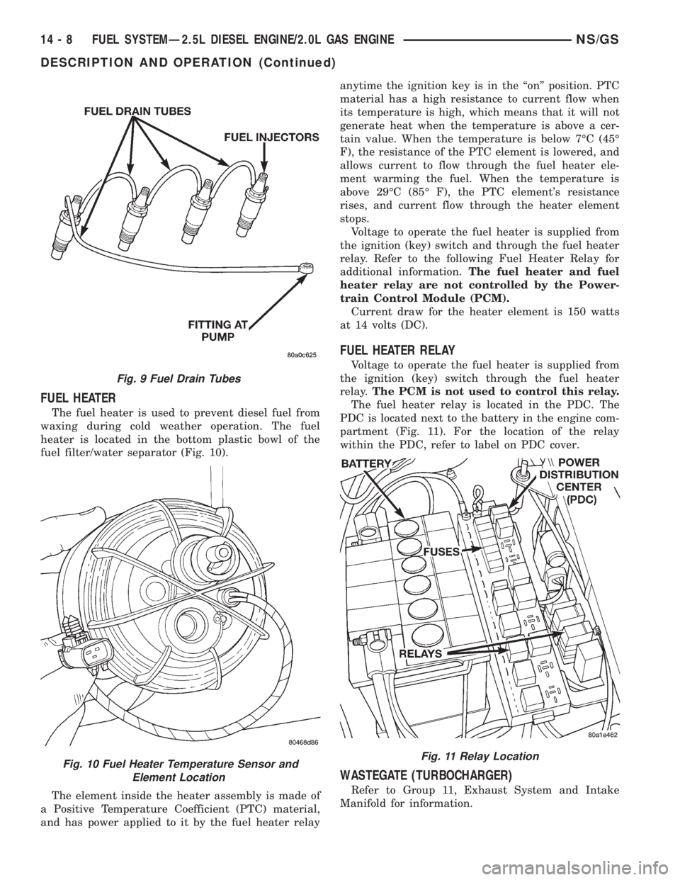
heater is located in the bottom plastic bowl of the
fuel filter/water separator (Fig. 10).
The element inside the heater assembly is made of
a Positive Temperature Coefficient (PTC) material,
and has power applied to it by the fuel heater relayanytime the ignition key is in the ªonº position. PTC
material has a high resistance to current flow when
its temperature is high, which means that it will not
generate heat when the temperature is above a cer-
tain value. When the temperature is below 7ÉC (45É
F), the resistance of the PTC element is lowered, and
allows current to flow through the fuel heater ele-
ment warming the fuel. When the temperature is
above 29ÉC (85É F), the PTC element's resistance
rises, and current flow through the heater element
stops.
Voltage to operate the fuel heater is supplied from
the ignition (key) switch and through the fuel heater
relay. Refer to the following Fuel Heater Relay for
additional information.The fuel heater and fuel
heater relay are not controlled by the Power-
train Control Module (PCM).
Current draw for the heater element is 150 watts
at 14 volts (DC).
FUEL HEATER RELAY
Voltage to operate the fuel heater is supplied from
the ignition (key) switch through the fuel heater
relay.The PCM is not used to control this relay.
The fuel heater relay is located in the PDC. The
PDC is located next to the battery in the engine com-
partment (Fig. 11). For the location of the relay
within the PDC, refer to label on PDC cover.
WASTEGATE (TURBOCHARGER)
Refer to Group 11, Exhaust System and Intake
Manifold for information.
Fig. 9 Fuel Drain Tubes
Fig. 10 Fuel Heater Temperature Sensor and
Element LocationFig. 11 Relay Location
14 - 8 FUEL SYSTEMÐ2.5L DIESEL ENGINE/2.0L GAS ENGINENS/GS
DESCRIPTION AND OPERATION (Continued)
Page 1381 of 1938
A defective fuel injection pump, defective fuel tim-
ing solenoid or misadjusted mechanical pump timing
can cause starting problems or prevent the engine
from revving up. It can also cause:
²Engine surge at idle
²Rough idle (warm engine)
²Low power
²Excessive fuel consumption
²Poor performance
²Low power
²Black smoke from the exhaust
²Blue or white fog like exhaust
²Incorrect idle or maximum speed
The electronically controlled fuel pump has no
mechanical governor like older mechanically con-
trolled fuel pumps. Do not remove the top cover of
the fuel pump, or the screws fastening the wiring
pigtail to the side of the pump.The warranty of
the injection pump and the engine may be void
if those seals have been removed or tampered
with.
FUEL SUPPLY RESTRICTIONS
LOW±PRESSURE LINES
Restricted or Plugged supply lines or fuel filter can
cause a timing fault that will cause the PCM to oper-
ate the engine in a ªLimp Homeº mode. See the
introduction of the Fuel Injection System in this
group for more information on the Limp Home mode.
Fuel supply line restrictions can cause starting prob-
lems and prevent the engine from revving up. The
starting problems include; low power and blue or
white fog like exhaust. Test all fuel supply lines for
restrictions or blockage. Flush or replace as neces-
sary. Bleed the fuel system of air once a fuel supply
line has been replaced. Refer to the Air Bleed Proce-
dure section of this group for procedures.
HIGH±PRESSURE LINES
Restricted (kinked or bent) high±pressure lines can
cause starting problems, poor engine performance
and black smoke from exhaust.
Examine all high±pressure lines for any damage.
Each radius on each high±pressure line must be
smooth and free of any bends or kinks.
Replace damaged, restricted or leaking high±pres-
sure fuel lines with the correct replacement line.
CAUTION: The high±pressure fuel lines must be
clamped securely in place in the holders. The lines
cannot contact each other or other components. Do
not attempt to weld high±pressure fuel lines or to
repair lines that are damaged. Only use the recom-
mended lines when replacement of high±pressure
fuel line is necessary.
FUEL SHUTDOWN SOLENOID TEST
Since diesel fuel injection does not use spark plugs
to start combustion, the only way to stop the engine
is to cut off the fuel supply. This is done with the
Fuel Shutdown Solenoid. If the engine cranks, but
refuses to start, it may be caused by a defective fuel
shutdown solenoid.
The fuel shutdown solenoid is not controlled
or operated by the PCM.Voltage to operate the
solenoid is supplied from the ignition (key) switch.
NOTE: Although the fuel shutdown solenoid is not
operated by the PCM, if the Fuel Shutdown Solenoid
has been disconnected, and the key turned on, the
PCM will sense that the solenoid is not in the circuit,
and will switch to a ªLimp Homeº mode. After recon-
necting the solenoid, the PCM will have to be reset
by clearing the codes with the DRBIII scan tool, or
disconnecting the vehicle's battery for several min-
utes. The DRBIII scan tool is the preferred method
for resetting the PCM. Refer to the 1998 GS 2.5L Die-
sel Powertrain Diagnostic Manual for procedure.
The fuel shutdown (shut±off) solenoid is used to
electrically shut off the diesel fuel supply to the high-
±pressure fuel injection pump. The solenoid is
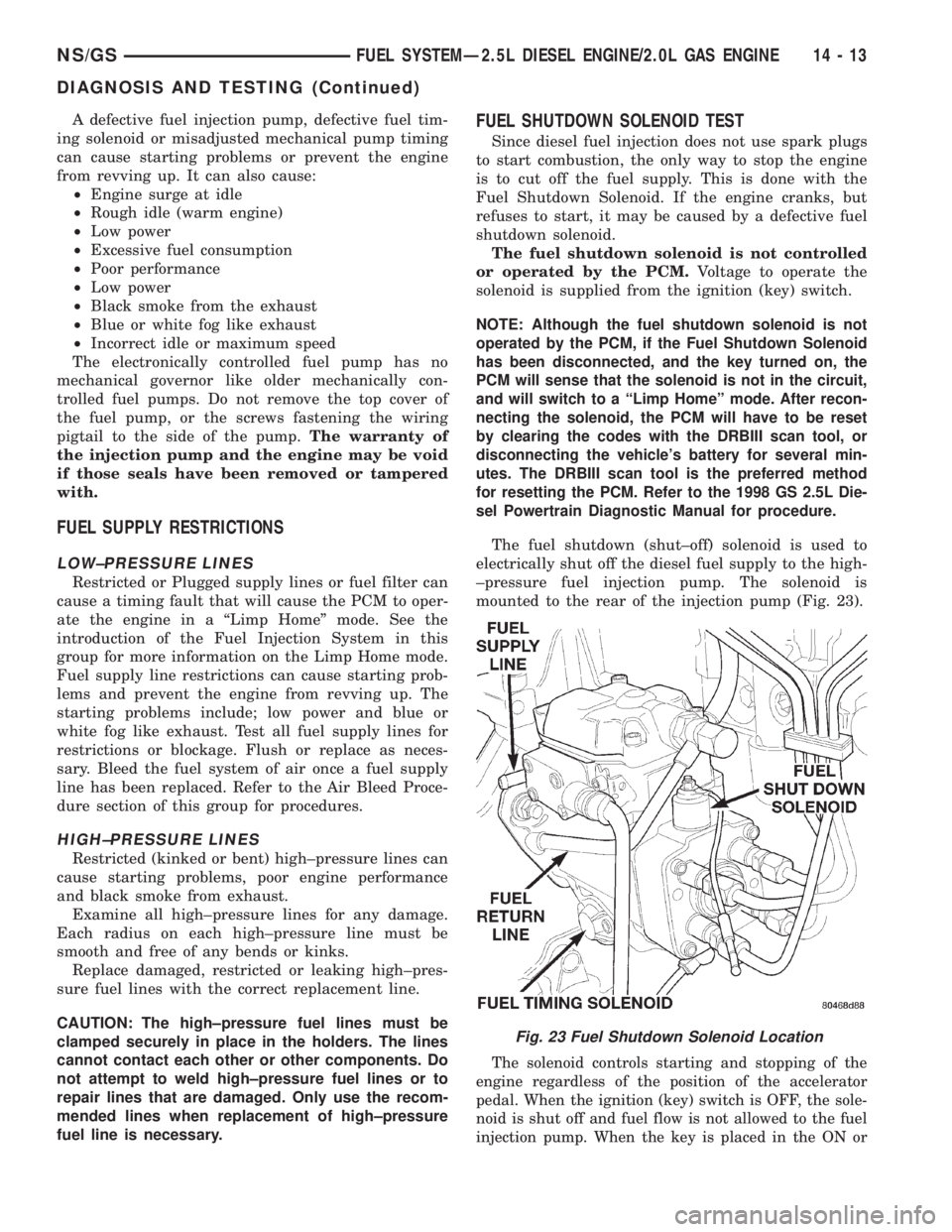
mounted to the rear of the injection pump (Fig. 23).
The solenoid controls starting and stopping of the
engine regardless of the position of the accelerator
pedal. When the ignition (key) switch is OFF, the sole-
noid is shut off and fuel flow is not allowed to the fuel
injection pump. When the key is placed in the ON or
Fig. 23 Fuel Shutdown Solenoid Location
NS/GSFUEL SYSTEMÐ2.5L DIESEL ENGINE/2.0L GAS ENGINE 14 - 13
DIAGNOSIS AND TESTING (Continued)
Page 1411 of 1938
FUEL INJECTION SYSTEMÐ2.5L DIESEL ENGINE
INDEX
page page
GENERAL INFORMATION
INTRODUCTION....................... 43
DESCRIPTION AND OPERATION
AIR CONDITIONING (A/C) CONTROLSÐ
PCM INPUTS........................ 47
AIR CONDITIONING RELAYÐPCM OUTPUT . . 48
BATTERY VOLTAGEÐPCM INPUT.......... 45
BOOST PRESSURE SENSOR............. 45
BRAKE SWITCHÐPCM INPUT............. 47
DATA LINK CONNECTORÐ
PCM INPUT AND OUTPUT.............. 47
DIESEL PCM RELAYÐPCM INPUT......... 48
ENGINE COOLANT GAUGEÐPCM OUTPUT . . 48
ENGINE COOLANT TEMPERATURE SENSORÐ
PCM INPUT......................... 46
ENGINE OIL PRESSURE GAUGEÐ
PCM OUTPUT........................ 48
ENGINE SPEED SENSORÐPCM INPUT..... 46
EXHAUST GAS RECIRCULATION (EGR)
SOLENOIDÐPCM OUTPUT............. 50
FIVE VOLT POWERÐPCM OUTPUT........ 48
FUEL INJECTOR SENSORÐGROUND...... 46
FUEL TIMING SOLENOIDÐPCM OUTPUT.... 48
GLOW PLUG LAMPÐPCM OUTPUT........ 48
GLOW PLUG RELAYÐPCM OUTPUT....... 49
GLOW PLUGS......................... 49
IGNITION CIRCUIT SENSEÐPCM INPUT.... 45
NEEDLE MOVEMENT OR INSTRUMENTED
FIRST INJECTORÐPCM INPUT.......... 45
POWER GROUND...................... 45
POWERTRAIN CONTROL MODULE (PCM) . . . 44
SENSOR RETURNÐPCM INPUT (ANALOG
GROUND)........................... 45SIGNAL GROUNDÐPCM INPUT........... 45
SPEED CONTROLÐPCM INPUTS.......... 48
SPEED CONTROLÐPCM OUTPUTS........ 48
START SIGNALÐPCM INPUT............. 45
TACHOMETERÐPCM OUTPUT............ 49
VEHICLE SPEED SENSORÐPCM INPUT.... 47
VEHICLE THEFT ALARM................. 45
DIAGNOSIS AND TESTING
BOOST PRESSURE SENSOR............. 53
DIAGNOSTIC TROUBLE CODES........... 53
DIESEL DIAGNOSTICS.................. 50
DIESEL PCM RELAY TEST............... 50
ENGINE COOLANT TEMPERATURE
SENSOR TEST....................... 50
ENGINE SPEED SENSOR TEST........... 50
GLOW PLUG RELAY TEST............... 51
GLOW PLUG TEST..................... 51
RELAYSÐOPERATION/TESTING........... 52
VEHICLE SPEED SENSOR TEST........... 53
REMOVAL AND INSTALLATION
A/C CLUTCH RELAY.................... 53
DIESEL PCM RELAY.................... 53
ENGINE COOLANT TEMPERATURE
SENSOR............................ 54
ENGINE SPEED SENSOR................ 53
GLOW PLUG RELAY.................... 55
GLOW PLUGS......................... 54
POWERTRAIN CONTROL MODULE (PCM) . . . 55
VEHICLE SPEED SENSOR............... 55
SPECIFICATIONS
GLOW PLUG CURRENT DRAW............ 56
TORQUE CHARTÐ2.5L DIESEL............ 57
GENERAL INFORMATION
INTRODUCTION
This section will cover components either regulated
or controlled by the Powertrain Control Module
(PCM). The fuel heater relay, fuel heater and fuel
gauge are not operated by the PCM. These compo-
nents are controlled by the ignition (key) switch. All
other fuel system electrical components necessary to
operate the engine are controlled or regulated by the
PCM. Refer to the following PCM description for
more information.
Certain fuel system component failures may cause
a no start, or prevent the engine from running. It is
important to know that the PCM has a featurewhere, if possible, it will ignore the failed sensor, set
a code related to the sensor, and operate the engine
in a ªLimp Homeº mode. When the PCM is operating
in a ªLimp Homeº mode, the Diesel Glow Plug lamp
on the instrument panel will be constantly illumi-
nated, and the engine will most likely have a notice-
able loss of performance. An example of this would be
an Accelerator Pedal Position Sensor failure, and in
that situation, the engine would run at a constant
1100 RPM, regardless of the actual position of the
pedal. This is the most extreme of the three ªLimp
Homeº modes.
In addition to indicating that the glow plugs are
hot enough to start combustion, the Glow Plug Lamp
is also used in the diagnosis of the PCM, and when
NS/GSFUEL SYSTEMÐ2.5L DIESEL ENGINE/2.0L GAS ENGINE 14 - 43
Page 1412 of 1938
illuminated constantly, it usually indicates a problem
has been detected somewhere within the fuel system.
The DRBIII scan tool is the best method for commu-
nicating with the PCM to diagnose faults within the
system.
DESCRIPTION AND OPERATION
POWERTRAIN CONTROL MODULE (PCM)
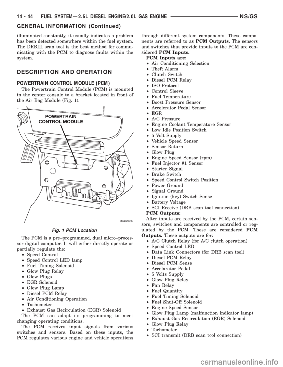
The Powertrain Control Module (PCM) is mounted
in the center consule to a bracket located in front of
the Air Bag Module (Fig. 1).
The PCM is a pre±programmed, dual micro±proces-
sor digital computer. It will either directly operate or
partially regulate the:
²Speed Control
²Speed Control LED lamp
²Fuel Timing Solenoid
²Glow Plug Relay
²Glow Plugs
²EGR Solenoid
²Glow Plug Lamp
²Diesel PCM Relay
²Air Conditioning Operation
²Tachometer
²Exhaust Gas Recirculation (EGR) Solenoid
The PCM can adapt its programming to meet
changing operating conditions.
The PCM receives input signals from various
switches and sensors. Based on these inputs, the
PCM regulates various engine and vehicle operationsthrough different system components. These compo-
nents are referred to asPCM Outputs.The sensors
and switches that provide inputs to the PCM are con-
sideredPCM Inputs.
PCM Inputs are:
²Air Conditioning Selection
²Theft Alarm
²Clutch Switch
²Diesel PCM Relay
²ISO-Protocol
²Control Sleeve
²Fuel Temperature
²Boost Pressure Sensor
²Accelerator Pedal Sensor
²EGR
²A/C Pressure
²Engine Coolant Temperature Sensor
²Low Idle Position Switch
²5 Volt Supply
²Vehicle Speed Sensor
²Sensor Return
²Glow Plug
²Engine Speed Sensor (rpm)
²Fuel Injector #1 Sensor
²Starter Signal
²Brake Switch
²Speed Control Switch Position
²Power Ground
²Signal Ground
²Ignition (key) Switch Sense
²Battery Voltage
²SCI Receive (DRB scan tool connection)
PCM Outputs:
After inputs are received by the PCM, certain sen-
sors, switches and components are controlled or reg-
ulated by the PCM. These are consideredPCM
Outputs.These outputs are for:
²A/C Clutch Relay (for A/C clutch operation)
²Speed Control LED
²Data Link Connectors (for DRB scan tool)
²Diesel PCM Relay
²Diesel PCM Sense
²Accelarator Pedal
²5 Volts Supply
²Glow Plug Relay
²Fan Relay
²Fuel Quantity
²Fuel Timing Solenoid
²Fuel Shut-Off Solenoid
²Engine Speed Sensor
²Glow Plug Lamp (malfunction indicator lamp)
²Exhaust Gas Recirculation (EGR) Solenoid
²Glow Plug Relay
²Tachometer
²SCI transmit (DRB scan tool connection)
Fig. 1 PCM Location
14 - 44 FUEL SYSTEMÐ2.5L DIESEL ENGINE/2.0L GAS ENGINENS/GS
GENERAL INFORMATION (Continued)
Page 1413 of 1938
BOOST PRESSURE SENSOR
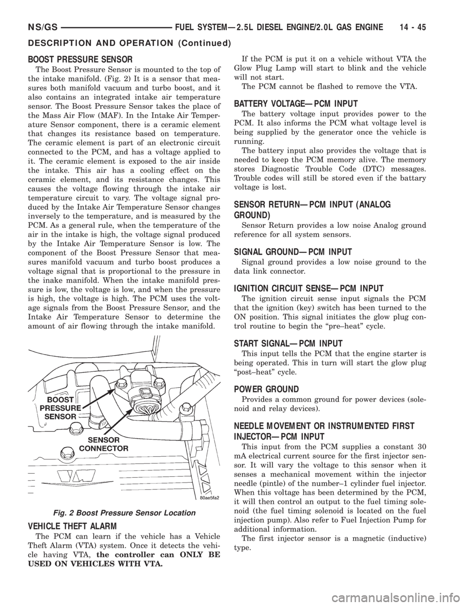
The Boost Pressure Sensor is mounted to the top of
the intake manifold. (Fig. 2) It is a sensor that mea-
sures both manifold vacuum and turbo boost, and it
also contains an integrated intake air temperature
sensor. The Boost Pressure Sensor takes the place of
the Mass Air Flow (MAF). In the Intake Air Temper-
ature Sensor component, there is a ceramic element
that changes its resistance based on temperature.
The ceramic element is part of an electronic circuit
connected to the PCM, and has a voltage applied to
it. The ceramic element is exposed to the air inside
the intake. This air has a cooling effect on the
ceramic element, and its resistance changes. This
causes the voltage flowing through the intake air
temperature circuit to vary. The voltage signal pro-
duced by the Intake Air Temperature Sensor changes
inversely to the temperature, and is measured by the
PCM. As a general rule, when the temperature of the
air in the intake is high, the voltage signal produced
by the Intake Air Temperature Sensor is low. The
component of the Boost Pressure Sensor that mea-
sures manifold vacuum and turbo boost produces a
voltage signal that is proportional to the pressure in
the inake manifold. When the intake manifold pres-
sure is low, the voltage is low, and when the pressure
is high, the voltage is high. The PCM uses the volt-
age signals from the Boost Pressure Sensor, and the
Intake Air Temperature Sensor to determine the
amount of air flowing through the intake manifold.
VEHICLE THEFT ALARM
The PCM can learn if the vehicle has a Vehicle
Theft Alarm (VTA) system. Once it detects the vehi-
cle having VTA,the controller can ONLY BE
USED ON VEHICLES WITH VTA.If the PCM is put it on a vehicle without VTA the
Glow Plug Lamp will start to blink and the vehicle
will not start.
The PCM cannot be flashed to remove the VTA.
BATTERY VOLTAGEÐPCM INPUT
The battery voltage input provides power to the
PCM. It also informs the PCM what voltage level is
being supplied by the generator once the vehicle is
running.
The battery input also provides the voltage that is
needed to keep the PCM memory alive. The memory
stores Diagnostic Trouble Code (DTC) messages.
Trouble codes will still be stored even if the battary
voltage is lost.
SENSOR RETURNÐPCM INPUT (ANALOG
GROUND)
Sensor Return provides a low noise Analog ground
reference for all system sensors.
SIGNAL GROUNDÐPCM INPUT
Signal ground provides a low noise ground to the
data link connector.
IGNITION CIRCUIT SENSEÐPCM INPUT
The ignition circuit sense input signals the PCM
that the ignition (key) switch has been turned to the
ON position. This signal initiates the glow plug con-
trol routine to begin the ªpre±heatº cycle.
START SIGNALÐPCM INPUT
This input tells the PCM that the engine starter is
being operated. This in turn will start the glow plug
ªpost±heatº cycle.
POWER GROUND
Provides a common ground for power devices (sole-
noid and relay devices).
NEEDLE MOVEMENT OR INSTRUMENTED FIRST
INJECTORÐPCM INPUT
This input from the PCM supplies a constant 30
mA electrical current source for the first injector sen-
sor. It will vary the voltage to this sensor when it
senses a mechanical movement within the injector
needle (pintle) of the number±1 cylinder fuel injector.
When this voltage has been determined by the PCM,
it will then control an output to the fuel timing sole-
noid (the fuel timing solenoid is located on the fuel
injection pump). Also refer to Fuel Injection Pump for
additional information.
The first injector sensor is a magnetic (inductive)
type.
Fig. 2 Boost Pressure Sensor Location
NS/GSFUEL SYSTEMÐ2.5L DIESEL ENGINE/2.0L GAS ENGINE 14 - 45
DESCRIPTION AND OPERATION (Continued)