1996 CHRYSLER VOYAGER key battery
[x] Cancel search: key batteryPage 581 of 1938

8W-10 POWER DISTRIBUTION
Component Page
A/C Compressor Clutch........................8W-10-29
A/C Compressor Clutch Relay................8W-10-10, 25, 29
Airbag Control Module........................8W-10-35
Automatic Shut Down Relay....................8W-10-9, 23
Battery.............................8W-10-8, 27, 28
Body Control Module...........8W-10-11, 14, 16, 17, 19, 21, 30, 32
BS15..................................8W-10-33
BS16..................................8W-10-34
BS19..................................8W-10-30
BS33..................................8W-10-25
Center Dome Lamp..........................8W-10-21
Cigar/Accessory Relay......................8W-10-10, 31
Clockspring..............................8W-10-30
Combination Flasher/DRL Module................8W-10-29, 32
Controller Anti-Lock Brake....................8W-10-15, 29
Courtesy Lamp Relay.........................8W-10-21
Crank Case Heater..........................8W-10-27
CS01..................................8W-10-21
CS02..................................8W-10-20
CS1 ..................................8W-10-21
Data Link Connector.........................8W-10-11
Diesel Power Relay.......................8W-10-9, 25, 29
Door Lock Relay............................8W-10-13
Door Unlock Relay..........................8W-10-13
Downstream Heated Oxygen Sensor.................8W-10-23
Driver Door Courtesy Lamp.....................8W-10-21
Driver Door Unlock Relay......................8W-10-13
Driver Power Mirror.......................8W-10-12, 22
EGR Solenoid.............................8W-10-25
Engine Starter Motor.......................8W-10-8, 16
Engine Starter Motor Relay....................8W-10-8, 16
ES01................................8W-10-27, 28
ES06................................8W-10-25, 29
ES07..................................8W-10-29
ES09..................................8W-10-8
ES11 ................................8W-10-8, 28
ES12..................................8W-10-23
ES26..................................8W-10-8
ES28..................................8W-10-8
ES29................................8W-10-25, 29
ES40..................................8W-10-27
ES99..................................8W-10-24
Fog Lamp Relay............................8W-10-33
Front Blower Motor..........................8W-10-18
Front Blower Motor Relay.....................8W-10-8, 18
Front Cigar Lighter/Power Outlet..................8W-10-31
Front Reading Lamps/Switch.....................8W-10-20
Front Wiper Switch..........................8W-10-19
FS01..................................8W-10-24
FS03..................................8W-10-23
Fuel Heater..............................8W-10-27
Fuel Heater Relay.........................8W-10-9, 27
Fuel Injector No. 1........................8W-10-23, 24
Fuel Injector No. 2........................8W-10-23, 24
Fuel Injector No. 3........................8W-10-23, 24
Fuel Injector No. 4........................8W-10-23, 24
Fuel Injector No. 5..........................8W-10-24
Fuel Injector No. 6..........................8W-10-24
Fuel Pump Module..........................8W-10-25
Fuel Pump Relay..........................8W-10-9, 26
Fuel Tank Module...........................8W-10-26
Fuse 1 (JB)..............................8W-10-17
Fuse 1 (PDC)...........................8W-10-14, 35
Fuse 2 (JB)............................8W-10-11, 16
Fuse 2 (PDC).............................8W-10-35
Fuse 3 (JB)..............................8W-10-17
Fuse 4 (JB)..............................8W-10-17
Fuse 4 (PDC).......................8W-10-10, 32, 33, 34
Fuse 5 (JB)..............................8W-10-17
Fuse 5 (PDC).......................8W-10-10, 32, 33, 34
Fuse 6 (JB)..............................8W-10-16
Fuse 6 (PDC).......................8W-10-10, 32, 33, 34
Fuse 7 (JB)..............................8W-10-12
Fuse 7 (PDC).......................8W-10-10, 32, 33, 34
Fuse 8 (JB)..............................8W-10-16
Fuse 8 (PDC)...........................8W-10-10, 31
Fuse 9 (JB)..............................8W-10-16
Fuse 9 (PDC)...........................8W-10-10, 30
Fuse 10 (JB)..............................8W-10-16
Fuse 10 (PDC)...........................8W-10-10, 29
Fuse 11 (JB)..............................8W-10-14
Fuse 11 (PDC)...........................8W-10-10, 29
Fuse 12 (JB)............................8W-10-14, 18
Fuse 12 (PDC)...........................8W-10-10, 29
Fuse 13 (PDC)...........................8W-10-10, 29
Fuse 15 (PDC)...........................8W-10-9, 28
Fuse 16 (JB)..............................8W-10-27
Fuse 16 (PDC)...........................8W-10-9, 26
Fuse 17 (PDC).......................8W-10-9, 23, 25, 29
Fuse 18 (PDC)...........................8W-10-9, 20Component Page
Fuse 19 (PDC)...........................8W-10-8, 19
Fuse 20 (PDC)...........................8W-10-8, 19
Fuse 21 (PDC)...........................8W-10-8, 18
Fuse 22 (PDC)...........................8W-10-8, 17
Fuse 23 (PDC)...........................8W-10-8, 16
Fuse 24 (PDC)...........................8W-10-8, 15
Fuse 25 (PDC)...........................8W-10-8, 15
Fuse 26 (PDC)...........................8W-10-8, 13
Fuse 27 (PDC)...........................8W-10-8, 12
Fuse 28 (PDC)...........................8W-10-9, 11
Fusible Link A11............................8W-10-8
Fusible Link A54............................8W-10-8
G100................................8W-10-27, 28
G103................................8W-10-27, 28
G200................................8W-10-14, 32
G300............................8W-10-14, 18, 19, 31
Generator............................8W-10-8, 23, 25
Glove Box Lamp............................8W-10-20
Glow Plug Relay..........................8W-10-8, 25
Headlamp Dimmer Switch......................8W-10-32
Headlamp Switch.........................8W-10-21, 34
High Beam Relay.....................8W-10-10, 32, 33, 34
High Note Horn............................8W-10-30
Horn Relay............................8W-10-10, 30
Horn Switch..............................8W-10-30
HS6D S02...............................8W-10-13
Ignition Coil Pack...........................8W-10-23
Ignition Switch........................8W-10-11, 14, 16
Instrument Cluster........................8W-10-11, 14
Junction Block..........8W-10-11, 12, 13, 14, 16, 17, 18, 20, 21, 22,
26, 27, 29, 30, 31, 32, 35
Key-In Halo Lamp..........................8W-10-21
Left Headlamp..........................8W-10-33, 34
Left Headlamp Leveling Motor....................8W-10-34
Left High Headlamp.........................8W-10-33
Left Liftgate Flood Lamp.......................8W-10-21
Left Mid Reading Lamp.....................8W-10-20, 21
Left Rear Reading Lamp.....................8W-10-20, 21
Left Visor/Vanity Mirror Lamps...................8W-10-20
Low Beam Relay.....................8W-10-10, 32, 33, 34
Low Note Horn............................8W-10-30
Memory Seat/Mirror Module.....................8W-10-11
Message Center......................8W-10-11, 14, 33, 34
Name Brand Speaker Relay.....................8W-10-16
Park Lamp Relay..........................8W-10-8, 17
Passenger Door Courtesy Lamp...................8W-10-21
Passenger Power Mirror.....................8W-10-12, 22
Power Distribution Center .8W-10-8, 9, 10, 11, 12, 13, 14, 15, 16, 17, 18, 19,
20, 23, 25, 26, 27, 28, 29, 30, 31, 32, 33, 34, 35
Power Mirror Fold Relay.......................8W-10-22
Power Mirror Switch.........................8W-10-20
Power Mirror Unfold Relay....................8W-10-21, 22
Power Seat Circuit Breaker.....................8W-10-13
Powertrain Control Module............8W-10-16, 23, 25, 26, 27, 29
PTC 1 (JB)......................8W-10-16, 26, 27, 29, 35
PTC 3 (JB)..............................8W-10-13
PTC 7 (JB)............................8W-10-16, 31
PTC 8 (JB)..............................8W-10-16
PTC 9 (JB)..............................8W-10-16
Radiator Fan Relay..........................8W-10-15
Radiator Fan Relay No. 1.......................8W-10-25
Radiator Fan Relay No. 2.....................8W-10-15, 25
Radiator Fan Relay No. 3.....................8W-10-19, 25
Radio..................................8W-10-11
Rear Cigar Lighter/Power Outlet...................8W-10-31
Rear Dome Lamp...........................8W-10-21
Rear Window Defogger........................8W-10-12
Rear Window Defogger Relay.....................8W-10-12
Remote Keyless Entry Module....................8W-10-11
Right Headlamp..........................8W-10-33, 34
Right Headlamp Leveling Motor...................8W-10-34
Right High Headlamp.........................8W-10-33
Right Liftgate Flood Lamp......................8W-10-21
Right Low Headlamp.........................8W-10-33
Right Mid Reading Lamp.....................8W-10-20, 21
Right Rear Reading Lamp....................8W-10-20, 21
Right Visor/Vanity Mirror Lamps..................8W-10-20
Sentry Key Immobilizer Module...................8W-10-20
Stop Lamp Switch...........................8W-10-29
Transmission Control Module..................8W-10-16, 28
Transmission Control Relay....................8W-10-9, 28
Transmission Control Solenoids...................8W-10-28
Universal Garage Door Opener....................8W-10-20
Upstream Heated Oxygen Sensor..................8W-10-23
Vehicle Speed Sensor.......................8W-10-27, 29
Washer Module............................8W-10-13
Wiper High/Low Relay........................8W-10-19
Wiper Module.............................8W-10-19
Wiper On Relay..........................8W-10-8, 19
NS/GS8W - 10 POWER DISTRIBUTION 8W - 10 - 1
Page 643 of 1938

8W-15 GROUND DISTRIBUTION
Component PageA/C Compressor Clutch....................8W-15-2, 3
A/C Heater Control........................8W-15-4
Airbag Control Module......................8W-15-4
All Wheel Drive Solenoid....................8W-15-13
Ash Receiver Lamp........................8W-15-6
Automatic Day/Night Mirror...................8W-15-5
AW4B13..............................8W-15-13
AWS1................................8W-15-13
Battery..............................8W-15-2, 3
Body Control Module.......................8W-15-6
Brake Pressure Switch......................8W-15-8
BS08.................................8W-15-5
BS31.................................8W-15-3
BS40.................................8W-15-3
BS41.................................8W-15-3
Center High Mounted Stop Lamp...............8W-15-14
Cigar/Accessory Relay.......................8W-15-7
Clockspring.............................8W-15-4
Clutch Switch............................8W-15-8
Combination Flasher/DRL Module...............8W-15-6
Controller Anti-Lock Brake....................8W-15-4
Crank Case Heater........................8W-15-3
CS06..............................8W-15-11, 12
Data Link Connector....................8W-15-2, 4, 12
Door Lock Relay..........................8W-15-6
Door Unlock Relay.........................8W-15-6
Downstream Heated Oxygen Sensor..............8W-15-5
Driver Door Arm/Disarm Switch.............8W-15-11, 12
Driver Door Courtesy Lamp...................8W-15-7
Driver Door Lock Switch..................8W-15-11, 12
Driver Door Unlock Relay....................8W-15-6
Driver Heated Seat Back.....................8W-15-9
Driver Heated Seat Cushion...................8W-15-9
Driver Heated Seat Module...................8W-15-9
Driver Heated Seat Switch....................8W-15-9
Driver Power Mirror........................8W-15-4
Driver Power Seat Switch....................8W-15-5
Driver Power Window Switch..................8W-15-7
DS01.................................8W-15-7
EC1C19...............................8W-15-5
Engine Speed Sensor.......................8W-15-3
ES01.................................8W-15-3
ES02.................................8W-15-3
ES11 .................................8W-15-2
ES12.................................8W-15-3
ES18.................................8W-15-2
ES23.................................8W-15-2
ES30.................................8W-15-3
ES31.................................8W-15-3
Front Blower Motor Relay....................8W-15-7
Front Cigar Lighter/Power Outlet...............8W-15-4
Fuel Heater.............................8W-15-3
Fuel Heater Relay.........................8W-15-3
Fuel Tank Module........................8W-15-13
G100................................8W-15-2, 3
G101.................................8W-15-2
G102................................8W-15-2, 3
G103................................8W-15-2, 3
G104.................................8W-15-4
G200.................................8W-15-4
G201.................................8W-15-4
G202.................................8W-15-5
G204.................................8W-15-4
G300...........................8W-15-5, 6, 7, 8, 9
G301............................8W-15-10, 11, 12
G302.................................8W-15-13
G400.................................8W-15-14
Headlamp Dimmer Switch....................8W-15-4
Headlamp Switch........................8W-15-4, 6
Headlamp Washer........................8W-15-10
High Note Horn.......................8W-15-11, 12
Hood Ajar Switch.........................8W-15-10
HS1..................................8W-15-9
HS3..................................8W-15-9
HS5D B09..............................8W-15-9
HS5P B56..............................8W-15-9
Ignition Switch.........................8W-15-4, 6
Instrument Cluster.......................8W-15-4, 6
Junction Block...........................8W-15-6
Key-In Halo Lamp.........................8W-15-6
Left Combination Relay.....................8W-15-13Component PageLeft Door Speaker.........................8W-15-5
Left Front Park/Turn Signal Lamp...............8W-15-7
Left Headlamp...........................8W-15-8
Left Headlamp Leveling Motor.................8W-15-8
Left High Headlamp........................8W-15-8
Left Liftgate Flood Lamp....................8W-15-14
Left Low Headlamp........................8W-15-8
Left Rear Door Ajar Switch...................8W-15-13
Left Rear Lamp Assembly....................8W-15-13
Left Rear Speaker.........................8W-15-5
Left Repeater Lamp........................8W-15-5
Left Speed Control Switch....................8W-15-4
Left Stop/Turn Signal Relay..................8W-15-13
License Lamp...........................8W-15-14
Liftgate Ajar Switch.......................8W-15-14
Liftgate Arm/Disarm Switch..................8W-15-14
Low Coolant Level Switch....................8W-15-3
Low Note Horn..........................8W-15-10
Low Washer Fluid Switch.................8W-15-11, 12
Memory Power Seat Switch..................8W-15-5, 9
Memory Seat/Mirror Module.................8W-15-5, 9
Memory Set Switch........................8W-15-7
Message Center...........................8W-15-6
Name Brand Speaker Relay...................8W-15-6
Needle Movement Sensor.....................8W-15-3
Overhead Console......................8W-15-11, 12
Passenger Door Arm/Disarm Switch.............8W-15-10
Passenger Door Courtesy Lamp.................8W-15-7
Passenger Door Lock Switch..................8W-15-10
Passenger Heated Seat Back...................8W-15-9
Passenger Heated Seat Cushion.................8W-15-9
Passenger Heated Seat Module.................8W-15-9
Passenger Heated Seat Switch.................8W-15-9
Passenger Power Mirror.....................8W-15-4
Passenger Power Seat Switch................8W-15-5, 12
Passenger Power Window Switch................8W-15-7
Power Distribution Center.................8W-15-2, 3, 7
Power Folding Mirror Switch..................8W-15-6
Power Mirror Switch.......................8W-15-6
Powertrain Control Module..................8W-15-2, 3
Radiator Fan Disconnect.....................8W-15-3
Radiator Fan No. 1........................8W-15-2
Radiator Fan No. 2........................8W-15-2
Radiator Fan Relay........................8W-15-2
Radiator Fan Relay No. 1.....................8W-15-3
Radio.................................8W-15-5
Rear Blower Front Control Switch...............8W-15-4
Rear Blower Rear Control Switch...............8W-15-13
Rear Cigar Lighter/Power Outlet...............8W-15-13
Rear Window Defogger.....................8W-15-14
Rear Wiper Motor.........................8W-15-14
Remote Keyless Entry Module..................8W-15-4
RF3E40...............................8W-15-2
RFS2.................................8W-15-2
Right Combination Relay....................8W-15-13
Right Door Speaker........................8W-15-5
Right Front Park/Turn Signal Lamp.............8W-15-10
Right Headlamp..........................8W-15-10
Right Headlamp Leveling Motor................8W-15-10
Right High Headlamp......................8W-15-10
Right Liftgate Flood Lamp...................8W-15-14
Right Low Headlamp......................8W-15-10
Right Rear Door Ajar Switch..................8W-15-13
Right Rear Lamp Assembly...................8W-15-13
Right Rear Speaker........................8W-15-5
Right Repeater Lamp......................8W-15-10
Right Speed Control Switch...................8W-15-4
Right Stop/Turn Signal Relay.................8W-15-13
Seat Belt Switch..........................8W-15-8
Sentry Key Immobilizer Module.................8W-15-4
Stop Lamp Switch.......................8W-15-6, 7
Traction Control Switch......................8W-15-6
Trailer Tow Connector......................8W-15-13
Transmission Control Module..................8W-15-2
Transmission Control Relay...................8W-15-2
Universal Garage Door Opener..............8W-15-11, 12
Upstream Heated Oxygen Sensor................8W-15-2
Vehicle Speed Control Servo...................8W-15-2
Wiper Module............................8W-15-5
Wiper On Relay...........................8W-15-7
NS/GS8W - 15 GROUND DISTRIBUTION 8W - 15 - 1
Page 665 of 1938

8W-30 FUEL/IGNITION SYSTEM
Component Page
A/C Compressor Clutch Relay................8W-30-5, 37
A/C Heater Control....................8W-30-5, 32, 37
A/C Pressure Transducer.............8W-30-10, 16, 24, 38
Accelerator Pedal Position Sensor...............8W-30-38
Airbag Control Module....................8W-30-4, 31
All Wheel Drive Solenoid....................8W-30-20
Automatic Shut Down Relay . . .8W-30-2, 7, 8, 9, 14, 15, 21, 22, 23
AW4B13...............................8W-30-6
AW4B13..............................8W-30-20
AWS1................................8W-30-20
AWS2................................8W-30-20
Back-Up Switch........................8W-30-6, 20
Battery..........................8W-30-2, 3, 29, 32
Body Control Module.............8W-30-4, 6, 20, 31, 36, 39
BS01................................8W-30-39
BS02...............................8W-30-6, 20
BS05...............................8W-30-4, 31
BS06...............................8W-30-4, 31
BS30................................8W-30-36
BS31..............................8W-30-28, 35
BS32................................8W-30-33
BS33................................8W-30-28
BS34..........................8W-30-33, 34, 36, 38
BS40................................8W-30-35
BS41................................8W-30-35
Camshaft Position Sensor..............8W-30-8, 14, 22, 24
Clockspring...........................8W-30-5, 39
Clutch Switch...........................8W-30-39
Compass/Mini-Trip Computer.................8W-30-31
Control Sleeve Sensor......................8W-30-34
Controller Anti-Lock Brake.................8W-30-4, 31
Crank Case Heater........................8W-30-29
Crankshaft Position Sensor...............8W-30-8, 14, 22
Data Link Connector.................8W-30-3, 4, 30, 31
Diesel Power Relay.................8W-30-28, 29, 32, 33
Downstream Heated Oxygen Sensor............8W-30-7, 21
EGR Solenoid.......................8W-30-18, 20, 29
Engine Coolant Temperature Sensor......8W-30-10, 16, 24, 36
Engine Speed Sensor.......................8W-30-35
Engine Starter Motor Relay...............8W-30-6, 20, 28
ES01................................8W-30-29
ES02.............8W-30-8, 10, 11, 14, 16, 17, 22, 24, 25, 29
ES03.....................8W-30-10, 11, 16, 17, 24, 25
ES05...................8W-30-14, 19, 22, 25, 33, 34, 36
ES06..........................8W-30-28, 29, 32, 33
ES07..........................8W-30-2, 18, 20, 26
ES08............................8W-30-17, 19, 25
ES09................................8W-30-37
ES11................................8W-30-2, 3
ES12.................8W-30-2, 7, 8, 9, 14, 15, 21, 22, 23
ES13.................................8W-30-4
ES14.................................8W-30-4
ES17........................8W-30-8, 11, 14, 17, 22
ES18...............................8W-30-7, 21
ES21..................8W-30-7, 8, 10, 11, 14, 16, 17, 24
ES24.................................8W-30-3
ES26................................8W-30-32
ES28................................8W-30-32
ES29................................8W-30-32
ES30................................8W-30-35
ES31................................8W-30-35
ES37................................8W-30-32
ES40................................8W-30-29
ES99.................................8W-30-9
Evap Leak Detection Pump................8W-30-18, 26
Evap/Purge Solenoid..................8W-30-12, 18, 26
Flexible Fuel Sensor.......................8W-30-22
FS01..............................8W-30-16, 23
FS02............................8W-30-16, 22, 24
FS03.................................8W-30-15
Fuel Heater............................8W-30-29
Fuel Heater Relay........................8W-30-29
Fuel Injector No. 1....................8W-30-9, 15, 23
Fuel Injector No. 2....................8W-30-9, 15, 23
Fuel Injector No. 3....................8W-30-9, 15, 23
Fuel Injector No. 4....................8W-30-9, 15, 23
Fuel Injector No. 5........................8W-30-23Component Page
Fuel Injector No. 6........................8W-30-23
Fuel Pump Module......................8W-30-33, 34
Fuel Pump Relay.......................8W-30-6, 20
Fuel Quantity Actuator.....................8W-30-33
Fuel Shutdown Solenoid.....................8W-30-33
Fuel Tank Module.......................8W-30-6, 20
Fuel Temperature Sensor....................8W-30-33
Fuel Timing Solenoid......................8W-30-33
Fuse 6 (JB).............................8W-30-32
Fuse 13 (PDC)...........................8W-30-39
Fuse 16 (PDC).....................8W-30-2, 6, 20, 29
Fuse 17 (PDC) . .8W-30-2, 7, 8, 9, 14, 15, 21, 22, 23, 28, 29, 32, 33
Fuse 28 (PDC).........................8W-30-3, 30
Fusible Link A0..........................8W-30-32
G100.............................8W-30-2, 3, 29
G101...............................8W-30-7, 21
G103.............................8W-30-2, 3, 29
G200.............................8W-30-3, 5, 30
G300.................8W-30-7, 13, 19, 21, 27, 28, 35, 39
G301..............................8W-30-30, 35
G302...............................8W-30-6, 20
Generator.......................8W-30-2, 13, 19, 27
Glow Plug Lamp.........................8W-30-32
Glow Plug No. 1..........................8W-30-32
Glow Plug No. 2..........................8W-30-32
Glow Plug No. 3..........................8W-30-32
Glow Plug No. 4..........................8W-30-32
Glow Plug Relay.........................8W-30-32
Idle Air Control Motor.................8W-30-12, 18, 26
Ignition Coil Pack.....................8W-30-8, 14, 22
Instrument Cluster......................8W-30-4, 31
Intake Air Temperature Sensor................8W-30-17
Intake Air Temperature/Manifold Absolute
Pressure Sensor.......................8W-30-10
Junction Block............8W-30-2, 3, 6, 13, 18, 19, 20, 26,
27, 28, 29, 30, 32, 36
Knock Sensor.......................8W-30-10, 16, 24
Left Front Park/Turn Signal Lamp..............8W-30-39
Left Headlamp Leveling Motor.................8W-30-39
Left Speed Control Switch..................8W-30-5, 39
Manifold Absolute Pressure Sensor............8W-30-16, 24
Memory Seat/Mirror Module................8W-30-3, 30
Message Center...................8W-30-13, 19, 27, 32
Needle Movement Sensor....................8W-30-35
Overhead Console.......................8W-30-4, 31
Power Distribution Center .8W-30-2, 3, 5, 6, 7, 8, 9, 14, 15, 18, 20,
21, 22, 23, 26, 28, 29, 30, 32, 33, 36, 37, 39
Powertrain Control Module...................8W-30-10
Powertrain Control Module...................8W-30-11
Powertrain Control Module...................8W-30-12
Powertrain Control Module...................8W-30-13
Powertrain Control Module...................8W-30-8
Powertrain Control Module...................8W-30-9
Powertrain Control Module .8W-30-2, 3, 4, 5, 6, 7, 8, 9, 14, 15, 16,
17, 18, 19, 20, 21, 22, 23, 24, 25, 26,
27, 28, 29, 30, 32, 33, 34, 35, 36, 37, 38, 39
PS01...............................8W-30-4, 31
PS02...............................8W-30-4, 31
PTC 1 (JB)..............8W-30-2, 6, 18, 20, 26, 28, 29, 36
Radiator Fan Relay........................8W-30-5
Radiator Fan Relay No. 1....................8W-30-37
Radiator Fan Relay No. 2....................8W-30-37
Radiator Fan Relay No. 3....................8W-30-37
Radio.............................8W-30-3, 4, 30
Right Speed Control Switch.................8W-30-5, 39
Sentry Key Immobilizer Module.................8W-30-4
Service Engine Soon Lamp..............8W-30-13, 19, 27
Stop Lamp Switch.................8W-30-13, 19, 27, 39
Throttle Position Sensor................8W-30-11, 17, 25
Transmission Control Module.......8W-30-3, 4, 17, 19, 25, 27
Transmission Range Sensor..........8W-30-6, 19, 20, 27, 34
Turbo Boost Pressure Sensor..................8W-30-34
Upstream Heated Oxygen Sensor.............8W-30-7, 21
Vacuum Solenoid.........................8W-30-27
Vehicle Speed Control Servo..............8W-30-13, 19, 27
Vehicle Speed Sensor..................8W-30-11, 17, 36
Vent Solenoid...........................8W-30-27
NS/GS8W - 30 FUEL/IGNITION SYSTEM 8W - 30 - 1
Page 769 of 1938

8W-45 BODY CONTROL MODULE
Component Page
A/C Heater Control..................8W-45-5, 6
Ash Receiver Lamp....................8W-45-5
Automatic Day/Night Mirror.............8W-45-8
Back-Up Switch.......................8W-45-9
Battery.............................8W-45-9
Body Control Module . .8W-45-2, 3, 4, 5, 6, 7, 8, 9, 10
BS02...............................8W-45-9
BS10...............................8W-45-8
BS30...............................8W-45-9
Clockspring..........................8W-45-3
Combination Flasher/DRL Module........8W-45-5
Controller Anti-Lock Brake..............8W-45-6
CS03...............................8W-45-8
Data Link Connector...................8W-45-3
Door Lock Relay......................8W-45-7
Door Unlock Relay....................8W-45-7
Driver Door Ajar Switch................8W-45-7
Driver Door Arm/Disarm Switch..........8W-45-8
Driver Door Lock Switch..............8W-45-6, 8
Driver Door Unlock Relay...............8W-45-7
Driver Power Mirror..................8W-45-10
Driver Power Window Switch............8W-45-6
Engine Coolant Temperature Sensor.......8W-45-9
Engine Oil Pressure Switch..............8W-45-7
ES01...............................8W-45-9
ES02...............................8W-45-9
Front Cigar Lighter/Power Outlet.........8W-45-5
Front Reading Lamps/Switch............8W-45-8
Front Wiper Switch....................8W-45-4
Fuel Tank Module...................8W-45-7, 9
Fuse 1 (JB)..........................8W-45-3
Fuse 2 (JB)..........................8W-45-2
Fuse 3 (JB)..........................8W-45-3
Fuse 6 (JB)..........................8W-45-2
Fuse 19 (PDC)........................8W-45-4
Fuse 22 (PDC)........................8W-45-3
Fuse 28 (PDC)........................8W-45-2
G100...............................8W-45-9
G103...............................8W-45-9
G300............................8W-45-2, 10
G302...............................8W-45-9
Glove Box Lamp......................8W-45-8
Headlamp Dimmer Switch..............8W-45-5
Headlamp Switch...............8W-45-2, 3, 4, 5
Hood Ajar Switch.....................8W-45-7
Horn Relay..........................8W-45-3
HVAC Control........................8W-45-6
Ignition Switch.....................8W-45-2, 5
Instrument Cluster....................8W-45-5
Junction Block...........8W-45-2, 3, 4, 5, 6, 7, 10
Key-In Halo Lamp....................8W-45-10Component Page
Left Mid Reading Lamp................8W-45-8
Left Rear Door Ajar Switch..............8W-45-8
Left Rear Reading Lamp................8W-45-8
Left Visor/Vanity Mirror Lamps..........8W-45-8
Liftgate Ajar Switch...................8W-45-7
Liftgate Arm/Disarm Switch.............8W-45-6
LJ01 B17..........................8W-45-4, 6
Low Beam Relay......................8W-45-5
Low Coolant Level Switch...............8W-45-9
Low Washer Fluid Switch...............8W-45-3
Memory Seat/Mirror Module...........8W-45-2, 6
Message Center.....................8W-45-5, 6
Park Lamp Relay.....................8W-45-3
Passenger Door Ajar Switch.............8W-45-7
Passenger Door Arm/Disarm Switch.......8W-45-8
Passenger Door Lock Switch...........8W-45-6, 8
Passenger Power Mirror...............8W-45-10
Passenger Power Window Switch.........8W-45-6
Power Distribution Center...........8W-45-2, 3, 4
Power Folding Mirror Switch...........8W-45-10
Power Mirror Fold Relay...............8W-45-10
Power Mirror Switch...................8W-45-5
Power Mirror Unfold Relay.............8W-45-10
Powertrain Control Module..............8W-45-9
PS01...............................8W-45-3
PS02...............................8W-45-3
PTC 3 (JB)..........................8W-45-7
Radio.............................8W-45-4, 5
Rear Blower Front Control Switch........8W-45-5
Rear Blower Rear Control Switch.........8W-45-6
Rear Washer Motor....................8W-45-4
Rear Wiper Motor.....................8W-45-4
Remote Keyless Entry Module...........8W-45-6
Right Mid Reading Lamp...............8W-45-8
Right Rear Door Ajar Switch.............8W-45-8
Right Rear Reading Lamp...............8W-45-8
Right Visor/Vanity Mirror Lamps.........8W-45-8
Seat Belt Switch......................8W-45-7
Traction Control Switch.................8W-45-5
Universal Garage Door Opener...........8W-45-6
Wiper Module........................8W-45-3
Wiper On Relay.......................8W-45-4
NS/GS8W - 45 BODY CONTROL MODULE 8W - 45 - 1
Page 1270 of 1938

(2) Tighten intake manifold fasteners in the fol-
lowing sequence (Fig. 16). Torque to 23 N´m (200 in.
lbs.). Repeat this procedure until all bolts are at
specified torque.
(3) Install intake manifold center support bracket
bolts (Y bracket):
²Fastener to block 54 N´m (40 ft. lbs.)
²Fastener to intake 28 N´m (250 in. lbs.)
(4) Install fuel hose quick connector fitting to
chassis tubes.Refer to Fuel Hoses, Clamps and
Quick Connect Fittings in Group 14, Fuel Deliv-
ery.Push the fitting onto the chassis tube until it
clicks into place. Pull on the fitting to ensure com-
plete insertion.
(5) Reverse removal procedures 2 through 12 for
installation.
CAUTION: When using the ASD Fuel System Test,
the ASD relay and fuel pump relay remain energized
for 7 minutes or until the test is stopped, or until
the ignition switch is turned to the Off position.
(6) With the ignition key in ON position, access
the DRB scan tool ASD Fuel System Test to pressur-
ize the fuel system. Check for leaks.
EXHAUST MANIFOLDÐ2.4L ENGINE
REMOVAL
(1) Raise vehicle and disconnect exhaust pipe from
the exhaust manifold at the flex-joint.
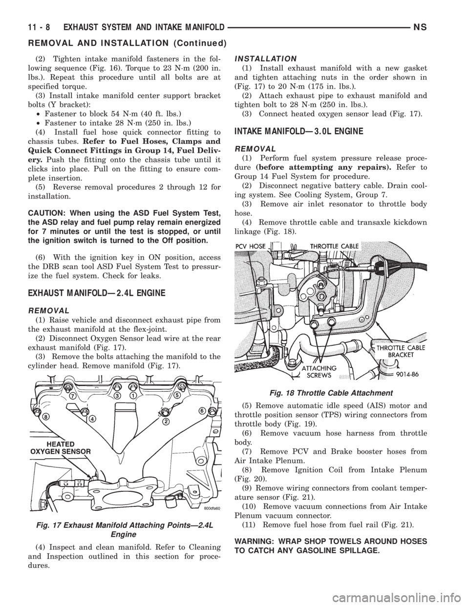
(2) Disconnect Oxygen Sensor lead wire at the rear
exhaust manifold (Fig. 17).
(3) Remove the bolts attaching the manifold to the
cylinder head. Remove manifold (Fig. 17).
(4) Inspect and clean manifold. Refer to Cleaning
and Inspection outlined in this section for proce-
dures.
INSTALLATION
(1) Install exhaust manifold with a new gasket
and tighten attaching nuts in the order shown in
(Fig. 17) to 20 N´m (175 in. lbs.).
(2) Attach exhaust pipe to exhaust manifold and
tighten bolt to 28 N´m (250 in. lbs.).
(3) Connect heated oxygen sensor lead (Fig. 17).
INTAKE MANIFOLDÐ3.0L ENGINE
REMOVAL
(1) Perform fuel system pressure release proce-
dure(before attempting any repairs).Refer to
Group 14 Fuel System for procedure.
(2) Disconnect negative battery cable. Drain cool-
ing system. See Cooling System, Group 7.
(3) Remove air inlet resonator to throttle body
hose.
(4) Remove throttle cable and transaxle kickdown
linkage (Fig. 18).
(5) Remove automatic idle speed (AIS) motor and
throttle position sensor (TPS) wiring connectors from
throttle body (Fig. 19).
(6) Remove vacuum hose harness from throttle
body.
(7) Remove PCV and Brake booster hoses from
Air Intake Plenum.
(8) Remove Ignition Coil from Intake Plenum
(Fig. 20).
(9) Remove wiring connectors from coolant temper-
ature sensor (Fig. 21).
(10) Remove vacuum connections from Air Intake
Plenum vacuum connector.
(11) Remove fuel hose from fuel rail (Fig. 21).
WARNING: WRAP SHOP TOWELS AROUND HOSES
TO CATCH ANY GASOLINE SPILLAGE.
Fig. 17 Exhaust Manifold Attaching PointsÐ2.4L
Engine
Fig. 18 Throttle Cable Attachment
11 - 8 EXHAUST SYSTEM AND INTAKE MANIFOLDNS
REMOVAL AND INSTALLATION (Continued)
Page 1305 of 1938

SERVICE PROCEDURES
FUEL SYSTEM PRESSURE RELEASE
PROCEDUREÐ2.4/3.3/3.8L
WARNING: RELEASE FUEL SYSTEM PRESSURE
BEFORE SERVICING FUEL SYSTEM COMPONENTS.
SERVICE VEHICLES IN WELL VENTILATED AREAS
AND AVOID IGNITION SOURCES. NEVER SMOKE
WHILE SERVICING THE VEHICLE.
(1) Disconnect negative cable from battery.
(2) Remove fuel filler cap.
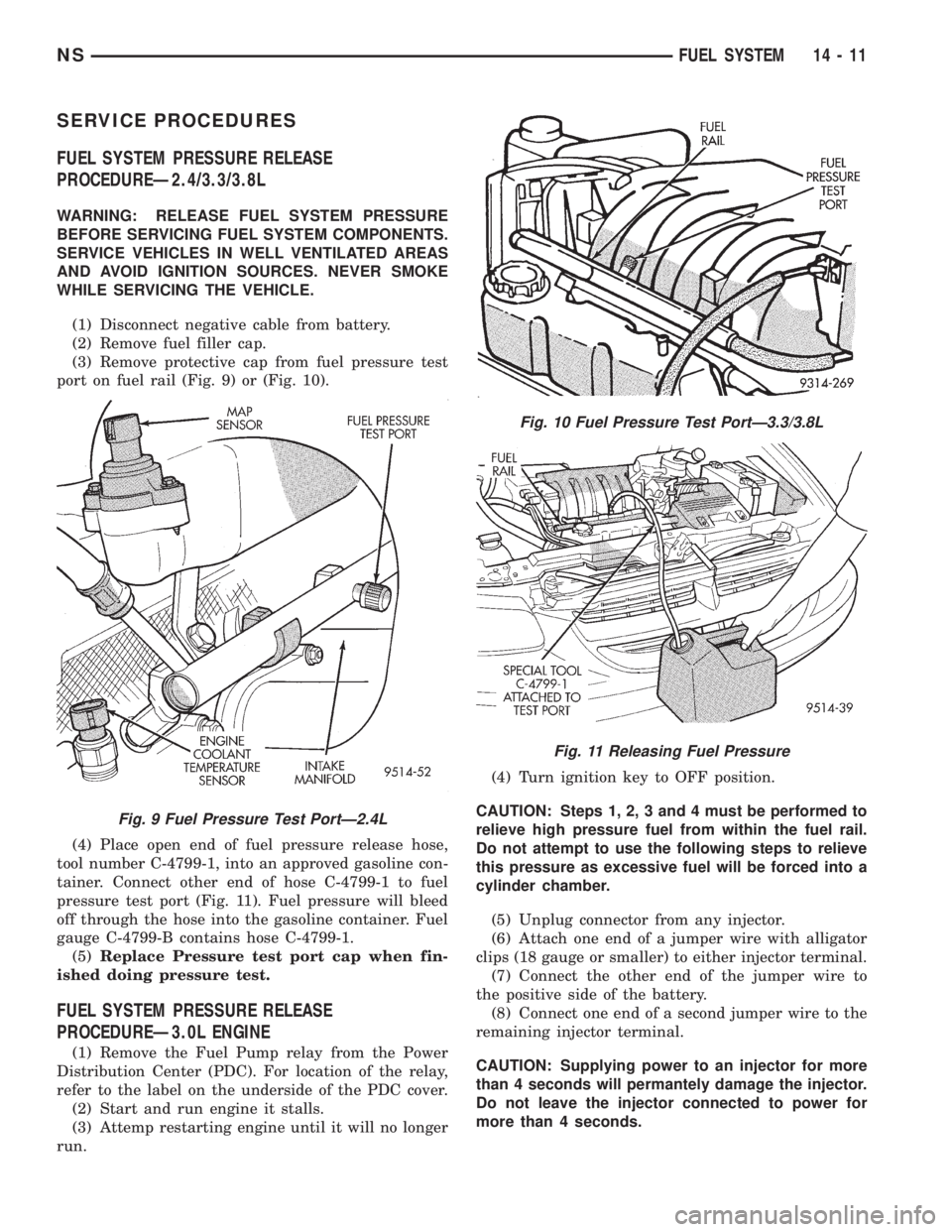
(3) Remove protective cap from fuel pressure test
port on fuel rail (Fig. 9) or (Fig. 10).
(4) Place open end of fuel pressure release hose,
tool number C-4799-1, into an approved gasoline con-
tainer. Connect other end of hose C-4799-1 to fuel
pressure test port (Fig. 11). Fuel pressure will bleed
off through the hose into the gasoline container. Fuel
gauge C-4799-B contains hose C-4799-1.
(5)Replace Pressure test port cap when fin-
ished doing pressure test.
FUEL SYSTEM PRESSURE RELEASE
PROCEDUREÐ3.0L ENGINE
(1) Remove the Fuel Pump relay from the Power
Distribution Center (PDC). For location of the relay,
refer to the label on the underside of the PDC cover.
(2) Start and run engine it stalls.
(3) Attemp restarting engine until it will no longer
run.(4) Turn ignition key to OFF position.
CAUTION: Steps 1, 2, 3 and 4 must be performed to
relieve high pressure fuel from within the fuel rail.
Do not attempt to use the following steps to relieve
this pressure as excessive fuel will be forced into a
cylinder chamber.
(5) Unplug connector from any injector.
(6) Attach one end of a jumper wire with alligator
clips (18 gauge or smaller) to either injector terminal.
(7) Connect the other end of the jumper wire to
the positive side of the battery.
(8) Connect one end of a second jumper wire to the
remaining injector terminal.
CAUTION: Supplying power to an injector for more
than 4 seconds will permantely damage the injector.
Do not leave the injector connected to power for
more than 4 seconds.
Fig. 9 Fuel Pressure Test PortÐ2.4L
Fig. 10 Fuel Pressure Test PortÐ3.3/3.8L
Fig. 11 Releasing Fuel Pressure
NSFUEL SYSTEM 14 - 11
Page 1313 of 1938

WARNING: WRAP A SHOP TOWEL AROUND
HOSES TO CATCH ANY GASOLINE SPILLAGE.
(12) Remove bolt holding bottom of intake support
bracket.
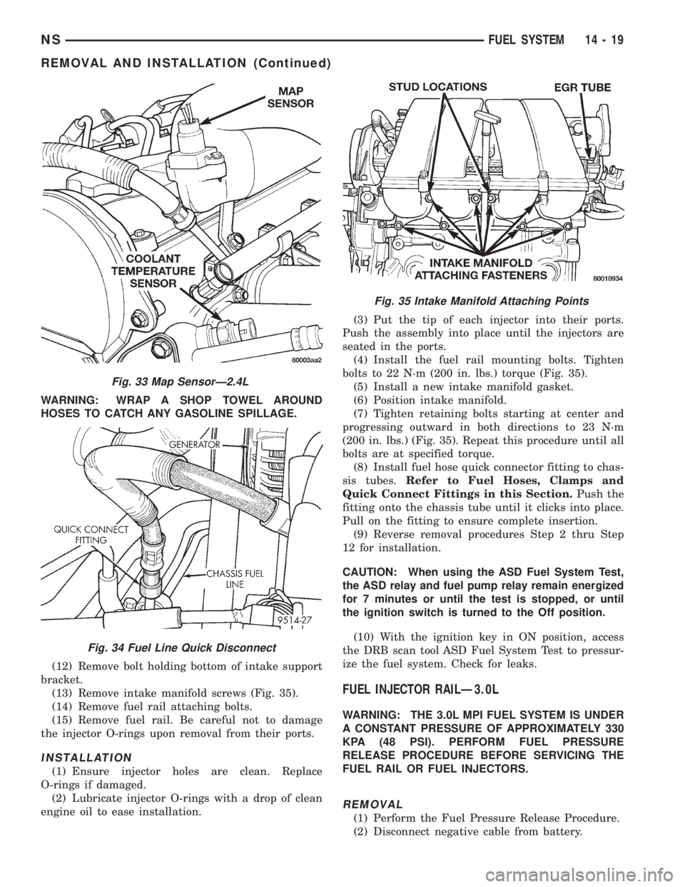
(13) Remove intake manifold screws (Fig. 35).
(14) Remove fuel rail attaching bolts.
(15) Remove fuel rail. Be careful not to damage
the injector O-rings upon removal from their ports.
INSTALLATION
(1) Ensure injector holes are clean. Replace
O-rings if damaged.
(2) Lubricate injector O-rings with a drop of clean
engine oil to ease installation.(3) Put the tip of each injector into their ports.
Push the assembly into place until the injectors are
seated in the ports.
(4) Install the fuel rail mounting bolts. Tighten
bolts to 22 N´m (200 in. lbs.) torque (Fig. 35).
(5) Install a new intake manifold gasket.
(6) Position intake manifold.
(7) Tighten retaining bolts starting at center and
progressing outward in both directions to 23 N´m
(200 in. lbs.) (Fig. 35). Repeat this procedure until all
bolts are at specified torque.
(8) Install fuel hose quick connector fitting to chas-
sis tubes.Refer to Fuel Hoses, Clamps and
Quick Connect Fittings in this Section.Push the
fitting onto the chassis tube until it clicks into place.
Pull on the fitting to ensure complete insertion.
(9) Reverse removal procedures Step 2 thru Step
12 for installation.
CAUTION: When using the ASD Fuel System Test,
the ASD relay and fuel pump relay remain energized
for 7 minutes or until the test is stopped, or until
the ignition switch is turned to the Off position.
(10) With the ignition key in ON position, access
the DRB scan tool ASD Fuel System Test to pressur-
ize the fuel system. Check for leaks.
FUEL INJECTOR RAILÐ3.0L
WARNING: THE 3.0L MPI FUEL SYSTEM IS UNDER
A CONSTANT PRESSURE OF APPROXIMATELY 330
KPA (48 PSI). PERFORM FUEL PRESSURE
RELEASE PROCEDURE BEFORE SERVICING THE
FUEL RAIL OR FUEL INJECTORS.
REMOVAL
(1) Perform the Fuel Pressure Release Procedure.
(2) Disconnect negative cable from battery.
Fig. 33 Map SensorÐ2.4L
Fig. 34 Fuel Line Quick Disconnect
Fig. 35 Intake Manifold Attaching Points
NSFUEL SYSTEM 14 - 19
REMOVAL AND INSTALLATION (Continued)
Page 1315 of 1938

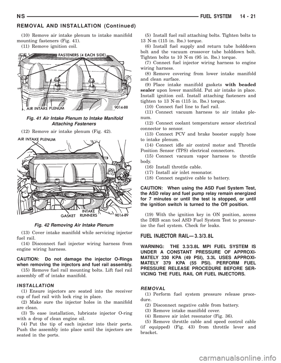
(10) Remove air intake plenum to intake manifold
mounting fasteners (Fig. 41).
(11) Remove ignition coil.
(12) Remove air intake plenum (Fig. 42).
(13) Cover intake manifold while servicing injector
fuel rail.
(14) Disconnect fuel injector wiring harness from
engine wiring harness.
CAUTION: Do not damage the injector O-Rings
when removing the injectors and fuel rail assembly.
(15) Remove fuel rail mounting bolts. Lift fuel rail
assembly off of intake manifold.
INSTALLATION
(1) Ensure injectors are seated into the receiver
cup of fuel rail with lock ring in place.
(2) Make sure the injector holes in the manifold
are clean.
(3) To ease installation, lubricate injector O-ring
with a drop of clean engine oil.
(4) Put the tip of each injector into their ports.
Push the assembly into place until the injectors are
seated in the ports.(5) Install fuel rail attaching bolts. Tighten bolts to
13 N´m (115 in. lbs.) torque.
(6) Install fuel supply and return tube holddown
bolt and the vacuum crossover tube holddown bolt.
Tighten bolts to 10 N´m (95 in. lbs.) torque.
(7) Connect fuel injector wiring harness to engine
wiring harness.
(8) Remove covering from lower intake manifold
and clean surface.
(9) Place intake manifold gasketswith beaded
sealerupon lower manifold. Put air intake in place.
Install ignition coil. Install attaching fasteners and
tighten to 13 N´m (115 in. lbs.) torque.
(10) Connect fuel line to fuel rail.
(11) Connect vacuum harness to air intake ple-
num.
(12) Connect coolant temperature sensor electrical
connector to sensor.
(13) Connect PCV and brake booster supply hose
to intake plenum.
(14) Connect idle air control motor and Throttle
Position Sensor (TPS) electrical connectors.
(15) Connect vacuum vapor harness to throttle
body.
(16) Install throttle cable.
(17) Install air inlet resonator.
(18) Connect negative cable to battery.
CAUTION: When using the ASD Fuel System Test,
the ASD relay and fuel pump relay remain energized
for 7 minutes or until the test is stopped, or until
the ignition switch is turned to the Off position.
(19) With the ignition key in ON position, access
the DRB scan tool ASD Fuel System Test to pressur-
ize the fuel system. Check for leaks.
FUEL INJECTOR RAILÐ3.3/3.8L
WARNING: THE 3.3/3.8L MPI FUEL SYSTEM IS
UNDER A CONSTANT PRESSURE OF APPROXI-
MATELY 330 KPA (49 PSI), 3.3L USES APPROXI-
MATELY 379 KPA (55 PSI). PERFORM FUEL
PRESSURE RELEASE PROCEDURE BEFORE SER-
VICING THE FUEL RAIL OR FUEL INJECTORS.
REMOVAL
(1) Perform fuel system pressure release proce-
dure.
(2) Disconnect negative cable from battery.
(3) Remove intake manifold cover.
(4) Remove air inlet resonator (Fig. 36).
(5) Remove throttle cable and speed control cable
(if equipped) (Fig. 43) from throttle lever and
bracket.
Fig. 41 Air Intake Plenum to Intake Manifold
Attaching Fasteners
Fig. 42 Removing Air Intake Plenum
NSFUEL SYSTEM 14 - 21
REMOVAL AND INSTALLATION (Continued)