1996 CHRYSLER VOYAGER key battery
[x] Cancel search: key batteryPage 1416 of 1938

The speed sensor generates 8 pulses per sensor
revolution. These signals, in conjunction with a
closed throttle signal from the throttle position sen-
sor, indicate a closed throttle deceleration to the
PCM. When the vehicle is stopped at idle, a closed
throttle signal is received by the PCM (but a speed
sensor signal is not received).
In addition to determining distance and vehicle
speed, the output from the sensor is used to control
speed control operation.
SPEED CONTROLÐPCM INPUTS
The speed control system provides five separate
inputs to the PCM; On/Off, Set, Resume/Accel, Cancel,
and Decel.. The On/Off input informs the PCM that
the speed control system has been activated. The Set
input informs the PCM that a fixed vehicle speed has
been selected. The Resume input indicates to the PCM
that the previous fixed speed is requested.
Speed control operation will start at 50 km/h±142
km/h (35±85 mph). The upper range of operation is
not restricted by vehicle speed. Inputs that affect
speed control operation are vehicle speed sensor and
throttle position sensor.
Refer to Group 8H for further speed control infor-
mation.
DIESEL PCM RELAYÐPCM INPUT
A 12 volt signal at this input indicates to the PCM
that the Diesel relay has been activated. The Diesel
relay is located in the PDC. The PDC is located next
to the battery in the engine compartment. For the
location of the relay within the PDC, refer to label on
PDC cover.
This input is used only to sense that the Diesel
relay is energized. If the PCM does not see 12 volts +
at this input when the Diesel relay should be acti-
vated, it will set a Diagnostic Trouble Code (DTC).
FIVE VOLT POWERÐPCM OUTPUT
This circuit supplies approximately 5 volts to
power the Accelerator Pedal Postion Sensor, Mass Air
Flow Sensor, and A/C Pressure Sensor.
ENGINE COOLANT GAUGEÐPCM OUTPUT
Refer to the Instrument Panel and Gauges group
for additional information.
ENGINE OIL PRESSURE GAUGEÐPCM OUTPUT
Refer to the Instrument Panel and Gauges group
for additional information.
GLOW PLUG LAMPÐPCM OUTPUT
The Glow Plug lamp (malfunction indicator lamp)
illuminates on the message center each time the igni-
tion (key) switch is turned on. It will stay on for
about two seconds as a bulb test.If the PCM receives an incorrect signal, or no sig-
nal from certain sensors or components, the lamp
BLINKS. This is a warning that the PCM has
recorded a system or sensor malfunction. It signals
an immediate need for service. There are only 5
HARD faults that can turn on this lamp to make it
blink.
SPEED CONTROLÐPCM OUTPUTS
These two circuits control the fuel quantity actua-
tor to regulate vehicle speed. Refer to Group 8H for
Speed Control information.
AIR CONDITIONING RELAYÐPCM OUTPUT
This circuit controls a ground signal for operation
of the A/C clutch relay. Also refer to Air Conditioning
(A/C) ControlsÐPCM Input for additional informa-
tion.
The A/C relay is located in the Power Distribution
Center (PDC). The PDC is located next to the battery
in the engine compartment. For the location of the
relay within the PDC, refer to label on PDC cover.
FUEL TIMING SOLENOIDÐPCM OUTPUT
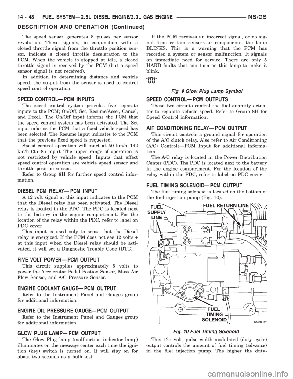
The fuel timing solenoid is located on the bottom of
the fuel injection pump (Fig. 10).
This 12+ volt, pulse width modulated (duty±cycle)
output controls the amount of fuel timing (advance)
in the fuel injection pump. The higher the duty-
Fig. 9 Glow Plug Lamp Symbol
Fig. 10 Fuel Timing Solenoid
14 - 48 FUEL SYSTEMÐ2.5L DIESEL ENGINE/2.0L GAS ENGINENS/GS
DESCRIPTION AND OPERATION (Continued)
Page 1419 of 1938

to Group 8W for wiring connector and circuitry infor-
mation. Repair the wire harness if an open circuit is
indicated.
(4) After tests are completed, connect electrical
connector to sensor.
GLOW PLUG TEST
Hard starting or a rough idle after starting may be
caused by one or more defective glow plugs. Before
testing the glow plugs, a test of the glow plug relay
should be performed. This will ensure that 12V+ is
available at the plugs when starting the engine.
Refer to the Glow Plug Relay Test for information.
For accurate test results, the glow plugs should be
removed from the engine. The plugs must be checked
when cold.Do not check the plugs if the engine
has recently been operated. If plugs are
checked when warm, incorrect amp gauge
readings will result.
Use Churchill Glow Plug Tester DX.900 or an
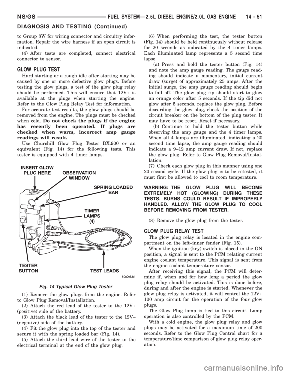
equivalent (Fig. 14) for the following tests. This
tester is equipped with 4 timer lamps.
(1) Remove the glow plugs from the engine. Refer
to Glow Plug Removal/Installation.
(2) Attach the red lead of the tester to the 12V+
(positive) side of the battery.
(3) Attach the black lead of the tester to the 12V±
(negative) side of the battery.
(4) Fit the glow plug into the top of the tester and
secure it with the spring loaded bar (Fig. 14).
(5) Attach the third lead wire of the tester to the
electrical terminal at the end of the glow plug.(6) When performing the test, the tester button
(Fig. 14) should be held continuously without release
for 20 seconds as indicated by the 4 timer lamps.
Each illuminated lamp represents a 5 second time
lapse.
(a) Press and hold the tester button (Fig. 14)
and note the amp gauge reading. The gauge read-
ing should indicate a momentary, initial current
draw (surge) of approximately 25 amps. After the
initial surge, the amp gauge reading should begin
to fall off. The glow plug tip should start to glow
an orange color after 5 seconds. If the tip did not
glow after 5 seconds, replace the glow plug. Before
discarding the glow plug, check the position of the
circuit breaker on the bottom of the plug tester. It
may have to be reset. Reset if necessary.
(b) Continue to hold the tester button while
observing the amp gauge and the 4 timer lamps.
When all 4 lamps are illuminated, indicating a 20
second time lapse, the amp gauge reading should
indicate a 9±12 amp current draw. If not, replace
the glow plug. Refer to Glow Plug Removal/Instal-
lation.
(7) Check each glow plug in this manner using one
20 second cycle. If the glow plug is to be retested, it
must first be allowed to cool to room temperature.
WARNING: THE GLOW PLUG WILL BECOME
EXTREMELY HOT (GLOWING) DURING THESE
TESTS. BURNS COULD RESULT IF IMPROPERLY
HANDLED. ALLOW THE GLOW PLUG TO COOL
BEFORE REMOVING FROM TESTER.
(8) Remove the glow plug from the tester.
GLOW PLUG RELAY TEST
The glow plug relay is located in the engine com-
partment on the left±inner fender (Fig. 15).
When the ignition (key) switch is placed in the ON
position, a signal is sent to the PCM relating current
engine coolant temperature. This signal is sent from
the engine coolant temperature sensor.
After receiving this signal, the PCM will deter-
mine if, when and for how long a period the glow
plug relay should be activated. This is done before,
during and after the engine is started. Whenever the
glow plug relay is activated, it will control the 12V+
100 amp circuit for the operation of the four glow
plugs.
The Glow Plug lamp is tied to this circuit. Lamp
operation is also controlled by the PCM.
With a cold engine, the glow plug relay and glow
plugs may be activated for a maximum time of 200
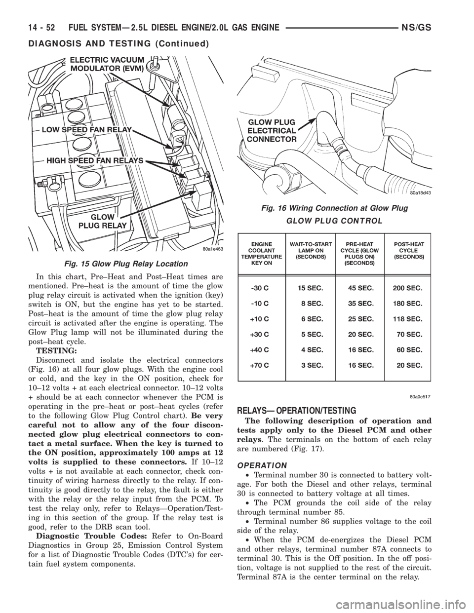
seconds. Refer to the Glow Plug Control chart for a
temperature/time comparison of glow plug relay oper-
ation.
Fig. 14 Typical Glow Plug Tester
NS/GSFUEL SYSTEMÐ2.5L DIESEL ENGINE/2.0L GAS ENGINE 14 - 51
DIAGNOSIS AND TESTING (Continued)
Page 1420 of 1938

In this chart, Pre±Heat and Post±Heat times are
mentioned. Pre±heat is the amount of time the glow
plug relay circuit is activated when the ignition (key)
switch is ON, but the engine has yet to be started.
Post±heat is the amount of time the glow plug relay
circuit is activated after the engine is operating. The
Glow Plug lamp will not be illuminated during the
post±heat cycle.
TESTING:
Disconnect and isolate the electrical connectors
(Fig. 16) at all four glow plugs. With the engine cool
or cold, and the key in the ON position, check for
10±12 volts + at each electrical connector. 10±12 volts
+ should be at each connector whenever the PCM is
operating in the pre±heat or post±heat cycles (refer
to the following Glow Plug Control chart).Be very
careful not to allow any of the four discon-
nected glow plug electrical connectors to con-
tact a metal surface. When the key is turned to
the ON position, approximately 100 amps at 12
volts is supplied to these connectors.If 10±12
volts + is not available at each connector, check con-
tinuity of wiring harness directly to the relay. If con-
tinuity is good directly to the relay, the fault is either
with the relay or the relay input from the PCM. To
test the relay only, refer to RelaysÐOperation/Test-
ing in this section of the group. If the relay test is
good, refer to the DRB scan tool.
Diagnostic Trouble Codes:Refer to On-Board
Diagnostics in Group 25, Emission Control System
for a list of Diagnostic Trouble Codes (DTC's) for cer-
tain fuel system components.
RELAYSÐOPERATION/TESTING
The following description of operation and
tests apply only to the Diesel PCM and other
relays. The terminals on the bottom of each relay
are numbered (Fig. 17).
OPERATION
²Terminal number 30 is connected to battery volt-
age. For both the Diesel and other relays, terminal
30 is connected to battery voltage at all times.
²The PCM grounds the coil side of the relay
through terminal number 85.
²Terminal number 86 supplies voltage to the coil
side of the relay.
²When the PCM de-energizes the Diesel PCM
and other relays, terminal number 87A connects to
terminal 30. This is the Off position. In the off posi-
tion, voltage is not supplied to the rest of the circuit.
Terminal 87A is the center terminal on the relay.
Fig. 15 Glow Plug Relay Location
Fig. 16 Wiring Connection at Glow Plug
GLOW PLUG CONTROL
14 - 52 FUEL SYSTEMÐ2.5L DIESEL ENGINE/2.0L GAS ENGINENS/GS
DIAGNOSIS AND TESTING (Continued)
Page 1464 of 1938

DIAGNOSIS AND TESTING
STEERING COLUMN
For diagnosis of conditions relating to the steering
column, refer to the steering system diagnosis charts,
in the diagnosis and testing section at the beginning
of this group.
SERVICE PROCEDURES
STEERING COLUMN SERVICE PROCEDURE
WARNINGS
WARNING: BEFORE BEGINNING ANY SERVICE
PROCEDURES THAT INVOLVES REMOVING THE
AIR BAG. REMOVE AND ISOLATE THE NEGATIVE
(-) BATTERY CABLE (GROUND) FROM THE VEHI-
CLE BATTERY. THIS IS THE ONLY SURE WAY TO
DISABLE THE AIR BAG SYSTEM. FAILURE TO DO
THIS COULD RESULT IN ACCIDENTAL AIR BAG
DEPLOYMENT AND POSSIBLE PERSONAL INJURY.
WARNING: THE AIR BAG SYSTEM IS A SENSITIVE,
COMPLEX ELECTRO-MECHANICAL UNIT. BEFORE
ATTEMPTING TO DIAGNOSE, REMOVE OR INSTALL
THE AIR BAG SYSTEM COMPONENTS YOU MUST
FIRST DISCONNECT AND ISOLATE THE BATTERY
NEGATIVE (GROUND) CABLE. FAILURE TO DO SO
COULD RESULT IN ACCIDENTAL DEPLOYMENT OF
THE AIR BAG AND POSSIBLE PERSONAL INJURY.
THE FASTENERS, SCREWS, AND BOLTS, ORIGI-
NALLY USED FOR THE AIR BAG COMPONENTS,
HAVE SPECIAL COATINGS AND ARE SPECIFI-
CALLY DESIGNED FOR THE AIR BAG SYSTEM.
THEY MUST NEVER BE REPLACED WITH ANY SUB-
STITUTES. ANYTIME A NEW FASTENER IS
NEEDED, REPLACE WITH THE CORRECT FASTEN-
ERS PROVIDED IN THE SERVICE PACKAGE OR
FASTENERS LISTED IN THE PARTS BOOKS.
BEFORE SERVICING A STEERING COLUMN
EQUIPPED WITH AN AIR BAG, REFER TO GROUP
8M, ELECTRICAL FOR PROPER AND SAFE SER-
VICE PROCEDURES.
NOTE: Safety goggles should be worn at all times
when working on steering columns.
CAUTION: Disconnect negative (ground) cable
from the battery, before servicing any column com-
ponent.CAUTION: Do not attempt to remove the pivot pins
to disassemble the tilting mechanism. Damage will
occur.
REMOVAL AND INSTALLATION
STEERING COLUMN ASSEMBLY
To service the steering wheel and its components
or the air bag, refer to Group 8M, Restraint Systems.
Follow all WARNINGS.
To service the switches, refer to the appropriate
section of Group 8, Electrical.
To replace the steering column assembly, refer to
the steering column removal procedure.
REMOVE
(1) Make sure the front wheels of the vehicle are
in thestraight aheadposition before beginning the
column removal procedure.
(2) Disconnect negative (ground) cable from the
battery and isolate cable from battery terminal.
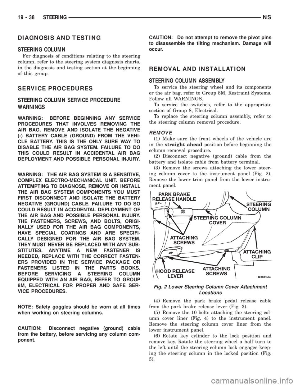
(3) Remove the screws attaching the lower steer-
ing column cover to the instrument panel (Fig. 2).
Remove the lower trim panel from the lower instru-
ment panel.
(4) Remove the park brake pedal release cable
from the park brake release lever (Fig. 3).
(5) Remove the 10 bolts attaching the steering col-
umn cover liner (Fig. 4) to the instrument panel.
Remove the steering column cover liner from the
lower instrument panel.
(6) Rotate key cylinder to the lock position and
remove key. Rotate the steering wheel a half turn to
the left until the steering column lock engages keep-
ing the steering column in the locked position (Fig.
5).
Fig. 2 Lower Steering Column Cover Attachment
Locations
19 - 38 STEERINGNS