1996 CHRYSLER VOYAGER oil filter
[x] Cancel search: oil filterPage 1169 of 1938
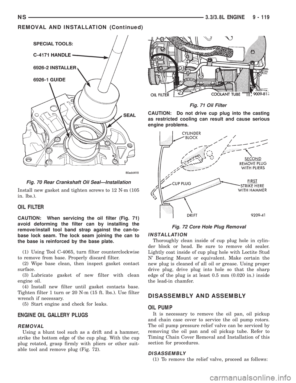
Install new gasket and tighten screws to 12 N´m (105
in. lbs.).
OIL FILTER
CAUTION: When servicing the oil filter (Fig. 71)
avoid deforming the filter can by installing the
remove/install tool band strap against the can-to-
base lock seam. The lock seam joining the can to
the base is reinforced by the base plate.
(1) Using Tool C-4065, turn filter counterclockwise
to remove from base. Properly discard filter.
(2) Wipe base clean, then inspect gasket contact
surface.
(3) Lubricate gasket of new filter with clean
engine oil.
(4) Install new filter until gasket contacts base.
Tighten filter 1 turn or 20 N´m (15 ft. lbs.). Use filter
wrench if necessary.
(5) Start engine and check for leaks.
ENGINE OIL GALLERY PLUGS
REMOVAL
Using a blunt tool such as a drift and a hammer,
strike the bottom edge of the cup plug. With the cup
plug rotated, grasp firmly with pliers or other suit-
able tool and remove plug (Fig. 72).CAUTION: Do not drive cup plug into the casting
as restricted cooling can result and cause serious
engine problems.
INSTALLATION
Thoroughly clean inside of cup plug hole in cylin-
der block or head. Be sure to remove old sealer.
Lightly coat inside of cup plug hole with Loctite Stud
N' Bearing Mount or equivalent. Make certain the
new plug is cleaned of all oil or grease. Using proper
drive plug, drive plug into hole so that the sharp
edge of the plug is at least 0.5 mm (0.020 in.) inside
the lead-in chamfer.
DISASSEMBLY AND ASSEMBLY
OIL PUMP
It is necessary to remove the oil pan, oil pickup
and chain case cover to service the oil pump rotors.
The oil pump pressure relief valve can be serviced by
removing the oil pan and oil pickup tube. Refer to
Timing Chain Cover Removal and Installation of this
section for procedures.
DISASSEMBLY
(1) To remove the relief valve, proceed as follows:
Fig. 70 Rear Crankshaft Oil SealÐInstallation
Fig. 71 Oil Filter
Fig. 72 Core Hole Plug Removal
NS3.3/3.8L ENGINE 9 - 119
REMOVAL AND INSTALLATION (Continued)
Page 1175 of 1938
Service Tappets Available........Std., 0.025 mm
(0.001), 0.20 mm (0.008 in.),
0.762 mm (0.030 in.)
Cylinder Head
Gasket Thickness (Compressed)........1.78 mm
(0.070 in.)
Cylinder Head Valve Seat
Angle±Intake and Exhaust...........45-45.5É
Runout (Max)............0.0762 mm (0.003 in.)
Width (Finish)±Intake...........1.75 - 2.25 mm
(0.069 - 0.088 in.)
Width (Finish)±Exhaust.........1.50 - 2.00 mm
(0.057 - 0.078 in.)
Valve Guides
Type..................Powdered Metal Inserts
Guide Bore Diameter...........7.975 - 8.00 mm
(0.314 - 0.315 in.)
ValvesÐIntake
Face Angle...........................44.5É
Head Diameter..............45.5 mm (1.79 in.)
Length (Overall)..........127.005 - 128.036 mm
(5.000 - 5.041 in.)
Minimum Valve Length
After Tip Grinding...................124.892
(4.916 in.)
Lift (Zero Lash)...........10.16 mm (0.400 in.)
Stem Diameter (Standard)......7.935 - 7.953 mm
(0.312 - 0.313 in.)
Valve Tip Height (From
Cylinder Head Surface)......49.541 - 51.271 mm
(1.950 - 2.018 in.)
Stem-to-Guide Clearance.......0.025 - 0.095 mm
(0.001 - 0.003 in.)
Max. Allowable (Rocking Method). . . .0.247 mm
(0.010 in.)
Valves for Service
(Oversize Stem Diameters).......Std., 0.015 mm
(0.005 in.), 0.40 mm (0.015 in.),
0.80 mm (0.030 in.)
ValvesÐExhaust
Face Angle.............................45É
Head Diameter.............37.5 mm (1.476 in.)
Length Overall..............127.825 - 128.465
(5.032 - 5.058 in.)
Minimum Valve Length
After Tip Grinding.......125.512 mm (4.941 in.)
Lift (Zero Lash)............10.16 mm (0.40 in.)
Valve Tip Height (From
Cylinder Head Surface)......49.541 - 51.271 mm
(1.950 - 2.018 in.)
Stem Diameter (Standar).......7.906 - 7.924 mm
(0.3112 - 0.3119 in.)
Stem to Guide Clearance.......0.051 - 0.175 mm
(0.002 - 0.006 in.)Max. Allowable (Rocking Method)......0.414 mm
(0.016 in.)
Valves for Service (Oversize
Stem Diameters)......Std., 0.015 mm (0.005 in.),
0.40 mm (0.015 in.), 0.80 mm (0.030 in.)
Valve Springs
Free Length (Approx.).......48.5 mm (1.909 in.)
Wire Diameter.............4.75 mm (0.187 in.)
Number of Coils.........................6.8
Spring Tension (Valve Closed).......95-100lbs.
@ 1.57 in.
Spring Tension (Valve Open).......207 - 229 lbs.
@ 1.169 in.
Installed Height (Spring
Seat to Bottom of Retainer)......41.2 - 42.7 mm
(1.622 - 1.681 in.)
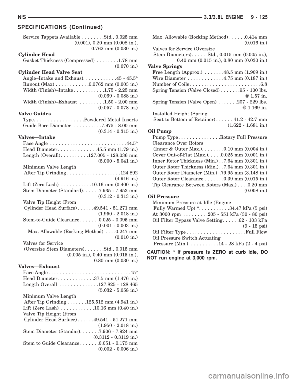
Oil Pump
Pump Type...............Rotary Full Pressure
Clearance Over Rotors
(Inner & Outer Max.)........0.10 mm (0.004 in.)
Cover Out-of-Flat (Max.).....0.025 mm (0.001 in.)
Inner Rotor Thickness (Min.) . .7.64 mm (0.301 in.)
Outer Rotor Thickness (Min.) . .7.64 mm (0.301 in.)
Outer Rotor Diameter (Min.) .79.95 mm (3.148 in.)
Outer Rotor Clearance.......0.39 mm (0.015 in.)
Tip Clearance Between Rotors (Max.). . . .0.20 mm
(0.008 in.)
Oil Pressure
Minimum Pressure at Idle (Engine
Fully Warmed Up)*...........34.47 kPa (5 psi)
At 3000 rpm.........205 - 551 kPa (30 - 80 psi)
Oil Filter Bypass Valve Setting......62-103kPa
(9 - 15 psi)
Oil Filter Type.....................Full Flow
Oil Pressure Switch Actuating
Pressure (Min.)...........14-28kPa(2 - 4 psi)
CAUTION: * If pressure is ZERO at curb Idle, DO
NOT run engine at 3,000 rpm.
NS3.3/3.8L ENGINE 9 - 125
SPECIFICATIONS (Continued)
Page 1176 of 1938
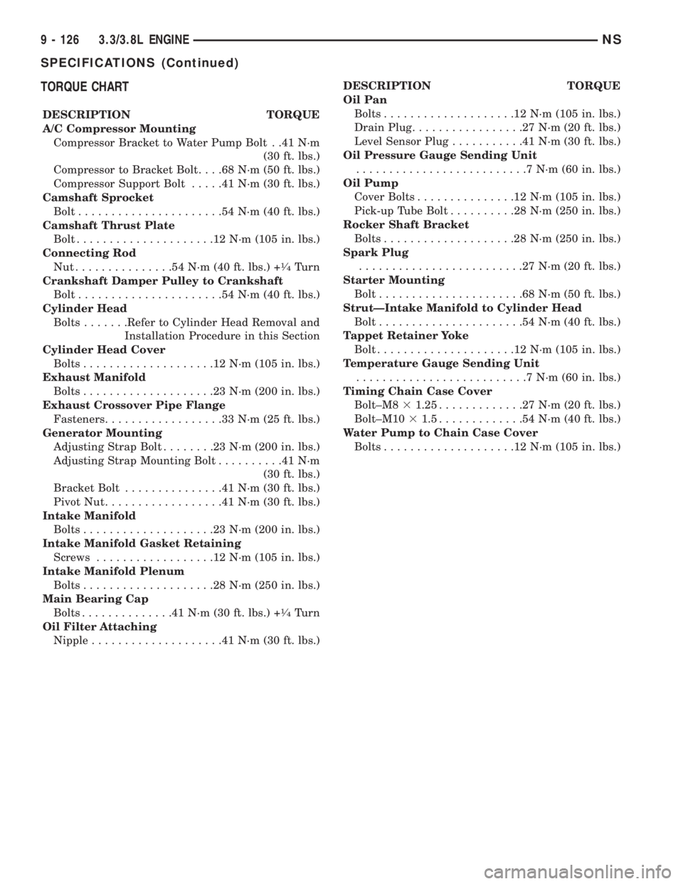
TORQUE CHART
DESCRIPTION TORQUE
A/C Compressor Mounting
Compressor Bracket to Water Pump Bolt . .41 N´m
(30 ft. lbs.)
Compressor to Bracket Bolt. . . .68 N´m (50 ft. lbs.)
Compressor Support Bolt.....41N´m(30ft.lbs.)
Camshaft Sprocket
Bolt......................54N´m(40ft.lbs.)
Camshaft Thrust Plate
Bolt.....................12N´m(105 in. lbs.)
Connecting Rod
Nut...............54N´m(40ft.lbs.) +
1¤4Turn
Crankshaft Damper Pulley to Crankshaft
Bolt......................54N´m(40ft.lbs.)
Cylinder Head
Bolts.......Refer to Cylinder Head Removal and
Installation Procedure in this Section
Cylinder Head Cover
Bolts....................12N´m(105 in. lbs.)
Exhaust Manifold
Bolts....................23N´m(200 in. lbs.)
Exhaust Crossover Pipe Flange
Fasteners..................33N´m(25ft.lbs.)
Generator Mounting
Adjusting Strap Bolt........23N´m(200 in. lbs.)
Adjusting Strap Mounting Bolt..........41N´m
(30 ft. lbs.)
Bracket Bolt...............41N´m(30ft.lbs.)
Pivot Nut..................41N´m(30ft.lbs.)
Intake Manifold
Bolts....................23N´m(200 in. lbs.)
Intake Manifold Gasket Retaining
Screws..................12N´m(105 in. lbs.)
Intake Manifold Plenum
Bolts....................28N´m(250 in. lbs.)
Main Bearing Cap
Bolts..............41N´m(30ft.lbs.) +
1¤4Turn
Oil Filter Attaching
Nipple....................41N´m(30ft.lbs.)DESCRIPTION TORQUE
Oil Pan
Bolts....................12N´m(105 in. lbs.)
Drain Plug.................27N´m(20ft.lbs.)
Level Sensor Plug...........41N´m(30ft.lbs.)
Oil Pressure Gauge Sending Unit
..........................7N´m(60in.lbs.)
Oil Pump
Cover Bolts...............12N´m(105 in. lbs.)
Pick-up Tube Bolt..........28N´m(250 in. lbs.)
Rocker Shaft Bracket
Bolts....................28N´m(250 in. lbs.)
Spark Plug
.........................27N´m(20ft.lbs.)
Starter Mounting
Bolt......................68N´m(50ft.lbs.)
StrutÐIntake Manifold to Cylinder Head
Bolt......................54N´m(40ft.lbs.)
Tappet Retainer Yoke
Bolt.....................12N´m(105 in. lbs.)
Temperature Gauge Sending Unit
..........................7N´m(60in.lbs.)
Timing Chain Case Cover
Bolt±M831.25.............27N´m(20ft.lbs.)
Bolt±M1031.5.............54N´m(40ft.lbs.)
Water Pump to Chain Case Cover
Bolts....................12N´m(105 in. lbs.)
9 - 126 3.3/3.8L ENGINENS
SPECIFICATIONS (Continued)
Page 1178 of 1938
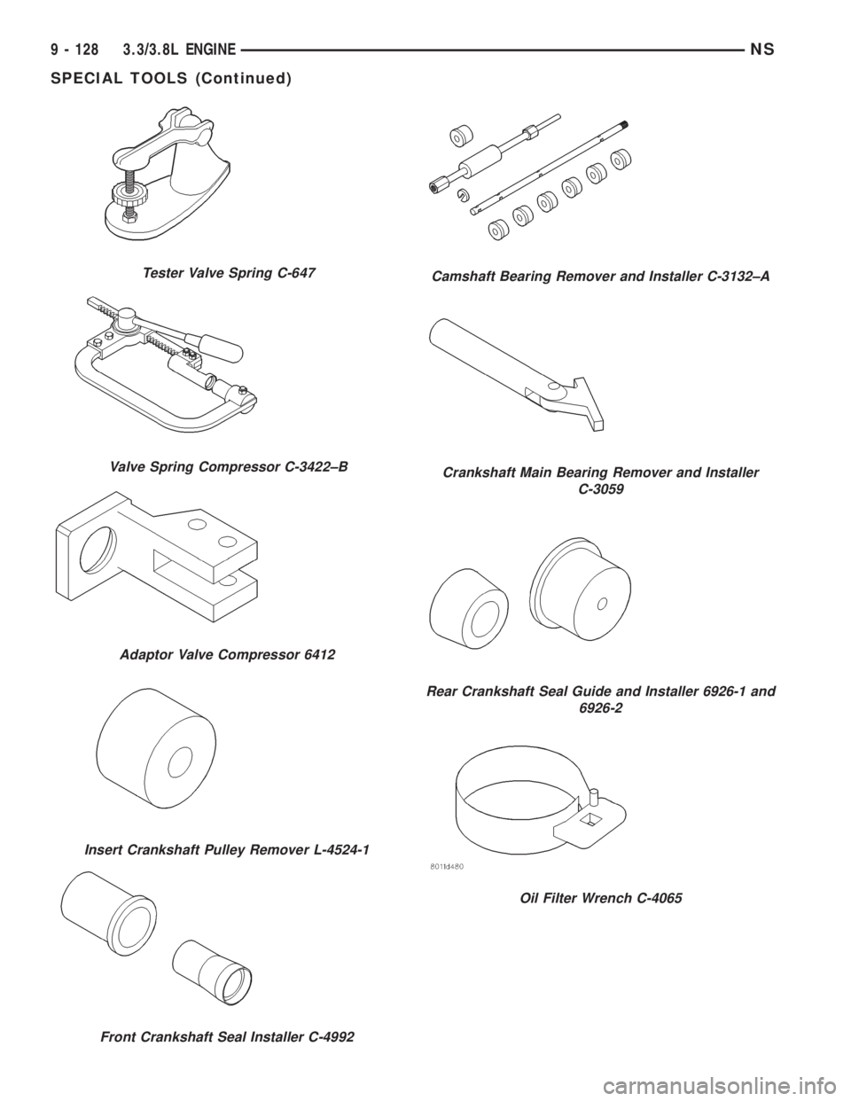
Tester Valve Spring C-647
Valve Spring Compressor C-3422±B
Adaptor Valve Compressor 6412
Insert Crankshaft Pulley Remover L-4524-1
Front Crankshaft Seal Installer C-4992
Camshaft Bearing Remover and Installer C-3132±A
Crankshaft Main Bearing Remover and Installer
C-3059
Rear Crankshaft Seal Guide and Installer 6926-1 and
6926-2
Oil Filter Wrench C-4065
9 - 128 3.3/3.8L ENGINENS
SPECIAL TOOLS (Continued)
Page 1179 of 1938
ENGINE
CONTENTS
page page
2.0L SOHC ENGINE...................... 12.5L VM DIESEL....................... 40
2.0L SOHC ENGINE
INDEX
page page
DESCRIPTION AND OPERATION
ENGINE COMPONENTS.................. 3
ENGINE IDENTIFICATION................. 1
ENGINE LUBRICATION SYSTEM............ 2
GENERAL SPECIFICATION................ 2
DIAGNOSIS AND TESTING
CHECKING ENGINE OIL PRESSURE........ 3
SERVICE PROCEDURES
CRANKSHAFT END PLAY................. 6
CYLINDER BORE AND PISTON SIZING....... 4
FITTING CONNECTING RODS.............. 5
FITTING CRANKSHAFT BEARINGS.......... 6
FITTING PISTON RINGS.................. 4
REMOVAL AND INSTALLATION
CAMSHAFT OIL SEAL................... 12
CAMSHAFT............................ 7
CRANKSHAFT OIL SEALÐREAR........... 20
CRANKSHAFT......................... 21
CYLINDER HEAD COVER................. 6
CYLINDER HEAD....................... 10
FRONT CRANKSHAFT OIL SEAL........... 18
OILFILTER ........................... 24
OIL FILTER ADAPTER................... 24OILPAN .............................. 17
OIL PUMP............................ 25
PISTON AND CONNECTING ROD.......... 25
ROCKER ARM/HYDRAULIC LASH ADJUSTER . . 8
SPARK PLUG TUBE...................... 7
TIMING BELT COVER................... 11
TIMING BELT SYSTEM.................. 13
VALVE SEALS AND SPRINGS IN VEHICLE . . . 10
VIBRATION DAMPER.................... 28
DISASSEMBLY AND ASSEMBLY
OIL PUMP............................ 29
VALVE SERVICE WITH THE CYLINDER HEAD
REMOVED.......................... 29
CLEANING AND INSPECTION
CYLINDER BLOCK AND BORE............ 34
CYLINDER HEAD AND CAMSHAFT
JOURNALS.......................... 32
OIL PUMP............................ 32
SPECIFICATIONS
ENGINE 2.0L SOHC..................... 34
TORQUE CHART 2.0L SOHC.............. 36
SPECIAL TOOLS
ENGINE 2.0L SOHC..................... 36
DESCRIPTION AND OPERATION
ENGINE IDENTIFICATION
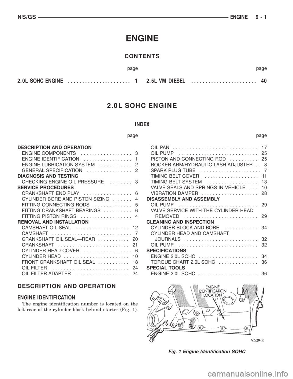
The engine identification number is located on the
left rear of the cylinder block behind starter (Fig. 1).
Fig. 1 Engine Identification SOHC
NS/GSENGINE 9 - 1
Page 1195 of 1938
²Turn the ignition switch on and access the ªmis-
cellaneousº screen.
²Select ªre-learn cam/crankº option and follow
directions on DRB screen.
OIL PAN
REMOVAL
(1) Drain engine oil.
(2) Remove transmission inspection cover.
(3) If equipped with air conditioning remove oil fil-
ter and adaptor. Refer to Oil Filter Adapter Removal
and Installation in this section.
(4) Remove oil pan.(5) Clean oil pan and all gasket surfaces.
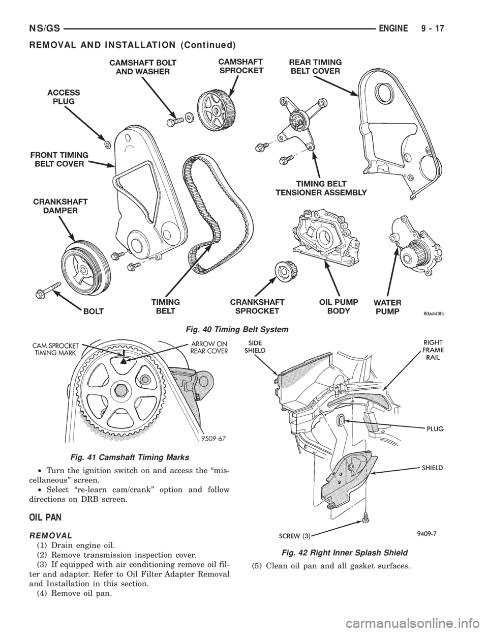
Fig. 40 Timing Belt System
Fig. 41 Camshaft Timing Marks
Fig. 42 Right Inner Splash Shield
NS/GSENGINE 9 - 17
REMOVAL AND INSTALLATION (Continued)
Page 1196 of 1938
INSTALLATION
(1) Apply Mopar Silicone Rubber Adhesive Sealant
or equivalent at the oil pump to engine block parting
line (Fig. 52).
(2) Install a new oil pan gasket to pan.
(3) Install pan and tighten screws to 12 N´m (105
in. lbs.).
(4) Install oil filter and adaptor.
(5) Install proper amount of oil. With oil filter 4.25
Liters (4.5 Qts.). Without oil filter 3.8 Liters (4.0
Qts.)
FRONT CRANKSHAFT OIL SEAL
REMOVAL
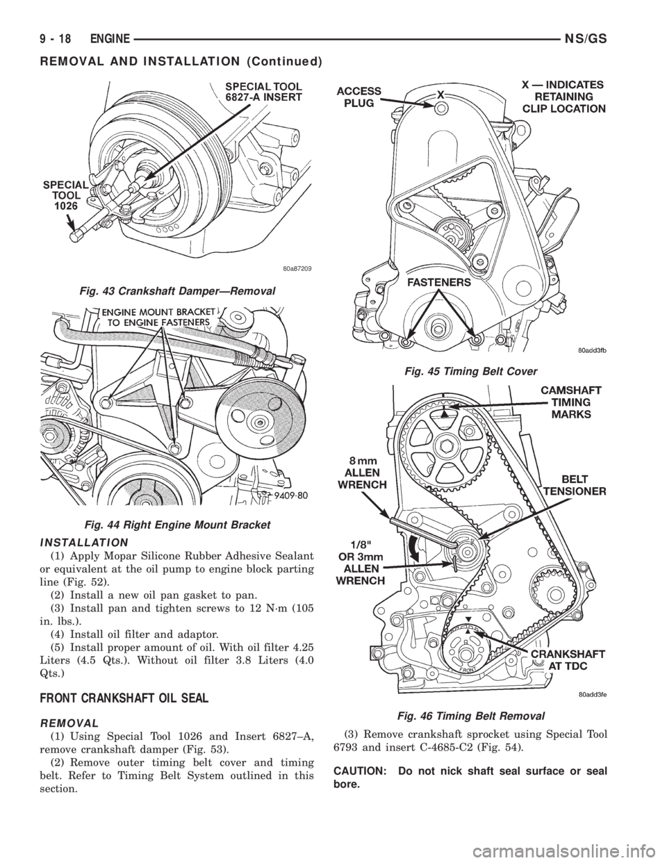
(1) Using Special Tool 1026 and Insert 6827±A,
remove crankshaft damper (Fig. 53).
(2) Remove outer timing belt cover and timing
belt. Refer to Timing Belt System outlined in this
section.(3) Remove crankshaft sprocket using Special Tool
6793 and insert C-4685-C2 (Fig. 54).
CAUTION: Do not nick shaft seal surface or seal
bore.
Fig. 43 Crankshaft DamperÐRemoval
Fig. 44 Right Engine Mount Bracket
Fig. 45 Timing Belt Cover
Fig. 46 Timing Belt Removal
9 - 18 ENGINENS/GS
REMOVAL AND INSTALLATION (Continued)
Page 1199 of 1938
NOTE: When installing seal, no lube on seal is
needed.
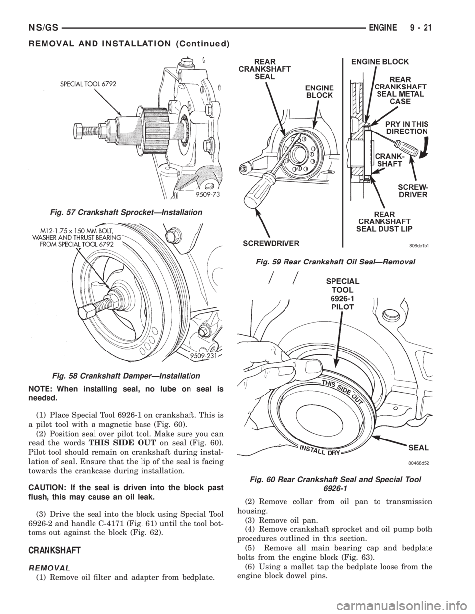
(1) Place Special Tool 6926-1 on crankshaft. This is
a pilot tool with a magnetic base (Fig. 60).
(2) Position seal over pilot tool. Make sure you can
read the wordsTHIS SIDE OUTon seal (Fig. 60).
Pilot tool should remain on crankshaft during instal-
lation of seal. Ensure that the lip of the seal is facing
towards the crankcase during installation.
CAUTION: If the seal is driven into the block past
flush, this may cause an oil leak.
(3) Drive the seal into the block using Special Tool
6926-2 and handle C-4171 (Fig. 61) until the tool bot-
toms out against the block (Fig. 62).
CRANKSHAFT
REMOVAL
(1) Remove oil filter and adapter from bedplate.(2) Remove collar from oil pan to transmission
housing.
(3) Remove oil pan.
(4) Remove crankshaft sprocket and oil pump both
procedures outlined in this section.
(5) Remove all main bearing cap and bedplate
bolts from the engine block (Fig. 63).
(6) Using a mallet tap the bedplate loose from the
engine block dowel pins.
Fig. 57 Crankshaft SprocketÐInstallation
Fig. 58 Crankshaft DamperÐInstallation
Fig. 59 Rear Crankshaft Oil SealÐRemoval
Fig. 60 Rear Crankshaft Seal and Special Tool
6926-1
NS/GSENGINE 9 - 21
REMOVAL AND INSTALLATION (Continued)