1996 CHRYSLER VOYAGER oil filter
[x] Cancel search: oil filterPage 1226 of 1938
ENGINE OIL CHANGE
WARNING: NEW OR USED ENGINE OIL CAN BE
IRRITATING TO THE SKIN. AVOID PROLONGED OR
REPEATED SKIN CONTACT WITH ENGINE OIL.
CONTAMINANTS IN USED ENGINE OIL, CAUSED BY
INTERNAL COMBUSTION, CAN BE HAZARDOUS TO
YOUR HEALTH. THOROUGHLY WASH EXPOSED
SKIN WITH SOAP AND WATER. DO NOT WASH
SKIN WITH GASOLINE, DIESEL FUEL, THINNER, OR
SOLVENTS, HEALTH PROBLEMS CAN RESULT. DO
NOT POLLUTE, DISPOSE OF USED ENGINE OIL
PROPERLY. CONTACT YOUR DEALER OR GOVERN-
MENT AGENCY FOR LOCATION OF COLLECTION
CENTER IN YOUR AREA.
Run engine until achieving normal operating tem-
perature.
(1) Position the vehicle on a level surface and turn
engine off.
(2) Remove oil fill cap.
(3) Hoist vehicle. Refer to Hoisting and Jacking
Recommendations.
(4) Place a suitable drain pan under crankcase
drain.
(5) Remove drain plug from crankcase and allow
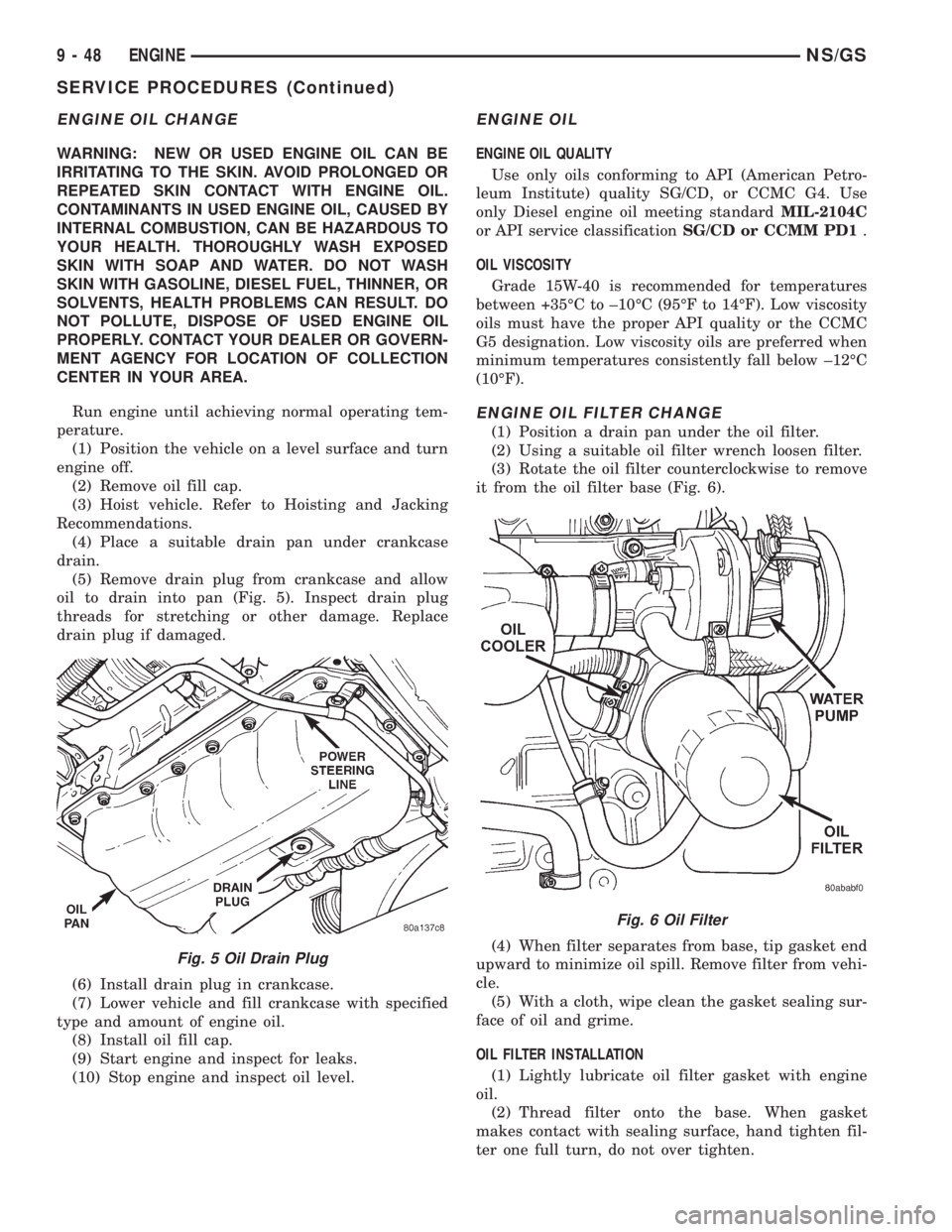
oil to drain into pan (Fig. 5). Inspect drain plug
threads for stretching or other damage. Replace
drain plug if damaged.
(6) Install drain plug in crankcase.
(7) Lower vehicle and fill crankcase with specified
type and amount of engine oil.
(8) Install oil fill cap.
(9) Start engine and inspect for leaks.
(10) Stop engine and inspect oil level.
ENGINE OIL
ENGINE OIL QUALITY
Use only oils conforming to API (American Petro-
leum Institute) quality SG/CD, or CCMC G4. Use
only Diesel engine oil meeting standardMIL-2104C
or API service classificationSG/CD or CCMM PD1.
OIL VISCOSITY
Grade 15W-40 is recommended for temperatures
between +35ÉC to ±10ÉC (95ÉF to 14ÉF). Low viscosity
oils must have the proper API quality or the CCMC
G5 designation. Low viscosity oils are preferred when
minimum temperatures consistently fall below ±12ÉC
(10ÉF).
ENGINE OIL FILTER CHANGE
(1) Position a drain pan under the oil filter.
(2) Using a suitable oil filter wrench loosen filter.
(3) Rotate the oil filter counterclockwise to remove
it from the oil filter base (Fig. 6).
(4) When filter separates from base, tip gasket end
upward to minimize oil spill. Remove filter from vehi-
cle.
(5) With a cloth, wipe clean the gasket sealing sur-
face of oil and grime.
OIL FILTER INSTALLATION
(1) Lightly lubricate oil filter gasket with engine
oil.
(2) Thread filter onto the base. When gasket
makes contact with sealing surface, hand tighten fil-
ter one full turn, do not over tighten.
Fig. 5 Oil Drain Plug
Fig. 6 Oil Filter
9 - 48 ENGINENS/GS
SERVICE PROCEDURES (Continued)
Page 1227 of 1938
(3) Add oil, verify crankcase oil level and start
engine. Inspect filter area for oil leaks.
TIMING PROCEDURE
CAUTION: If a timing gear is removed you must
loosen the rocker arm supports before rotating the
crankshaft or camshaft. This will prevent the valves
hitting the pistons.
For the engine components to be in proper timing
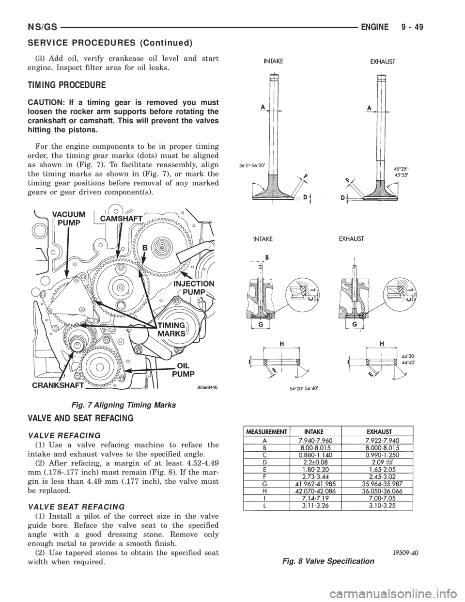
order, the timing gear marks (dots) must be aligned
as shown in (Fig. 7). To facilitate reassembly, align
the timing marks as shown in (Fig. 7), or mark the
timing gear positions before removal of any marked
gears or gear driven component(s).
VALVE AND SEAT REFACING
VALVE REFACING
(1) Use a valve refacing machine to reface the
intake and exhaust valves to the specified angle.
(2) After refacing, a margin of at least 4.52-4.49
mm (.178-.177 inch) must remain (Fig. 8). If the mar-
gin is less than 4.49 mm (.177 inch), the valve must
be replaced.
VALVE SEAT REFACING
(1) Install a pilot of the correct size in the valve
guide bore. Reface the valve seat to the specified
angle with a good dressing stone. Remove only
enough metal to provide a smooth finish.
(2) Use tapered stones to obtain the specified seat
width when required.
Fig. 7 Aligning Timing Marks
Fig. 8 Valve Specification
NS/GSENGINE 9 - 49
SERVICE PROCEDURES (Continued)
Page 1232 of 1938
(28) Remove radiator support bolts.It is neces-
sary to loosen the receiver/dryer to gain access
to the radiator bolts.
(29) Remove radiator and fans as an assembly.
(30) Remove accessory drive belt generator/power
steering. Refer to Group 7, for procedure.
(31) Remove both power steering lines at pump,
and cap both lines.
NOTE: It is not necessary to discharge A/C system
for engine removal.
(32) Remove A/C compressor. Secure compressor
away from engine for clearance during engine
removal.
(33) Remove Generator and adjusting bracket.
NOTE: Do not remove the mounting base from the
generator. It is aligned at the factory and cannot be
realigned in the field.
(34) Hoist vehicle.
(35) Remove exhaust pipe at turbo outlet.
(36) Remove connections at starter.
(37) Remove power steering high pressure line
bracket at rear of oil pan.
(38) Remove both driveshafts from transaxle. Refer
to Group 2, Suspension and Driveshafts.
(39) Disconnect clutch cable at transaxle.
(40) Remove reinforcement plate on lower cross-
member.
(41) Remove front and rear engine mounts. Refer
to procedure outlined in this section.
(42) Drain engine oil and remove oil filter if neces-
sary.
(43) Mount both special tool, engine support brack-
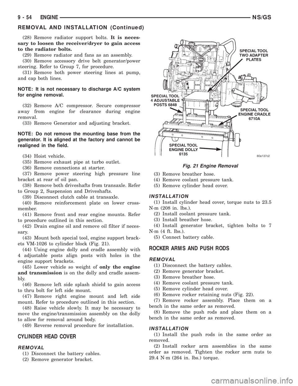
ets VM-1026 to cylinder block (Fig. 21).
(44) Using engine dolly and cradle assembly with
4 adjustable posts align posts with holes in the
engine support brackets.
(45) Lower vehicle so weight ofonly the engine
and transmissionis on the dolly and cradle assem-
bly.
(46) Remove left side splash shield to gain access
to thru bolt for left side mount.
(47) Remove right engine mount and left side
mount. Refer to procedure outlined in this section.
(48) Raise vehicle slowly. It may be necessary to
move the engine/transmission assembly on the dolly
to allow for removal around body.
(49) Reverse removal procedure for installation.
CYLINDER HEAD COVER
REMOVAL
(1) Disconnect the battery cables.
(2) Remove generator bracket.(3) Remove breather hose.
(4) Remove coolant pressure tank.
(5) Remove cylinder head cover.
INSTALLATION
(1) Install cylinder head cover, torque nuts to 23.5
N´m (208 in. lbs.).
(2) Install coolant pressure tank.
(3) Install breather hose.
(4) Install generator bracket, tighten bolts to 7
N´m (4 ft. lbs.).
(5) Connect battery cable.
ROCKER ARMS AND PUSH RODS
REMOVAL
(1) Disconnect the battery cables.
(2) Remove generator bracket.
(3) Remove breather hose.
(4) Remove coolant pressure tank.
(5) Remove cylinder head cover.
(6) Remove rocker retaining nuts (Fig. 22).
(7) Remove rocker assembly. Place them on a
bench in the same order as removed.
(8) Remove the push rods and place them on a
bench in the same order as removed.
INSTALLATION
(1) Install the push rods in the same order as
removed.
(2) Install rocker arm assemblies in the same
order as removed. Tighten the rocker arm nuts to
29.4 N´m (264 in. lbs.) torque.
Fig. 21 Engine Removal
9 - 54 ENGINENS/GS
REMOVAL AND INSTALLATION (Continued)
Page 1246 of 1938
OIL FILTER ADAPTER AND OIL COOLER
REMOVAL
(1) Remove oil filter.
(2) Remove oil cooler adapter bolt.
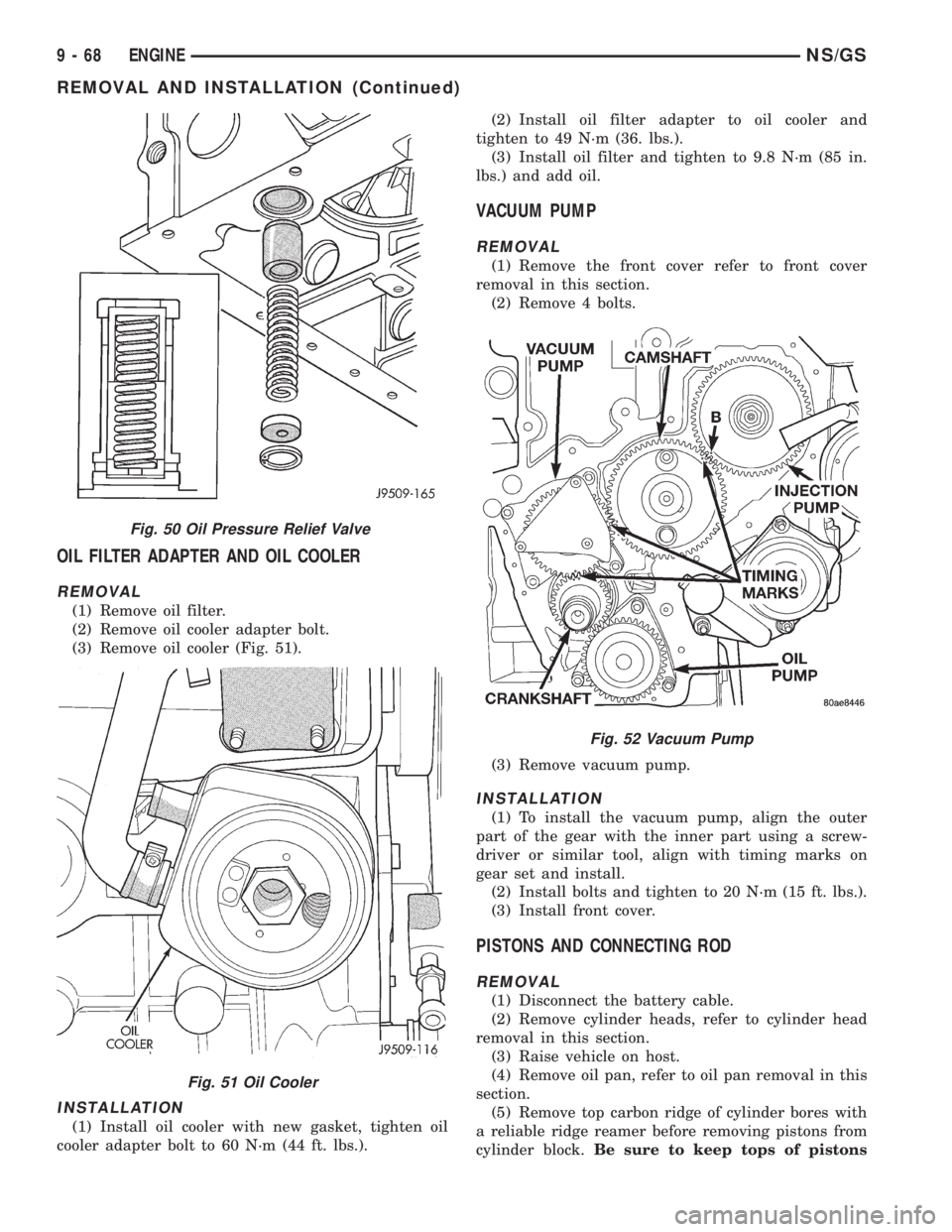
(3) Remove oil cooler (Fig. 51).
INSTALLATION
(1) Install oil cooler with new gasket, tighten oil
cooler adapter bolt to 60 N´m (44 ft. lbs.).(2) Install oil filter adapter to oil cooler and
tighten to 49 N´m (36. lbs.).
(3) Install oil filter and tighten to 9.8 N´m (85 in.
lbs.) and add oil.
VACUUM PUMP
REMOVAL
(1) Remove the front cover refer to front cover
removal in this section.
(2) Remove 4 bolts.
(3) Remove vacuum pump.
INSTALLATION
(1) To install the vacuum pump, align the outer
part of the gear with the inner part using a screw-
driver or similar tool, align with timing marks on
gear set and install.
(2) Install bolts and tighten to 20 N´m (15 ft. lbs.).
(3) Install front cover.
PISTONS AND CONNECTING ROD
REMOVAL
(1) Disconnect the battery cable.
(2) Remove cylinder heads, refer to cylinder head
removal in this section.
(3) Raise vehicle on host.
(4) Remove oil pan, refer to oil pan removal in this
section.
(5) Remove top carbon ridge of cylinder bores with
a reliable ridge reamer before removing pistons from
cylinder block.Be sure to keep tops of pistons
Fig. 50 Oil Pressure Relief Valve
Fig. 51 Oil Cooler
Fig. 52 Vacuum Pump
9 - 68 ENGINENS/GS
REMOVAL AND INSTALLATION (Continued)
Page 1258 of 1938
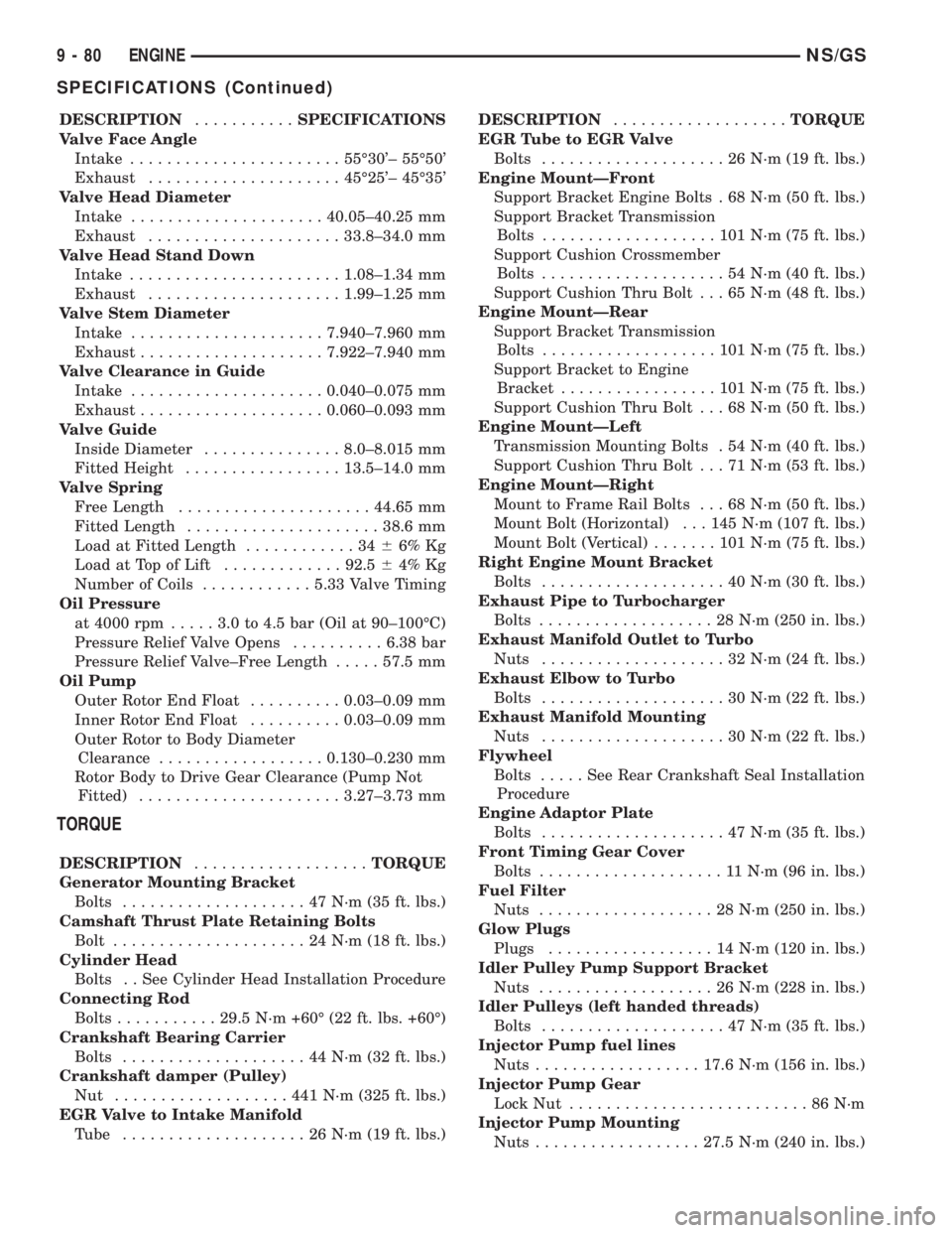
DESCRIPTION...........SPECIFICATIONS
Valve Face Angle
Intake.......................55É30'± 55É50'
Exhaust.....................45É25'± 45É35'
Valve Head Diameter
Intake.....................40.05±40.25 mm
Exhaust.....................33.8±34.0 mm
Valve Head Stand Down
Intake.......................1.08±1.34 mm
Exhaust.....................1.99±1.25 mm
Valve Stem Diameter
Intake.....................7.940±7.960 mm
Exhaust....................7.922±7.940 mm
Valve Clearance in Guide
Intake.....................0.040±0.075 mm
Exhaust....................0.060±0.093 mm
Valve Guide
Inside Diameter...............8.0±8.015 mm
Fitted Height.................13.5±14.0 mm
Valve Spring
Free Length.....................44.65 mm
Fitted Length.....................38.6 mm
Load at Fitted Length............3466% Kg
Load at Top of Lift.............92.564% Kg
Number of Coils............5.33 Valve Timing
Oil Pressure
at 4000 rpm.....3.0to4.5bar(Oil at 90±100ÉC)
Pressure Relief Valve Opens..........6.38 bar
Pressure Relief Valve±Free Length.....57.5 mm
Oil Pump
Outer Rotor End Float..........0.03±0.09 mm
Inner Rotor End Float..........0.03±0.09 mm
Outer Rotor to Body Diameter
Clearance..................0.130±0.230 mm
Rotor Body to Drive Gear Clearance (Pump Not
Fitted)......................3.27±3.73 mm
TORQUE
DESCRIPTION...................TORQUE
Generator Mounting Bracket
Bolts....................47N´m(35ft.lbs.)
Camshaft Thrust Plate Retaining Bolts
Bolt.....................24N´m(18ft.lbs.)
Cylinder Head
Bolts . . See Cylinder Head Installation Procedure
Connecting Rod
Bolts...........29.5 N´m +60É (22 ft. lbs. +60É)
Crankshaft Bearing Carrier
Bolts....................44N´m(32ft.lbs.)
Crankshaft damper (Pulley)
Nut ...................441N´m(325 ft. lbs.)
EGR Valve to Intake Manifold
Tube ....................26N´m(19ft.lbs.)DESCRIPTION...................TORQUE
EGR Tube to EGR Valve
Bolts....................26N´m(19ft.lbs.)
Engine MountÐFront
Support Bracket Engine Bolts . 68 N´m (50 ft. lbs.)
Support Bracket Transmission
Bolts...................101N´m(75ft.lbs.)
Support Cushion Crossmember
Bolts....................54N´m(40ft.lbs.)
Support Cushion Thru Bolt . . . 65 N´m (48 ft. lbs.)
Engine MountÐRear
Support Bracket Transmission
Bolts...................101N´m(75ft.lbs.)
Support Bracket to Engine
Bracket.................101N´m(75ft.lbs.)
Support Cushion Thru Bolt . . . 68 N´m (50 ft. lbs.)
Engine MountÐLeft
Transmission Mounting Bolts . 54 N´m (40 ft. lbs.)
Support Cushion Thru Bolt . . . 71 N´m (53 ft. lbs.)
Engine MountÐRight
Mount to Frame Rail Bolts . . . 68 N´m (50 ft. lbs.)
Mount Bolt (Horizontal) . . . 145 N´m (107 ft. lbs.)
Mount Bolt (Vertical).......101N´m(75ft.lbs.)
Right Engine Mount Bracket
Bolts....................40N´m(30ft.lbs.)
Exhaust Pipe to Turbocharger
Bolts...................28N´m(250 in. lbs.)
Exhaust Manifold Outlet to Turbo
Nuts....................32N´m(24ft.lbs.)
Exhaust Elbow to Turbo
Bolts....................30N´m(22ft.lbs.)
Exhaust Manifold Mounting
Nuts....................30N´m(22ft.lbs.)
Flywheel
Bolts.....SeeRear Crankshaft Seal Installation
Procedure
Engine Adaptor Plate
Bolts....................47N´m(35ft.lbs.)
Front Timing Gear Cover
Bolts....................11N´m(96in.lbs.)
Fuel Filter
Nuts...................28N´m(250 in. lbs.)
Glow Plugs
Plugs..................14N´m(120 in. lbs.)
Idler Pulley Pump Support Bracket
Nuts...................26N´m(228 in. lbs.)
Idler Pulleys (left handed threads)
Bolts....................47N´m(35ft.lbs.)
Injector Pump fuel lines
Nuts..................17.6 N´m (156 in. lbs.)
Injector Pump Gear
Lock Nut..........................86N´m
Injector Pump Mounting
Nuts..................27.5 N´m (240 in. lbs.)
9 - 80 ENGINENS/GS
SPECIFICATIONS (Continued)
Page 1259 of 1938
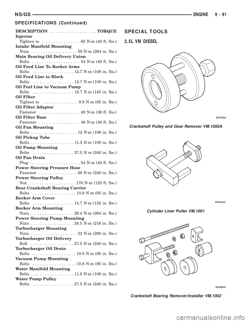
DESCRIPTION...................TORQUE
Injector
Tighten to................65N´m(48ft.lbs.)
Intake Manifold Mounting
Nuts...................30N´m(264 in. lbs.)
Main Bearing Oil Delivery Union
Bolts....................54N´m(40ft.lbs.)
Oil Feed Line To Rocker Arms
Bolts.................12.7 N´m (108 in. lbs.)
Oil Feed Line to Block
Bolts.................12.7 N´m (108 in. lbs.)
Oil Feel Line to Vacuum Pump
Bolts.................16.7 N´m (145 in. lbs.)
Oil Filter
Tighten to...............9.8N´m(85in.lbs.)
Oil Filter Adaptor
Fastener.................49N´m(36ft.lbs.)
Oil Filter Base
Fastener.................49N´m(36ft.lbs.)
Oil Pan Mounting
Bolts...................12N´m(108 in. lbs.)
Oil Pickup Tube
Bolts..................11.3N´m(100 in. lbs.)
Oil Pump Mounting
Bolts.................27.5 N´m (240 in. lbs.)
Oil Pan Drain
Plug.....................54N´m(40ft.lbs.)
Power Steering Pressure Hose
Fastener................28N´m(240 in. lbs.)
Power Steering Pulley
Nut ...................170N´m(125 ft. lbs.)
Rear Crankshaft Bearing Carrier
Bolts..................10.8 N´m (95 in. lbs.)
Rocker Arm Cover
Bolts.................14.7 N´m (132 in. lbs.)
Rocker Arm Mounting
Nuts..................29.4 N´m (264 in. lbs.)
Power Steering Pump Mounting
Nuts..................24.5 N´m (216 in. lbs.)
Turbocharger Mounting
Nuts...................32N´m(288 in. lbs.)
Turbocharger Oil Delivery
Bolt..................27.5 N´m (240 in. lbs.)
Turbocharger Oil Drain
Bolts..................10.8 N´m (95 in. lbs.)
Vacuum Pump Mounting
Bolts..................10.8 N´m (95 in. lbs.)
Water Manifold Mounting
Bolts..................11.8N´m(108 in. lbs.)
Water Pump Pulley
Bolts.................27.5 N´m (240 in. lbs.)SPECIAL TOOLS
2.5L VM DIESEL
Crankshaft Pulley and Gear Remover VM.1000A
Cylinder Liner Puller VM.1001
Crankshaft Bearing Remover/Installer VM.1002
NS/GSENGINE 9 - 81
SPECIFICATIONS (Continued)
Page 1306 of 1938
(9) Momentarily touch the other end of this
jumper wire to the negative terminal of the battery
for no more than 4 seconds.
(10) Place a rag or towel below the fuel line at the
quick connect to the rail.
(11) Disconnect the quick connect fitting to the
rail. Refer to Quick-Connect Fittings in this section.
(12) Return the fuel pump relay to the PDC.
(13) One or more Diagnostic Trouble Codes (DTC's)
may have been stored in the PCM memory due to the
fuel pump relay removal. The DRB scan tool must be
used to erase a DTC. Refer to group 25, On-Board
Diagnostics.
HOSES AND CLAMPS
Inspect all hose connections (clamps and quick con-
nect fittings) for completeness and leaks. Replace
cracked, scuffed, or swelled hoses. Replace hoses that
rub against other vehicle components or show sign of
wear.
Fuel injected vehicles use specially constructed
hoses. When replacing hoses, only use hoses marked
EFM/EFI.
When installing hoses, ensure that they are routed
away from contact with other vehicle components
that could rub against them and cause failure. Avoid
contact with clamps or other components that cause
abrasions or scuffing. Ensure that rubber hoses are
properly routed and avoid heat sources.
The hose clamps have rolled edges to prevent the
clamp from cutting into the hose. Only use clamps
that are original equipment or equivalent. Other
types of clamps may cut into the hoses and cause
high pressure fuel leaks. Tighten hose clamps to 1
N´m (10 in. lbs.) torque.
QUICK-CONNECT FITTINGS
REMOVAL
When disconnecting a quick-connect fitting, the
retainer will remain on the fuel tube nipple.
WARNING: RELEASE FUEL SYSTEM PRESSURE
BEFORE DISCONNECTING A QUICK-CONNECT FIT-
TINGS. REFER TO THE FUEL PRESSURE RELEASE
PROCEDURE.
(1) Disconnect negative cable from battery.
(2) Perform Fuel Pressure Release Procedure.
Refer to the Fuel Pressure Release Procedure in this
section.
(3) Squeeze retainer tabs together and pull fuel
tube/quick-connect fitting assembly off of fuel tube
nipple. The retainer will remain on fuel tube.
INSTALLATION
CAUTION: Never install a quick-connect fitting
without the retainer being either on the fuel tube or
already in the quick-connect fitting. In either case,
ensure the retainer locks securely into the quick-
connect fitting by firmly pulling on fuel tube and fit-
ting to ensure it is secured.
(1) Using a clean lint free cloth, clean the fuel tube
nipple and retainer.
(2) Prior to connecting the fitting to the fuel tube,
coat the fuel tube nipple with clean 30 weight engine
oil.
(3) Push the quick-connect fitting over the fuel
tube until theretainer seats and a click is heard.
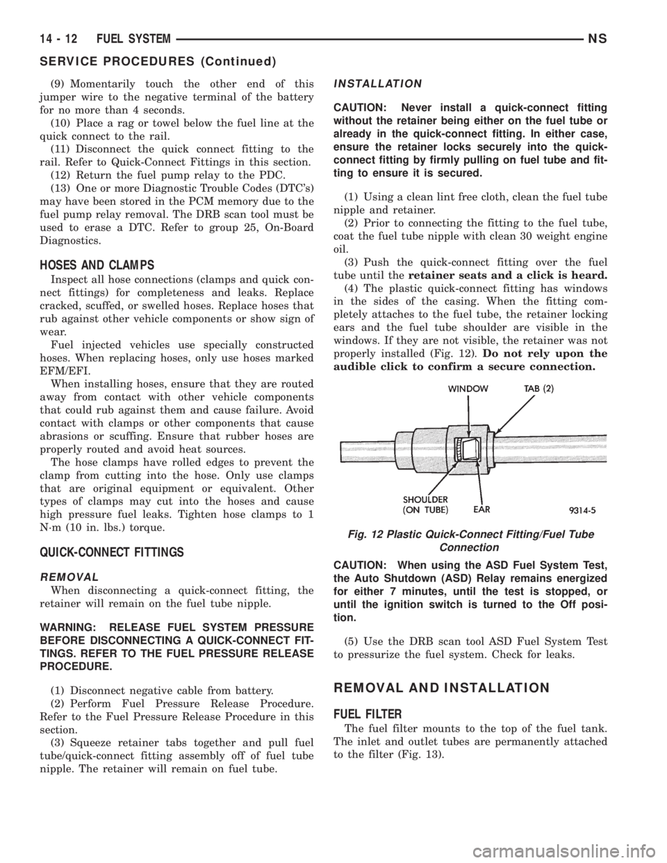
(4) The plastic quick-connect fitting has windows
in the sides of the casing. When the fitting com-
pletely attaches to the fuel tube, the retainer locking
ears and the fuel tube shoulder are visible in the
windows. If they are not visible, the retainer was not
properly installed (Fig. 12).Do not rely upon the
audible click to confirm a secure connection.
CAUTION: When using the ASD Fuel System Test,
the Auto Shutdown (ASD) Relay remains energized
for either 7 minutes, until the test is stopped, or
until the ignition switch is turned to the Off posi-
tion.
(5) Use the DRB scan tool ASD Fuel System Test
to pressurize the fuel system. Check for leaks.
REMOVAL AND INSTALLATION
FUEL FILTER
The fuel filter mounts to the top of the fuel tank.
The inlet and outlet tubes are permanently attached
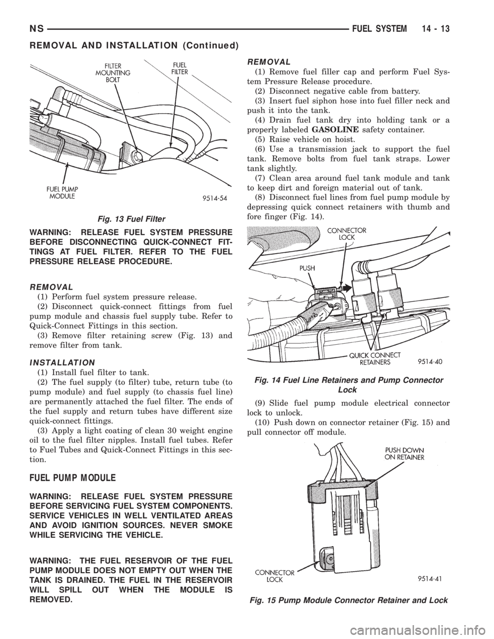
to the filter (Fig. 13).
Fig. 12 Plastic Quick-Connect Fitting/Fuel Tube
Connection
14 - 12 FUEL SYSTEMNS
SERVICE PROCEDURES (Continued)
Page 1307 of 1938
WARNING: RELEASE FUEL SYSTEM PRESSURE
BEFORE DISCONNECTING QUICK-CONNECT FIT-
TINGS AT FUEL FILTER. REFER TO THE FUEL
PRESSURE RELEASE PROCEDURE.
REMOVAL
(1) Perform fuel system pressure release.
(2) Disconnect quick-connect fittings from fuel
pump module and chassis fuel supply tube. Refer to
Quick-Connect Fittings in this section.
(3) Remove filter retaining screw (Fig. 13) and
remove filter from tank.
INSTALLATION
(1) Install fuel filter to tank.
(2) The fuel supply (to filter) tube, return tube (to
pump module) and fuel supply (to chassis fuel line)
are permanently attached the fuel filter. The ends of
the fuel supply and return tubes have different size
quick-connect fittings.
(3) Apply a light coating of clean 30 weight engine
oil to the fuel filter nipples. Install fuel tubes. Refer
to Fuel Tubes and Quick-Connect Fittings in this sec-
tion.
FUEL PUMP MODULE
WARNING: RELEASE FUEL SYSTEM PRESSURE
BEFORE SERVICING FUEL SYSTEM COMPONENTS.
SERVICE VEHICLES IN WELL VENTILATED AREAS
AND AVOID IGNITION SOURCES. NEVER SMOKE
WHILE SERVICING THE VEHICLE.
WARNING: THE FUEL RESERVOIR OF THE FUEL
PUMP MODULE DOES NOT EMPTY OUT WHEN THE
TANK IS DRAINED. THE FUEL IN THE RESERVOIR
WILL SPILL OUT WHEN THE MODULE IS
REMOVED.
REMOVAL
(1) Remove fuel filler cap and perform Fuel Sys-
tem Pressure Release procedure.
(2) Disconnect negative cable from battery.
(3) Insert fuel siphon hose into fuel filler neck and
push it into the tank.
(4) Drain fuel tank dry into holding tank or a
properly labeledGASOLINEsafety container.
(5) Raise vehicle on hoist.
(6) Use a transmission jack to support the fuel
tank. Remove bolts from fuel tank straps. Lower
tank slightly.
(7) Clean area around fuel tank module and tank
to keep dirt and foreign material out of tank.
(8) Disconnect fuel lines from fuel pump module by
depressing quick connect retainers with thumb and
fore finger (Fig. 14).
(9) Slide fuel pump module electrical connector
lock to unlock.
(10) Push down on connector retainer (Fig. 15) and
pull connector off module.
Fig. 13 Fuel Filter
Fig. 14 Fuel Line Retainers and Pump Connector
Lock
Fig. 15 Pump Module Connector Retainer and Lock
NSFUEL SYSTEM 14 - 13
REMOVAL AND INSTALLATION (Continued)