1996 CHRYSLER VOYAGER oil filter
[x] Cancel search: oil filterPage 1111 of 1938
3.0L ENGINE
INDEX
page page
DESCRIPTION AND OPERATION
ENGINE COMPONENTS.................. 61
ENGINE IDENTIFICATION NUMBER......... 61
ENGINE LUBRICATION................... 61
DIAGNOSIS AND TESTING
CHECKING ENGINE OIL PRESSURE......... 62
SERVICE PROCEDURES
AUTO LASH ADJUSTER................... 62
CHECKING CRANKSHAFT END PLAY........ 65
FITTING CONNECTING ROD BEARINGS...... 63
FITTING MAIN BEARING.................. 63
VALVE SERVICE RECONDITION............ 66
REMOVAL AND INSTALLATION
CAMSHAFT SEAL....................... 72
CAMSHAFT............................ 71
CRANKSHAFT.......................... 81
CYLINDER HEAD COVER................. 70
CYLINDER HEAD........................ 73
ENGINE ASSEMBLY...................... 69
ENGINE MOUNTS....................... 68
FRONT CRANKSHAFT OIL SEAL............ 83OIL FILTER AND ADAPTOR................ 84
OILPAN ............................... 77
OIL PUMP............................. 84
PISTON AND CONNECTING ROD........... 78
REAR CRANKSHAFT SEAL................ 83
ROCKER ARMS......................... 72
TIMING BELT........................... 75
DISASSEMBLY AND ASSEMBLY
ROCKER ARMS AND SHAFTS.............. 85
CLEANING AND INSPECTION
CYLINDER BORE........................ 87
CYLINDER HEAD........................ 86
OIL PUMP............................. 87
TIMING BELT........................... 86
ADJUSTMENTS
ENGINE MOUNTS....................... 88
SPECIFICATIONS
3.0L ENGINE........................... 89
TORQUE CHART 3.0L.................... 90
SPECIAL TOOLS
3.0L ENGINE........................... 91
DESCRIPTION AND OPERATION
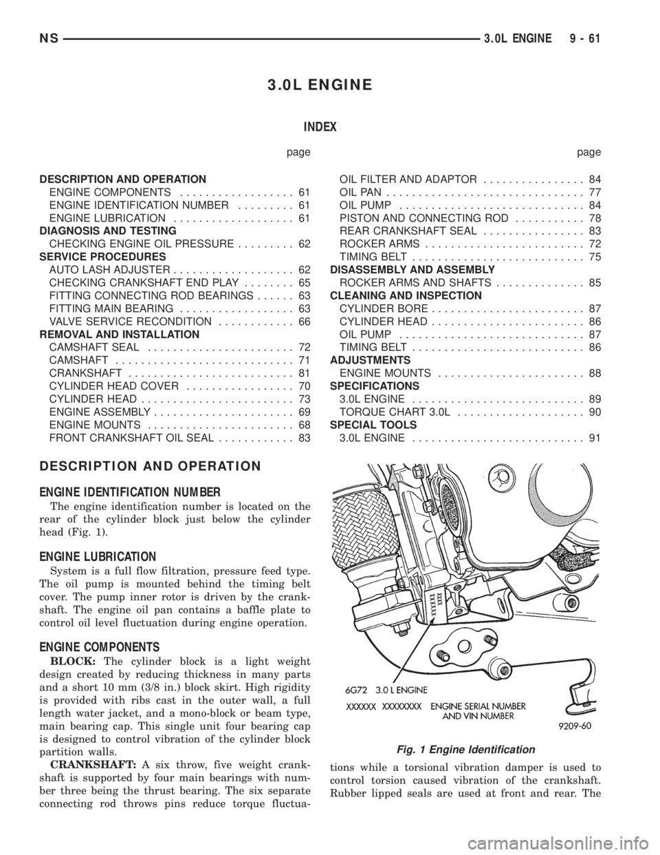
ENGINE IDENTIFICATION NUMBER
The engine identification number is located on the
rear of the cylinder block just below the cylinder
head (Fig. 1).
ENGINE LUBRICATION
System is a full flow filtration, pressure feed type.
The oil pump is mounted behind the timing belt
cover. The pump inner rotor is driven by the crank-
shaft. The engine oil pan contains a baffle plate to
control oil level fluctuation during engine operation.
ENGINE COMPONENTS
BLOCK:The cylinder block is a light weight
design created by reducing thickness in many parts
and a short 10 mm (3/8 in.) block skirt. High rigidity
is provided with ribs cast in the outer wall, a full
length water jacket, and a mono-block or beam type,
main bearing cap. This single unit four bearing cap
is designed to control vibration of the cylinder block
partition walls.
CRANKSHAFT:A six throw, five weight crank-
shaft is supported by four main bearings with num-
ber three being the thrust bearing. The six separate
connecting rod throws pins reduce torque fluctua-tions while a torsional vibration damper is used to
control torsion caused vibration of the crankshaft.
Rubber lipped seals are used at front and rear. The
Fig. 1 Engine Identification
NS3.0L ENGINE 9 - 61
Page 1120 of 1938
(25) Remove ground straps to body.
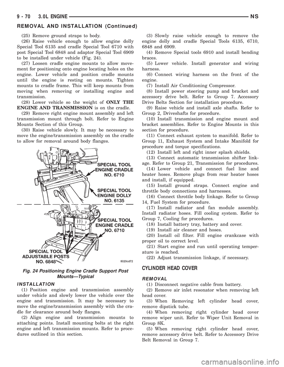
(26) Raise vehicle enough to allow engine dolly
Special Tool 6135 and cradle Special Tool 6710 with
post Special Tool 6848 and adaptor Special Tool 6909
to be installed under vehicle (Fig. 24).
(27) Loosen cradle engine mounts to allow move-
ment for positioning onto engine locating holes on the
engine. Lower vehicle and position cradle mounts
until the engine is resting on mounts. Tighten
mounts to cradle frame. This will keep mounts from
moving when removing or installing engine and
transmission.
(28) Lower vehicle so the weight ofONLY THE
ENGINE AND TRANSMISSIONis on the cradle.
(29) Remove right engine mount assembly and left
transmission mount through bolt. Refer to Engine
Mounts Section of this Group.
(30) Raise vehicle slowly. It may be necessary to
move the engine/transmission assembly on the cradle
to allow for removal around body flanges.
INSTALLATION
(1) Position engine and transmission assembly
under vehicle and slowly lower the vehicle over the
engine and transmission. It may be necessary to
move the engine/transmission assembly with the cra-
dle for clearance around body flanges.
(2) Align engine and transmission mounts to
attaching points. Install mounting bolts at the right
engine and left transmission mounts. Refer to proce-
dures outlined in this section.(3) Slowly raise vehicle enough to remove the
engine dolly and cradle Special Tools 6135, 6710,
6848 and 6909.
(4) Remove Special tools 6910 and install bending
braces.
(5) Lower vehicle. Install generator and wiring
harness.
(6) Connect wiring harness on the front of the
engine.
(7) Install Air Conditioning Compressor.
(8) Install power steering pump and bracket and
accessory drive belt. Refer to Group 7. Accessory
Drive Belts Section for installation procedure.
(9) Raise vehicle and install axle shafts. Refer to
Group 2, Driveshafts for procedure.
(10) Install transmission and engine mount and
bracket assemblies. Refer to Engine Mounts in this
section for procedure.
(11) Connect exhaust system to manifold. Refer to
Group 11, Exhaust System and Intake Manifold for
procedure and torque specifications.
(12) Install left and right inner splash shields.
(13) Connect automatic transmission shifter link-
age. Refer to Group 21, Transmission for procedures.
(14) Lower vehicle and connect fuel line and
heater hoses. Remove plugs from rear heater hoses
and install, if equipped.
(15) Install ground straps. Connect engine and
throttle body connections and harnesses.
(16) Connect throttle body linkage. Refer to Group
14, Fuel System for procedure.
(17) Install radiator and fan module assembly.
Install radiator hoses. Fill cooling system. Refer to
Group 7, Cooling for procedures.
(18) Install battery tray, battery and cover.
(19) Install air cleaner and hoses.
(20) Install oil filter. Fill engine crankcase with
proper oil to correct level.
(21) Start engine and run until operating temper-
ature is reached.
(22) Adjust transmission linkage, if necessary.
CYLINDER HEAD COVER
REMOVAL
(1) Disconnect negative cable from battery.
(2) Remove air inlet resonator when removing left
head cover.
(3) When Removing left cylinder head cover,
remove dipstick tube.
(4) When removing right cylinder head cover
remove wiper unit. Refer to Wiper Unit Removal in
Group 8K.
(5) When removing right cylinder head cover,
remove accessory drive belt. Refer to Accessory Drive
Belt Removal in Group 7.
Fig. 24 Positioning Engine Cradle Support Post
MountsÐTypical
9 - 70 3.0L ENGINENS
REMOVAL AND INSTALLATION (Continued)
Page 1134 of 1938
OIL PUMP
REMOVAL
1. Remove accessory drive belts. Refer to Accessory
Drive Belts Group 7, Cooling System.
2. Remove Timing Belt. Refer to procedure in this
section.
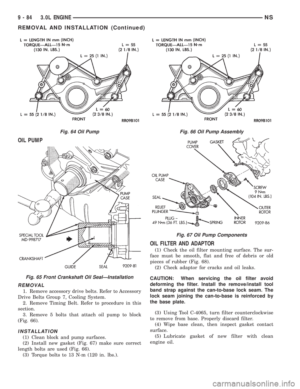
3. Remove 5 bolts that attach oil pump to block
(Fig. 66).
INSTALLATION
(1) Clean block and pump surfaces.
(2) Install new gasket (Fig. 67) make sure correct
length bolts are used (Fig. 66).
(3) Torque bolts to 13 N´m (120 in. lbs.).
OIL FILTER AND ADAPTOR
(1) Check the oil filter mounting surface. The sur-
face must be smooth, flat and free of debris or old
pieces of rubber (Fig. 68).
(2) Check adaptor for cracks and oil leaks.
CAUTION: When servicing the oil filter avoid
deforming the filter. Install the remove/install tool
band strap against the can-to-base lock seam. The
lock seam joining the can-to-base is reinforced by
the base plate.
(3) Using Tool C-4065, turn filter counterclockwise
to remove from base. Properly discard filter.
(4) Wipe base clean, then inspect gasket contact
surface.
(5) Lubricate gasket of new filter with clean
engine oil.
Fig. 64 Oil Pump
Fig. 65 Front Crankshaft Oil SealÐInstallation
Fig. 66 Oil Pump Assembly
Fig. 67 Oil Pump Components
9 - 84 3.0L ENGINENS
REMOVAL AND INSTALLATION (Continued)
Page 1135 of 1938
(6) Install new filter until gasket contacts base.
Tighten filter 1 turn or 20 N´m (15 ft. lbs.). Use filter
wrench if necessary.
(7) Start engine and check for leaks.
DISASSEMBLY AND ASSEMBLY
ROCKER ARMS AND SHAFTS
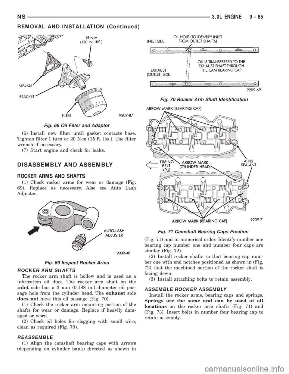
(1) Check rocker arms for wear or damage (Fig.
69). Replace as necessary. Also see Auto Lash
Adjuster.
ROCKER ARM SHAFTS
The rocker arm shaft is hollow and is used as a
lubrication oil duct. The rocker arm shaft on the
inletside hasa3mm(0.188 in.) diameter oil pas-
sage hole from the cylinder head. Theexhaustside
does nothave this oil passage (Fig. 70).
(1) Check the rocker arm mounting portion of the
shafts for wear or damage. Replace if heavily dam-
aged or worn.
(2) Check oil holes for clogging with small wire,
clean as required (Fig. 70).
REASSEMBLE
(1) Align the camshaft bearing caps with arrows
(depending on cylinder bank) directed as shown in(Fig. 71) and in numerical order. Identify number one
bearing cap number one and number four caps are
similar (Fig. 72).
(2) Install rocker shafts so that bearing cap num-
ber one with end notches positioned as shown in (Fig.
72) that the machined portion of the rocker shaft is
facing down.
(3) Install attaching bolts to retain assembly.
ASSEMBLE ROCKER ASSEMBLY
Install the rocker arms, bearing caps and springs.
Springs are the same and can be used at all
locationson the rocker arm shafts (Fig. 71) and
(Fig. 73). Insert bolts in number four bearing cap to
retain assembly.
Fig. 68 Oil Filter and Adaptor
Fig. 69 Inspect Rocker Arms
Fig. 70 Rocker Arm Shaft Identification
Fig. 71 Camshaft Bearing Caps Position
NS3.0L ENGINE 9 - 85
REMOVAL AND INSTALLATION (Continued)
Page 1140 of 1938
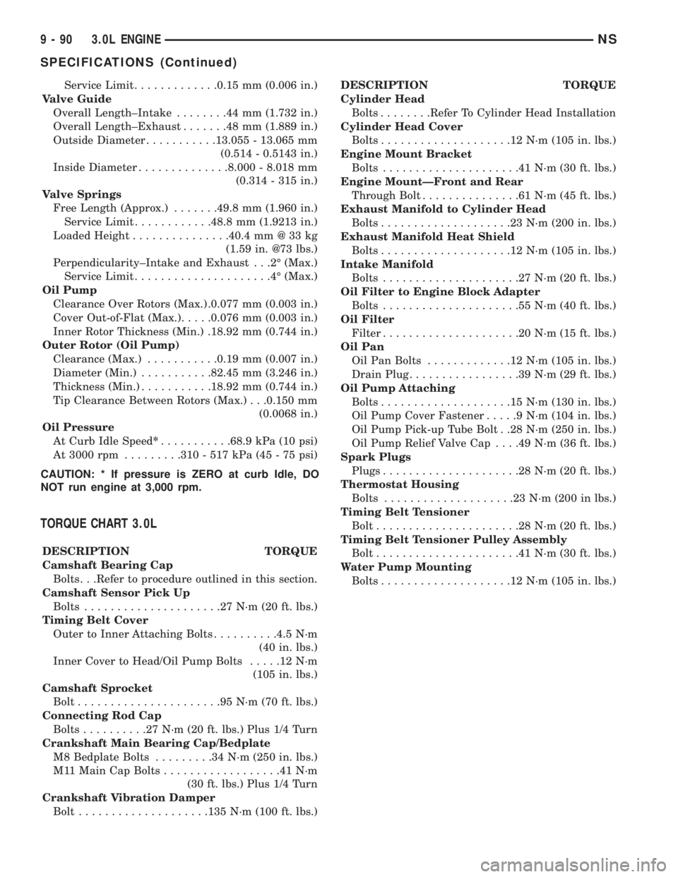
Service Limit.............0.15 mm (0.006 in.)
Valve Guide
Overall Length±Intake........44mm(1.732 in.)
Overall Length±Exhaust.......48mm(1.889 in.)
Outside Diameter...........13.055 - 13.065 mm
(0.514 - 0.5143 in.)
Inside Diameter..............8.000 - 8.018 mm
(0.314 - 315 in.)
Valve Springs
Free Length (Approx.).......49.8 mm (1.960 in.)
Service Limit............48.8 mm (1.9213 in.)
Loaded Height...............40.4 mm @ 33 kg
(1.59 in. @73 lbs.)
Perpendicularity±Intake and Exhaust . . .2É (Max.)
Service Limit.....................4É(Max.)
Oil Pump
Clearance Over Rotors (Max.) .0.077 mm (0.003 in.)
Cover Out-of-Flat (Max.).....0.076 mm (0.003 in.)
Inner Rotor Thickness (Min.) .18.92 mm (0.744 in.)
Outer Rotor (Oil Pump)
Clearance (Max.)...........0.19 mm (0.007 in.)
Diameter (Min.)...........82.45 mm (3.246 in.)
Thickness (Min.)...........18.92 mm (0.744 in.)
Tip Clearance Between Rotors (Max.) . . .0.150 mm
(0.0068 in.)
Oil Pressure
At Curb Idle Speed*...........68.9 kPa (10 psi)
At 3000 rpm.........310 - 517 kPa (45 - 75 psi)
CAUTION: * If pressure is ZERO at curb Idle, DO
NOT run engine at 3,000 rpm.
TORQUE CHART 3.0L
DESCRIPTION TORQUE
Camshaft Bearing Cap
Bolts. . .Refer to procedure outlined in this section.
Camshaft Sensor Pick Up
Bolts.....................27N´m(20ft.lbs.)
Timing Belt Cover
Outer to Inner Attaching Bolts..........4.5 N´m
(40 in. lbs.)
Inner Cover to Head/Oil Pump Bolts.....12N´m
(105 in. lbs.)
Camshaft Sprocket
Bolt......................95N´m(70ft.lbs.)
Connecting Rod Cap
Bolts..........27N´m(20ft.lbs.) Plus 1/4 Turn
Crankshaft Main Bearing Cap/Bedplate
M8 Bedplate Bolts.........34N´m(250 in. lbs.)
M11 Main Cap Bolts..................41N´m
(30 ft. lbs.) Plus 1/4 Turn
Crankshaft Vibration Damper
Bolt....................135 N´m (100 ft. lbs.)DESCRIPTION TORQUE
Cylinder Head
Bolts........Refer To Cylinder Head Installation
Cylinder Head Cover
Bolts....................12N´m(105 in. lbs.)
Engine Mount Bracket
Bolts.....................41N´m(30ft.lbs.)
Engine MountÐFront and Rear
Through Bolt...............61N´m(45ft.lbs.)
Exhaust Manifold to Cylinder Head
Bolts....................23N´m(200 in. lbs.)
Exhaust Manifold Heat Shield
Bolts....................12N´m(105 in. lbs.)
Intake Manifold
Bolts.....................27N´m(20ft.lbs.)
Oil Filter to Engine Block Adapter
Bolts.....................55N´m(40ft.lbs.)
Oil Filter
Filter.....................20N´m(15ft.lbs.)
Oil Pan
Oil Pan Bolts.............12N´m(105 in. lbs.)
Drain Plug.................39N´m(29ft.lbs.)
Oil Pump Attaching
Bolts....................15N´m(130 in. lbs.)
Oil Pump Cover Fastener.....9N´m(104 in. lbs.)
Oil Pump Pick-up Tube Bolt . .28 N´m (250 in. lbs.)
Oil Pump Relief Valve Cap. . . .49 N´m (36 ft. lbs.)
Spark Plugs
Plugs.....................28N´m(20ft.lbs.)
Thermostat Housing
Bolts....................23N´m(200 in lbs.)
Timing Belt Tensioner
Bolt......................28N´m(20ft.lbs.)
Timing Belt Tensioner Pulley Assembly
Bolt......................41N´m(30ft.lbs.)
Water Pump Mounting
Bolts....................12N´m(105 in. lbs.)
9 - 90 3.0L ENGINENS
SPECIFICATIONS (Continued)
Page 1142 of 1938
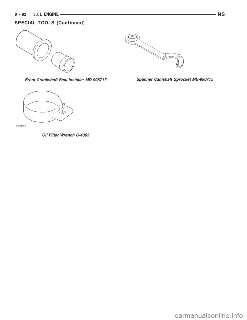
Front Crankshaft Seal Installer MD-998717
Oil Filter Wrench C-4065
Spanner Camshaft Sprocket MB-990775
9 - 92 3.0L ENGINENS
SPECIAL TOOLS (Continued)
Page 1143 of 1938
3.3/3.8L ENGINE
INDEX
page page
DESCRIPTION AND OPERATION
ENGINE COMPONENTS.................. 93
ENGINE IDENTIFICATION................. 93
ENGINE LUBRICATION SYSTEM............ 93
DIAGNOSIS AND TESTING
CHECKING ENGINE OIL PRESSURE......... 96
HYDRAULIC TAPPETS.................... 94
SERVICE PROCEDURES
CRANKSHAFT END PLAY................. 99
FITTING CONNECTING ROD BEARINGS...... 97
FITTING MAIN BEARINGS................. 98
FITTING PISTONS AND RINGS............. 97
MEASURING TIMING CHAIN FOR STRETCH . . . 96
VALVE SERVICE RECONDITION........... 100
VALVE TIMING.......................... 96
REMOVAL AND INSTALLATION
CAMSHAFT BEARINGS.................. 114
CAMSHAFT........................... 113
CRANKSHAFT DAMPER................. 106
CRANKSHAFT OIL SEALÐFRONT.......... 117
CRANKSHAFT OIL SEALÐREAR........... 118
CRANKSHAFT......................... 116
CYLINDER HEAD COVER................ 107
CYLINDER HEAD....................... 108
ENGINE ASSEMBLY..................... 104
ENGINE MOUNTS...................... 102
ENGINE OIL GALLERY PLUGS............. 119OILFILTER ............................ 119
OILPAN .............................. 114
PISTON AND CONNECTING ROD.......... 115
ROCKER ARMS AND SHAFT ASSEMBLY..... 106
TAPPET REMOVAL...................... 110
TIMING CHAIN COVER................... 111
TIMING CHAIN......................... 112
VALVE STEM SEALS OR SPRINGS,
CYLINDER HEAD NOT REMOVED........ 106
VALVES AND VALVE SPRINGS............ 109
WIPER UNIT.......................... 102
DISASSEMBLY AND ASSEMBLY
HYDRAULIC TAPPETS................... 120
OIL PUMP............................ 119
CLEANING AND INSPECTION
CYLINDER HEAD....................... 120
ENGINE BLOCK AND BORE............... 121
OILPAN .............................. 121
OIL PUMP............................ 121
ADJUSTMENTS
ENGINE MOUNTS...................... 123
SPECIFICATIONS
3.3/3.8L ENGINE....................... 123
TORQUE CHART....................... 125
SPECIAL TOOLS
3.3/3.8L ENGINE....................... 127
DESCRIPTION AND OPERATION
ENGINE IDENTIFICATION
The engine identification number is located on the
rear of the cylinder block just below the cylinder
head (Fig. 1).
ENGINE LUBRICATION SYSTEM
The lubrication system is a full flow filtration pres-
sure feed type. Oil from the oil pan is pumped by a
internal gear type oil pump directly coupled to the
crankshaft. The pressure is regulated by a relief
valve located in the chain case cover. The oil is
pumped through an oil filter and feeds a main oil
galley. This oil gallery feeds oil under pressure to the
main and rod bearings, camshaft bearings. Passages
in the cylinder block feed oil to the hydraulic lifters
and rocker shaft brackets which feeds the rocker arm
pivots (Fig. 2).
ENGINE COMPONENTS
ENGINE:The 3.3L (201 Cubic Inches) and 3.8L
(231 Cubic Inches) displacement engines are 60É V
type six cylinder power plants with cast iron cylinder
blocks and aluminum cylinder heads (Fig. 3). Firing
order for these engines is 1-2-3-4-5-6. High turbu-
lence cylinder heads allow a 8.9-1 compression ratio.
CRANKSHAFT:The nodular iron crankshaft is
supported by four main bearings, with number two
being the thrust bearing. Crankshaft end sealing is
provided by front and rear rubber seals.
PISTONS:The pistons are cast aluminum alloy.
Three rings are used. Piston pins, press fitted into
place, join the pistons to forged steel connecting rods.
CAMSHAFT:The nodular iron camshaft is
mounted in four steel backed babbitt bearings. A
thrust plate located in front of the first bearing, and
bolted to the block, controls end play. Silent timing
chain drives the camshaft. This chain is enclosed by
a cast aluminum cover which also carries a front
NS3.3/3.8L ENGINE 9 - 93
Page 1155 of 1938
(20) Remove rear transmission mount and bracket.
(21) Remove power steering pump and bracket
assembly.
(22) Remove wiring harness and connectors from
front of engine.
(23) Remove bending braces and install tool num-
ber 6912 on engine.
(24) Remove transmission inspection cover and
mark flexplate to torque converter.
(25) Remove driveplate to torque converter bolts.
(26) Lower the vehicle.
(27) Remove ground straps to body.
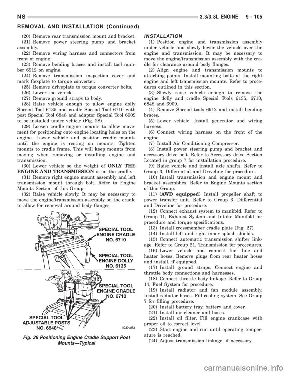
(28) Raise vehicle enough to allow engine dolly
Special Tool 6135 and cradle Special Tool 6710 with
post Special Tool 6848 and adaptor Special Tool 6909
to be installed under vehicle (Fig. 28).
(29) Loosen cradle engine mounts to allow move-
ment for positioning onto engine locating holes on the
engine. Lower vehicle and position cradle mounts
until the engine is resting on mounts. Tighten
mounts to cradle frame. This will keep mounts from
moving when removing or installing engine and
transmission.
(30) Lower vehicle so the weight ofONLY THE
ENGINE AND TRANSMISSIONis on the cradle.
(31) Remove right engine mount assembly and left
transmission mount through bolt. Refer to Engine
Mounts Section of this Group.
(32) Raise vehicle slowly. It may be necessary to
move the engine/transmission assembly on the cradle
to allow for removal around body flanges.INSTALLATION
(1) Position engine and transmission assembly
under vehicle and slowly lower the vehicle over the
engine and transmission. It may be necessary to
move the engine/transmission assembly with the cra-
dle for clearance around body flanges.
(2) Align engine and transmission mounts to
attaching points. Install mounting bolts at the right
engine and left transmission mounts. Refer to proce-
dures outlined in this section.
(3) Slowly raise vehicle enough to remove the
engine dolly and cradle Special Tools 6135, 6710,
6848 and 6909.
(4) Remove Special tools 6912 and install bending
braces.
(5) Lower vehicle. Install generator and wiring
harness.
(6) Connect wiring harness on the front of the
engine.
(7) Install Air Conditioning Compressor.
(8) Install power steering pump and bracket and
accessory drive belt. Refer to Accessory drive Section
Located in group 7 for installation procedure.
(9) Raise vehicle and install axle shafts. Refer to
Group 3, Differential and Driveline for procedure.
(10) Install transmission and engine mount and
bracket assemblies. Refer to Engine Mounts section
of this Group.
(11)(AWD equipped)Install propeller shaft to
power transfer unit. Refer to Group 3, Differential
and Driveline for procedure.
(12) Connect exhaust system to manifold. Refer to
Group 11, Exhaust System and Intake Manifold for
procedure and torque specifications.
(13) Install crossmember cradle plate (Fig. 27).
(14) Install left and right inner splash shields.
(15) Connect automatic transmission shifter link-
age. Refer to Group 21, Transmission for procedures.
(16) Lower vehicle and connect fuel line and
heater hoses. Remove plugs from rear heater hoses
and install, if equipped.
(17) Install ground straps. Connect engine and
throttle body connections and harnesses.
(18) Connect throttle body linkage. Refer to Group
14, Fuel System for procedure.
(19) Install radiator and fan module assembly.
Install radiator hoses. Fill cooling system. See Group
7 for filling procedure.
(20) Install battery tray, battery and cover.
(21) Install air cleaner and hoses.
(22) Install oil filter. Fill engine crankcase with
proper oil to correct level.
(23) Start engine and run until operating temper-
ature is reached.
(24) Adjust transmission linkage, if necessary.
Fig. 28 Positioning Engine Cradle Support Post
MountsÐTypical
NS3.3/3.8L ENGINE 9 - 105
REMOVAL AND INSTALLATION (Continued)