1996 CHRYSLER VOYAGER check engine light
[x] Cancel search: check engine lightPage 548 of 1938

FASTEN SEAT BELT LAMP OR TONE
CONTINUES FOR MORE THAN 10 SECONDS
AFTER SEAT BELTS ARE FASTENED AND
DRIVER'S DOOR IS CLOSED.
(1) Check left door ajar switch for no ground when
switch is depressed.
(a) If continuity replace door ajar switch.
(b) If NO continuity replace BCM for tone condi-
tion, or replace mechanical instrument panel for
lamp condition.
(c) Replace BCM for tone condition.
(d) Replace mechanical instrument cluster for
lamp condition.
NO TONE WHEN PARK OR HEADLAMPS ARE
ON AND DRIVER'S DOOR IS OPEN.
(1) Check left door ajar switch for good ground
when driver's door is open. Repair as necessary.
(2) Inspect BCM connectors and wires for proper
connection. If OK, replace BCM for tone condition.
DOME LAMP ON CHIME
The dome lamp on chime will warn the driver that
the dome lamps have been left on.
With the ignition is OFF:
²Driver's door OPEN (door ajar switch is closed to
ground)
²Dome lamps are ON (dome lamp switch is closed
to ground),
The chime will sound continuously until driver's
door is closed, dome lamps tuned OFF or until the
battery protection time out of 15 minutes has
expired. Refer Group 8L, Lamps proper procedures.
Chime rate: 168 to 192 chimes per minute.
ENGINE TEMPERATURE CRITICAL CHIME
The engine temperature critical chime will warn
the driver that the vehicle's engine is overheating.
While monitoring the coolant temperature, the Pow-
ertrain Control Module (PCM) will send on the CCD
bus as engine temperature every 1.376 seconds to the
Body Control Module (BCM). The BCM calculates
engine temperature and determines if a warning
should occur. This feature is functional only with the
Ignition Switch in the Run/Start position. On the
Diesel vehicles, the coolant temperature sensor is
read directly by the BCM.
When the engine temperature reaches 122ÉC
(252ÉF) or the diesel engine 112ÉC (234ÉF), the BCM
will chime one tone and the engine temperature lamp
comes ON. The BCM turns OFF the lamp when the
engine temperature reaches 117ÉC (242ÉF) or the die-
sel engine 108ÉC (226ÉF). The BCM will chime con-
tinuously when the engine temperature reaches
125ÉC (257ÉF) or diesel engine 116ÉC (241ÉF). The
chime will turn OFF after four minutes or when thetemperature reaches 117ÉC (242ÉF) or diesel engine
108ÉC (226ÉF), which ever occurs first.
EXTERIOR LAMPS ON CHIME
The exterior lamp on chime will warn the driver
that the exterior lights have been left on.
With the ignition switch OFF:
²Driver's door is open (door ajar switch is closed
to ground)
²Parking lamps or headlamps ON (parking lamp
switch is closed to ground)
The chime will sound until lights are turned OFF,
driver's door closed or until the battery protection
time out of 3 minutes has expired.
Refer to Group 8L, Lamps, for proper service pro-
cedures. Chime rate: 168 to 192 chimes per minute.
To test the exterior lamps left on function:
²Turn ignition off
²Remove ignition key
²Turn exterior lamps on with driver's door open.
Chime should sound until lamps are turned off or
driver's door is closed.
KEY-IN IGNITION CHIME
The key-in ignition chime will act as a warning to
the driver that the ignition key has been left in the
ignition switch.
With the ignition switch is in OFF position ONLY:
²Driver's door is open/ajar (door ajar switch is
closed to ground)
²Key is in the ignition switch (key-in ignition
switch is closed to ground)
The chime will sound until one of the above condi-
tions is removed. Chime rate: 168 to 192 chimes per
minute.
To test the key-in ignition function, insert key into
the ignition and open driver's door. Do not turn igni-
tion ON. Chime should sound until key is removed
from ignition or driver's door is closed.
LOW OIL PRESSURE CHIME OPERATION
The low oil pressure chime will warn the driver
that the engine oil pressure is low. The oil pressure
switch, will close to ground during a low oil pressure
condition. The oil pressure lamp will illuminate in
the message center. The body control module will
monitor the oil pressure switch and signal a low oil
pressure condition. A continuous four minute warn-
ing chime will sound and the oil pressure lamp will
come ON when the following conditions are met:
²Ignition on and engine not cranking
²Engine running at 420 to 480 rpm for 10 sec-
onds
²Oil pressure switch closed to ground for (1 sec-
ond minimum, 2 seconds maximum)
Chime rate: 168 to 192 chimes per minute.
8U - 2 CHIME WARNING/REMINDER SYSTEMNS/GS
DIAGNOSIS AND TESTING (Continued)
Page 549 of 1938

SEAT BELT CHIME
The seat belt chime will sound for 4 to 8 seconds,
when the ignition is turned on and the driver's seat
belt is not buckled (seat belt switch is closed to
ground). This is a reminder to the driver to buckle
the seat belt. The seat belt lamp is controlled by the
mechanical instrument cluster. The cluster will also
illuminate the seat belt warning lamp for 6 seconds.
Buckling the driver's seat belt before the time out
has expired will cause the chime to stop immediately.
Chime rate: 38 to 62 chimes per minute.
To test the seat belt warning system, the ignition
switch must be in the OFF position for 1 minute
before starting the test. Turn the ignition switch to
the on position with the driver's seat belt not buck-
led. The seat belt warning lamp should light and the
chime should sound 4 to 8 seconds.
SEAT BELT LAMP
The seat belt lamp in the instrument cluster sig-
nals the vehicle passengers to fasten their seat belts.
The seat belt lamp is illuminated directly by the
instrument cluster for 6 seconds after the instrument
cluster receives the message from the Body Control
Module. The seat belt lamp is therefore illuminated
for 6 seconds whenever the ignition switch is moved
to run/start position.
(1) While ignition is off, the seat belt lamp will not
be illuminated.
(2) The ignition power feed status will be updated
every 250 milliseconds or on change.
(3) This lamp will be checked by the instrument
cluster for 6 seconds with every run/start cycle of the
ignition switch.
TURN SIGNAL ON CHIME
The turn signal on chime will warn the driver that
the turn signals have been left on. When the Body
Control Module receives a turn signal input for 1.6
km (1.0 miles), vehicle speed is greater than 24 km/h
(15 mph), the chime will sound continuously until the
turn signal is turned OFF. If vehicle speed drops
below 24 km/h (15 mph) prior to the warning being
activated, the accumulated distance traveled will be
reset. The turn signal chime is not activated whenthe emergency flashers are turned on. This feature
can also be disabled in EEPROM. Chime rate: 38 to
62 chimes per minute.
For the turn signal warning system to operate:
²Must have input from either the right or left
turn signal lamps. Creates a voltage change between
0 and battery voltage.
²The vehicle speed sensor sends a message to the
Powertrain Control Module that vehicle has exceeded
24 km/h (15 mph) for 1.6 km (1.0 miles).
²When the above two conditions are met, the
chime will sound. The chime will stop when no fur-
ther voltage change is detected.
²If hazard warning signals are pulsing, no chime
will sound.
²If speed drops below 24 km/h (15 mph) before
the warning is issued, the warning will not be issued
and the distance counter will be reset.
²If turn signal lamps are not working properly,
the chime will not sound.
²When using the scan tool, refer to the proper
Body Diagnostic Manual for the procedure.
WARNING LAMP ANNOUNCEMENT CHIME
The warning lamp announcement chime will warn
the driver to scan the instrument cluster to observe
which warning lamp is illuminated. Whenever the
volts, low fuel, low washer fluid, coolant level (gas/
diesel), low coolant level, engine temperature high
(diesel only), door ajar or gate ajar lamps are first
illuminated, the chime will sound one tone. The door/
liftgate ajar warning lamp announcement chime
sounds only if the vehicle speed is above 2 m.p.h.
Two seconds after ignition switch is turned ON or
until the seat belt warning chime ends, all warning
announcement chimes will be consolidated into one
warning announcement. This will occur 2 seconds
after the seat belt warning chime ends. If a warning
announcement should occur while another warning
chime in progress (turn signal, low oil pressure or
high speed warnings), no additional chimes will
sound after the chime in progress ends. All associ-
ated lamps will be illuminated, and the active chime
will be the warning announcement.
NS/GSCHIME WARNING/REMINDER SYSTEM 8U - 3
DIAGNOSIS AND TESTING (Continued)
Page 552 of 1938

THERMOMETER AND COMPASS
THERMOMETER
Engine temperature can increase the displayed
temperature. The CMTC is designed to dampen tem-
perature readings when the vehicle is moving at a
rate slower than 18 miles per hour.
The outside temperature is measured from a sen-
sor mounted in the front of the vehicle. If the tem-
perature is more than 55ÉC (131ÉF) or the
temperature sending line is shorted to ground, the
temperature display should read SC. If the tempera-
ture is less than -40ÉC (-40ÉF), or the sending line is
an open circuit, the display should read OC.
The CMTC will not allow the temperature reading
to increase when the vehicle is not moving.
COMPASS
The CMTC is self calibrating and usually requires
no adjustment. The compass will continuously per-
form a slow calibration to compensate for small mag-
netic variations common to any automobile.
Uncommon magnetic shifts may be caused by items
such as magnetic base antennas, which can perma-
nently alter the magnetic field of the vehicle roof
panel. If excessive magnetic field continues for 5 min-
utes, the compass heading will go blank and only the
CAL symbol will illuminate. When this occurs, the
vehicle roof panel may require demagnetizing. Refer
to the demagnetizing procedure in this section.
Moderate magnetic shifts may, on very rare occa-
sions, cause the compass heading to display only one
or two of the eight possible headings. Although the
compass will eventually compensate for this shift, it
could take several ignition cycles. The compensation
process can be expedited by manually activating the
fast calibration routine. Refer to the fast calibrating
procedure in this section. This procedure may be per-formed anytime that the compass appears to be inac-
curate.
If the calibration data stored in the body control
module is not received, the compass will read only
NE North-East. The CMTC is self calibrating and
requires no adjusting. The word CAL is displayed to
show that the compass is in calibration mode. CAL
will turn off after the vehicle has gone through three
complete circles without stopping, in an area free of
magnetic disturbance. If module displays tempera-
ture while the compass is blank, turn off ignition and
run self diagnostics then demagnetize the vehicle.
After demagnetizing, check compass calibration num-
ber, refer to Self Diagnostic Test. If greater than 15,
demagnetize again until reading is less than 15. If
compass still goes blank after demagnetizing then
check internal diagnostics and demagnetize.
UNIVERSAL TRANSMITTER
The Universal Transmitter, replaces the hand held
remote controls that open the garage door, motorized
gates, or home lighting in/outside the home. This
device memorizes the activator codes for up to three
remote controlled devices. It triggers those devices at
the push of a button, located in a unit permanently
mounted in your overhead console (if equipped).
The transmitter operates off your vehicle's battery
and charging system; no batteries are needed.
The Universal Transmitter incorporates a Rolling
Code technology (random digital code signals from
the remote transmitter) within the transmitter mod-
ule. This is done so, as an added security measure.
Features of the Universal Transmitter are:
²Can be used with most other Radio Frequency
(RF) activated devices.
²Individual channels can be trained.
Fig. 1 Compass Mini-Trip Computer (CMTC)
Switches and Display
Fig. 2 Universal Transmitter Location
8V - 2 OVERHEAD CONSOLENS
DESCRIPTION AND OPERATION (Continued)
Page 1052 of 1938
made to seal the area between the bedplate and cyl-
inder block without disturbing the bearing clearance
or alignment of these components.
GASKET DISASSEMBLY
Parts assembled with form-in-place gaskets may be
disassembled without unusual effort. In some
instances, it may be necessary to lightly tap the part
with a mallet or other suitable tool to break the seal
between the mating surfaces. A flat gasket scraper
may also be lightly tapped into the joint but care
must be taken not to damage the mating surfaces.
SURFACE PREPARATION
Scrape clean or wire brush all gasket surfaces to
remove all loose material. Inspect stamped parts to
ensure gasket rails are flat. Gasket surfaces must be
free of oil and dirt. Make sure old gasket material is
removed from blind attaching holes.
FORM-IN-PLACE GASKET APPLICATION
Assembling parts using a form-in-place gasket
requires care but it's easier then using precut gas-
kets.
MopartGasket Maker material should be applied
sparingly 1 mm (0.040 in.) diameter or less of sealant
to one gasket surface. Be certain the material sur-
rounds each mounting hole. Excess material can eas-
ily be wiped off. Components should be torqued in
place within 15 minutes. The use of a locating dowel
is recommended during assembly to prevent smear-
ing the material off location.
TheMopartSilicone Rubber Adhesive Sealant
gasket material or equivalent should be applied in a
continuous bead approximately 3 mm (0.120 in.) in
diameter. All mounting holes must be circled. For
corner sealing, a 3.17 or 6.35 mm (1/8 or 1/4 in.) drop
is placed in the center of the gasket contact area.
Uncured sealant may be removed with a shop towels.
Components should be torqued in place while the
sealant is still wet to the touch (within 10 minutes).
The usage of a locating dowel is recommended during
assembly to prevent smearing of material off loca-
tion.
CRANKSHAFT SPROCKET BOLT ACCESS PLUG
An Access plug is located in the right inner fender
shield. Remove the plug and insert the proper size
socket, extension and ratchet, when crankshaft rota-
tion is necessary.
ENGINE CORE PLUGS
REMOVAL
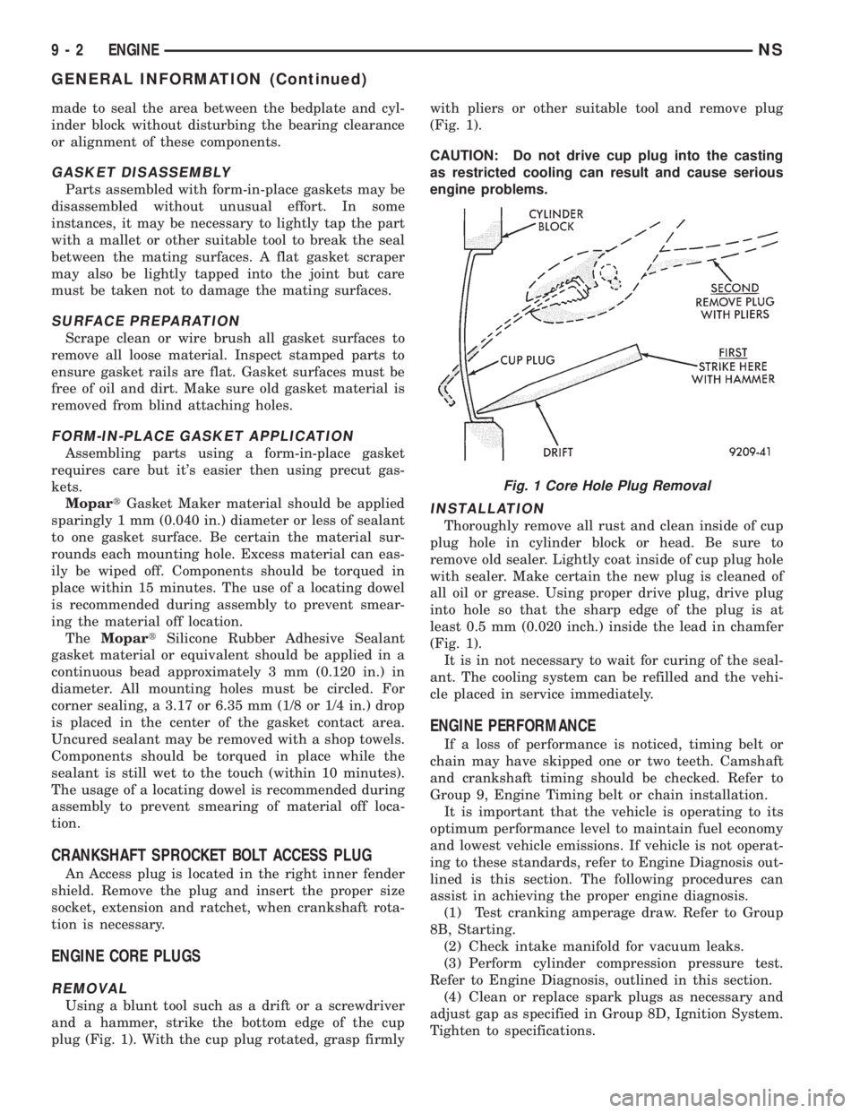
Using a blunt tool such as a drift or a screwdriver
and a hammer, strike the bottom edge of the cup
plug (Fig. 1). With the cup plug rotated, grasp firmlywith pliers or other suitable tool and remove plug
(Fig. 1).
CAUTION: Do not drive cup plug into the casting
as restricted cooling can result and cause serious
engine problems.
INSTALLATION
Thoroughly remove all rust and clean inside of cup
plug hole in cylinder block or head. Be sure to
remove old sealer. Lightly coat inside of cup plug hole
with sealer. Make certain the new plug is cleaned of
all oil or grease. Using proper drive plug, drive plug
into hole so that the sharp edge of the plug is at
least 0.5 mm (0.020 inch.) inside the lead in chamfer
(Fig. 1).
It is in not necessary to wait for curing of the seal-
ant. The cooling system can be refilled and the vehi-
cle placed in service immediately.
ENGINE PERFORMANCE
If a loss of performance is noticed, timing belt or
chain may have skipped one or two teeth. Camshaft
and crankshaft timing should be checked. Refer to
Group 9, Engine Timing belt or chain installation.
It is important that the vehicle is operating to its
optimum performance level to maintain fuel economy
and lowest vehicle emissions. If vehicle is not operat-
ing to these standards, refer to Engine Diagnosis out-
lined is this section. The following procedures can
assist in achieving the proper engine diagnosis.
(1) Test cranking amperage draw. Refer to Group
8B, Starting.
(2) Check intake manifold for vacuum leaks.
(3) Perform cylinder compression pressure test.
Refer to Engine Diagnosis, outlined in this section.
(4) Clean or replace spark plugs as necessary and
adjust gap as specified in Group 8D, Ignition System.
Tighten to specifications.
Fig. 1 Core Hole Plug Removal
9 - 2 ENGINENS
GENERAL INFORMATION (Continued)
Page 1053 of 1938
(5) Test resistance of spark plug cables. Refer to
Group 8D, Ignition System.
(6) Test ignition coils primary and secondary resis-
tance. Replace parts as necessary. Refer to Group 8D,
Ignition System.
(7) Check fuel pump pressure at idle and different
RPM ranges. Refer to Group 14, Fuel System for
Specifications.
(8) The air filter elements should be replaced as
specified in Group 0, Lubrication and Maintenance.
(9) Inspect crankcase ventilation system as out-
lined in Group 25, Emission Control Systems.
(10) Road test vehicle as a final test.
HONING CYLINDER BORES
(1) Used carefully, the cylinder bore resizing hone
C-823 equipped with 220 grit stones, is the best tool
for this job. In addition to deglazing, it will reduce
taper and out-of-round as well as removing light
scuffing, scoring or scratches. Usually a few strokes
will clean up a bore and maintain the required lim-
its.
(2) Deglazing of the cylinder walls may be done
using a cylinder surfacing hone, Tool C-3501,
equipped with 280 grit stones, if the cylinder bore is
straight and round. 20-60 strokes depending on the
bore condition, will be sufficient to provide a satisfac-
tory surface. Inspect cylinder walls after each 20
strokes, using a light honing oil.Do not use engine
or transmission oil, mineral spirits or kerosene.
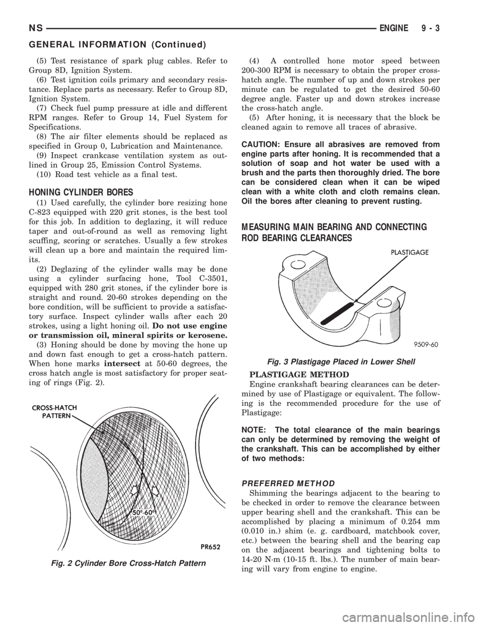
(3) Honing should be done by moving the hone up
and down fast enough to get a cross-hatch pattern.
When hone marksintersectat 50-60 degrees, the
cross hatch angle is most satisfactory for proper seat-
ing of rings (Fig. 2).(4) A controlled hone motor speed between
200-300 RPM is necessary to obtain the proper cross-
hatch angle. The number of up and down strokes per
minute can be regulated to get the desired 50-60
degree angle. Faster up and down strokes increase
the cross-hatch angle.
(5) After honing, it is necessary that the block be
cleaned again to remove all traces of abrasive.
CAUTION: Ensure all abrasives are removed from
engine parts after honing. It is recommended that a
solution of soap and hot water be used with a
brush and the parts then thoroughly dried. The bore
can be considered clean when it can be wiped
clean with a white cloth and cloth remains clean.
Oil the bores after cleaning to prevent rusting.
MEASURING MAIN BEARING AND CONNECTING
ROD BEARING CLEARANCES
PLASTIGAGE METHOD
Engine crankshaft bearing clearances can be deter-
mined by use of Plastigage or equivalent. The follow-
ing is the recommended procedure for the use of
Plastigage:
NOTE: The total clearance of the main bearings
can only be determined by removing the weight of
the crankshaft. This can be accomplished by either
of two methods:
PREFERRED METHOD
Shimming the bearings adjacent to the bearing to
be checked in order to remove the clearance between
upper bearing shell and the crankshaft. This can be
accomplished by placing a minimum of 0.254 mm
(0.010 in.) shim (e. g. cardboard, matchbook cover,
etc.) between the bearing shell and the bearing cap
on the adjacent bearings and tightening bolts to
14-20 N´m (10-15 ft. lbs.). The number of main bear-
ing will vary from engine to engine.
Fig. 2 Cylinder Bore Cross-Hatch Pattern
Fig. 3 Plastigage Placed in Lower Shell
NSENGINE 9 - 3
GENERAL INFORMATION (Continued)
Page 1059 of 1938
(2) Add an oil soluble dye (use as recommended by
manufacturer). Start the engine and let idle for
approximately 15 minutes. Check the oil dipstick to
make sure the dye is thoroughly mixed as indicated
with a bright yellow color under a black light.
(3) Using a black light, inspect the entire engine
for fluorescent dye, particularly at the suspected area
of oil leak. If the oil leak is found and identified,
repair per service manual instructions.
(4) If dye is not observed, drive the vehicle at var-
ious speeds for approximately 24km (15 miles), and
repeat inspection.
(5)If the oil leak source is not positively
identified at this time, proceed with the air leak
detection test method as follows:
(6) Disconnect the fresh air hose (makeup air) at
the cylinder head cover and plug or cap the nipple on
the cover.
(7) Remove the PCV valve hose from the cylinder
head cover. Cap or plug the PCV valve nipple on the
cover.
(8) Attach an air hose with pressure gauge and
regulator to the dipstick tube.
CAUTION: Do not subject the engine assembly to
more than 20.6 kpa (3 PSI) of test pressure.
(9) Gradually apply air pressure from 1 psi to 2.5
psi maximum while applying soapy water at the sus-
pected source. Adjust the regulator to the suitable
test pressure that provide the best bubbles which
will pinpoint the leak source. If the oil leak is
detected and identified, repair per service manual
procedures.
(10) If the leakage occurs at the rear oil seal area,
refer to the section, Inspection for Rear Seal Area
Leak.
(11) If no leaks are detected, turn off the air sup-
ply and remove the air hose and all plugs and caps.
Install the PCV valve and breather cap hose. Proceed
to next step.
(12) Clean the oil off the suspect oil leak area
using a suitable solvent. Drive the vehicle at various
speeds approximately 24 km (15 miles). Inspect the
engine for signs of an oil leak by using a black light.INSPECTION FOR REAR SEAL AREA LEAKS
Since it is sometimes difficult to determine the
source of an oil leak in the rear seal area of the
engine, a more involved inspection is necessary. The
following steps should be followed to help pinpoint
the source of the leak.
If the leakage occurs at the crankshaft rear oil seal
area:
(1) Disconnect the battery.
(2) Raise the vehicle.
(3) Remove torque converter or clutch housing
cover and inspect rear of block for evidence of oil.
Use a black light to check for the oil leak. If a leak is
present in this area remove transmission for further
inspection.
(a) Circular spray pattern generally indicates
seal leakage or crankshaft damage.
(b) Where leakage tends to run straight down,
possible causes are a porous block, oil galley cup
plug, bedplate to cylinder block mating surfaces
and seal bore. See proper repair procedures for
these items.
(4) If no leaks are detected, pressurized the crank-
case as outlined in the, Inspection (Engine oil Leaks
in general)
CAUTION: Do not exceed 20.6 kPa (3 psi).
(5) If the leak is not detected, very slowly turn the
crankshaft and watch for leakage. If a leak is
detected between the crankshaft and seal while
slowly turning the crankshaft, it is possible the
crankshaft seal surface is damaged. The seal area on
the crankshaft could have minor nicks or scratches
that can be polished out with emery cloth.
CAUTION: Use extreme caution when crankshaft
polishing is necessary to remove minor nicks and
scratches. The crankshaft seal flange is especially
machined to complement the function of the rear oil
seal.
(6) For bubbles that remain steady with shaft
rotation, no further inspection can be done until dis-
assembled.
(7) After the oil leak root cause and appropriate
corrective action have been identified. Refer to Rear
Crankshaft Seals, for proper replacement procedures.
NSENGINE 9 - 9
DIAGNOSIS AND TESTING (Continued)
Page 1072 of 1938
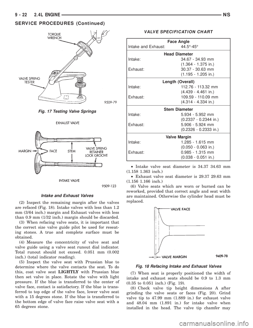
(2) Inspect the remaining margin after the valves
are refaced (Fig. 18). Intake valves with less than 1.2
mm (3/64 inch.) margin and Exhaust valves with less
than 0.9 mm (1/32 inch.) margin should be discarded.
(3) When refacing valve seats, it is important that
the correct size valve guide pilot be used for reseat-
ing stones. A true and complete surface must be
obtained.
(4) Measure the concentricity of valve seat and
valve guide using a valve seat runout dial indicator.
Total runout should not exceed. 0.051 mm (0.002
inch.) (total indicator reading).
(5) Inspect the valve seat with Prussian blue to
determine where the valve contacts the seat. To do
this, coat valve seatLIGHTLYwith Prussian blue
then set valve in place. Rotate the valve with light
pressure. If the blue is transferred to the center of
valve face, contact is satisfactory. If the blue is trans-
ferred to top edge of the valve face, lower valve seat
with a 15 degrees stone. If the blue is transferred to
the bottom edge of valve face raise valve seat with a
65 degrees stone.²Intake valve seat diameter is 34.37 34.63 mm
(1.158 1.363 inch.)
²Exhaust valve seat diameter is 29.37 29.63 mm
(1.156 1.166 inch.)
(6) Valve seats which are worn or burned can be
reworked, provided that correct angle and seat width
are maintained. Otherwise the cylinder head must be
replaced.
(7) When seat is properly positioned the width of
intake and exhaust seats should be 0.9 to 1.3 mm
(0.35 to 0.051 inch.) (Fig. 19).
(8) Check valve tip height dimensions A after
grinding the valve seats or faces (Fig. 20). Grind
valve tip to 47.99 mm (1.889 in.) for exhaust valve
and 48.04 mm (1.891 in.) for intake valve when
installed in the head. The valve tip chamfer may
Fig. 17 Testing Valve Springs
Intake and Exhaust Valves
VALVE SPECIFICATION CHART
Face Angle
Intake and Exhaust: 44.5É-45É
Head Diameter
Intake: 34.67 - 34.93 mm
(1.364 - 1.375 in.)
Exhaust: 30.37 - 30.63 mm
(1.195 - 1.205 in.)
Length (Overall)
Intake: 112.76 - 113.32 mm
(4.439 - 4.461 in.)
Exhaust: 109.59 - 110.09 mm
(4.314 - 4.334 in.)
Stem Diameter
Intake: 5.934 - 5.952 mm
(0.2337 - 0.2344 in.)
Exhaust: 5.906 - 5.924 mm
(0.2326 - 0.2333 in.)
Valve Margin
Intake: 1.285 - 1.615 mm
(0.050 - 0.063 in.)
Exhaust: 0.985 - 1.315 mm
(0.038 - 0.051 in.)
Fig. 18 Refacing Intake and Exhaust Valves
9 - 22 2.4L ENGINENS
SERVICE PROCEDURES (Continued)
Page 1111 of 1938
3.0L ENGINE
INDEX
page page
DESCRIPTION AND OPERATION
ENGINE COMPONENTS.................. 61
ENGINE IDENTIFICATION NUMBER......... 61
ENGINE LUBRICATION................... 61
DIAGNOSIS AND TESTING
CHECKING ENGINE OIL PRESSURE......... 62
SERVICE PROCEDURES
AUTO LASH ADJUSTER................... 62
CHECKING CRANKSHAFT END PLAY........ 65
FITTING CONNECTING ROD BEARINGS...... 63
FITTING MAIN BEARING.................. 63
VALVE SERVICE RECONDITION............ 66
REMOVAL AND INSTALLATION
CAMSHAFT SEAL....................... 72
CAMSHAFT............................ 71
CRANKSHAFT.......................... 81
CYLINDER HEAD COVER................. 70
CYLINDER HEAD........................ 73
ENGINE ASSEMBLY...................... 69
ENGINE MOUNTS....................... 68
FRONT CRANKSHAFT OIL SEAL............ 83OIL FILTER AND ADAPTOR................ 84
OILPAN ............................... 77
OIL PUMP............................. 84
PISTON AND CONNECTING ROD........... 78
REAR CRANKSHAFT SEAL................ 83
ROCKER ARMS......................... 72
TIMING BELT........................... 75
DISASSEMBLY AND ASSEMBLY
ROCKER ARMS AND SHAFTS.............. 85
CLEANING AND INSPECTION
CYLINDER BORE........................ 87
CYLINDER HEAD........................ 86
OIL PUMP............................. 87
TIMING BELT........................... 86
ADJUSTMENTS
ENGINE MOUNTS....................... 88
SPECIFICATIONS
3.0L ENGINE........................... 89
TORQUE CHART 3.0L.................... 90
SPECIAL TOOLS
3.0L ENGINE........................... 91
DESCRIPTION AND OPERATION
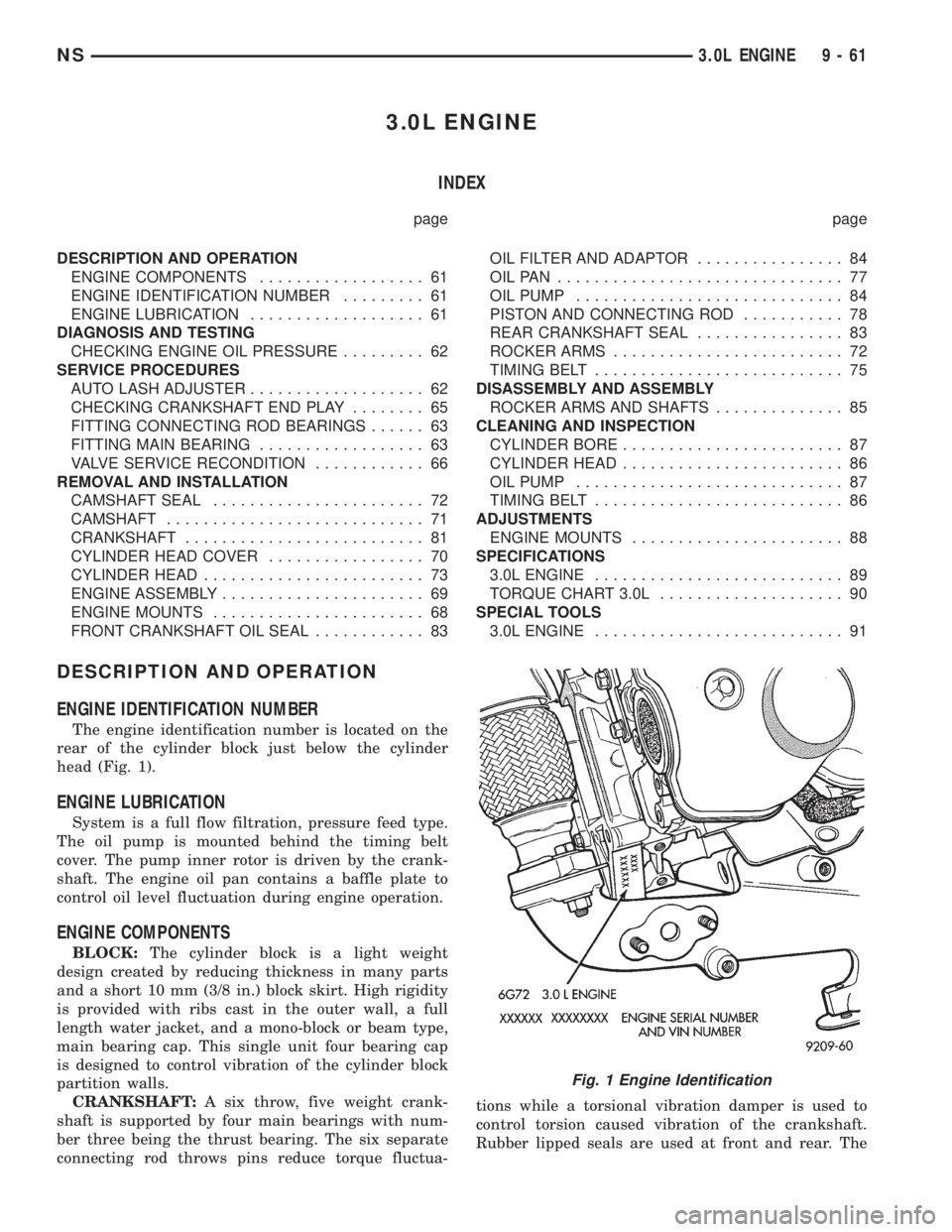
ENGINE IDENTIFICATION NUMBER
The engine identification number is located on the
rear of the cylinder block just below the cylinder
head (Fig. 1).
ENGINE LUBRICATION
System is a full flow filtration, pressure feed type.
The oil pump is mounted behind the timing belt
cover. The pump inner rotor is driven by the crank-
shaft. The engine oil pan contains a baffle plate to
control oil level fluctuation during engine operation.
ENGINE COMPONENTS
BLOCK:The cylinder block is a light weight
design created by reducing thickness in many parts
and a short 10 mm (3/8 in.) block skirt. High rigidity
is provided with ribs cast in the outer wall, a full
length water jacket, and a mono-block or beam type,
main bearing cap. This single unit four bearing cap
is designed to control vibration of the cylinder block
partition walls.
CRANKSHAFT:A six throw, five weight crank-
shaft is supported by four main bearings with num-
ber three being the thrust bearing. The six separate
connecting rod throws pins reduce torque fluctua-tions while a torsional vibration damper is used to
control torsion caused vibration of the crankshaft.
Rubber lipped seals are used at front and rear. The
Fig. 1 Engine Identification
NS3.0L ENGINE 9 - 61