1996 CHRYSLER VOYAGER check engine light
[x] Cancel search: check engine lightPage 1225 of 1938
HYDRAULIC TAPPETS
Before disassembling any part of the engine to cor-
rect tappet noise, check the oil pressure. If vehicle
has no oil pressure gauge, install a reliable gauge at
the pressure sending unit. The pressure should be
between 3.5 bars to 5.0 bars at 4000 RPM.
Check the oil level after the engine reaches normal
operating temperature. Allow 5 minutes to stabilize
oil level, check dipstick. The oil level in the pan
should never be above the FULL mark or below the
ADD OIL mark on dipstick. Either of these 2 condi-
tions could be responsible for noisy tappets.
OIL LEVEL HIGH
If oil level is above the FULL mark, it is possible
for the connecting rods to dip into the oil. With the
engine running, this condition could create foam in
the oil pan. Foam in oil pan would be fed to the
hydraulic tappets by the oil pump causing them to
lose length and allow valves to seat noisily.
OIL LEVEL LOW
Low oil level may allow oil pump to take in air.
When air is fed to the tappets, they lose length which
allows valves to seat noisily. Any leaks on intake side
of oil pump through which air can be drawn will cre-
ate the same tappet action. Check the lubrication
system from the intake strainer to the pump cover,
including the relief valve retainer cap. When tappet
noise is due to aeration, it may be intermittent or
constant, and usually more than 1 tappet will be
noisy. When oil level and leaks have been corrected,
operate the engine at fast idle. Run engine for a suf-
ficient time to allow all of the air inside the tappets
to be bled out.
TAPPET NOISE DIAGNOSIS
(1) To determine source of tappet noise, operate
engine at idle with cylinder head covers removed.
(2) Feel each valve spring or rocker arm to detect
noisy tappet. The noisy tappet will cause the affected
spring and/or rocker arm to vibrate or feel rough in
operation.
NOTE: Worn valve guides or cocked springs are
sometimes mistaken for noisy tappets. If such is
the case, noise may be dampened by applying side
thrust on the valve spring. If noise is not apprecia-
bly reduced, it can be assumed the noise is in the
tappet. Inspect the rocker arm push rod sockets
and push rod ends for wear.
(3) Valve tappet noise ranges from light noise to a
heavy click. A light noise is usually caused by exces-
sive leak down around the unit plunger or by the
plunger partially sticking in the tappet body cylinder.
The tappet should be replaced. A heavy click iscaused by a tappet check valve not seating or by for-
eign particles becoming wedged between the plunger
and the tappet body. This will cause the plunger to
stick in the down position. This heavy click will be
accompanied by excessive clearance between the
valve stem and rocker arm as valve closes. In either
case, tappet assembly should be removed for inspec-
tion and cleaning.
(4) The valve train generates a noise very much
like a light tappet noise during normal operation.
Care must be taken to ensure that tappets are mak-
ing the noise. In general, if more than one tappet
seems to be noisy, its probably not the tappets.
SERVICE PROCEDURES
CHECKING OIL LEVEL
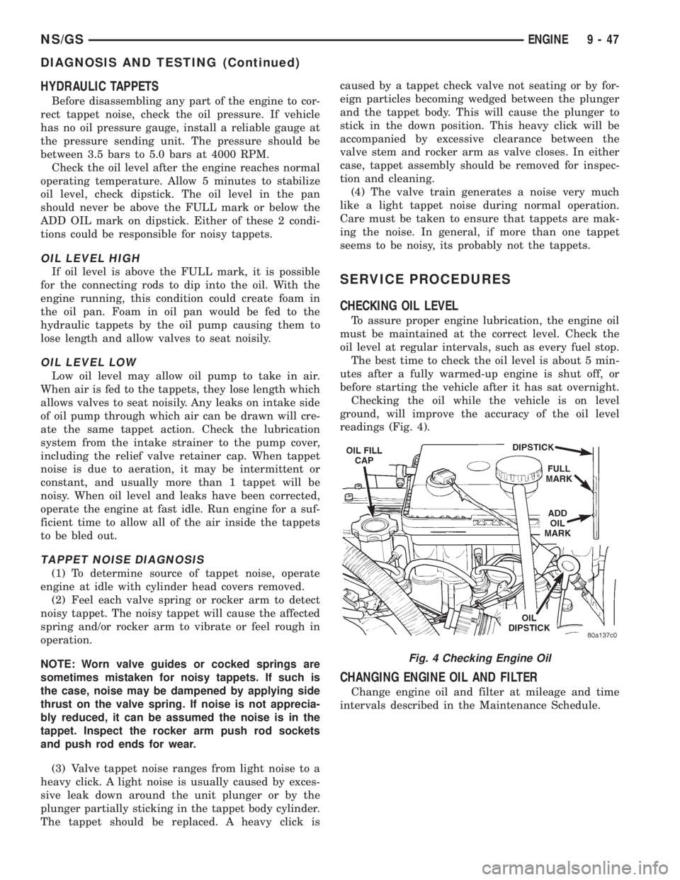
To assure proper engine lubrication, the engine oil
must be maintained at the correct level. Check the
oil level at regular intervals, such as every fuel stop.
The best time to check the oil level is about 5 min-
utes after a fully warmed-up engine is shut off, or
before starting the vehicle after it has sat overnight.
Checking the oil while the vehicle is on level
ground, will improve the accuracy of the oil level
readings (Fig. 4).
CHANGING ENGINE OIL AND FILTER
Change engine oil and filter at mileage and time
intervals described in the Maintenance Schedule.
Fig. 4 Checking Engine Oil
NS/GSENGINE 9 - 47
DIAGNOSIS AND TESTING (Continued)
Page 1252 of 1938
retainer and plunger spring. Check valve could be
flat or ball.
Assemble tappets in reverse order.
CLEANING AND INSPECTION
CYLINDER HEAD COVERS
Remove any original sealer from the cover sealing
surface of the engine cylinder head.
Remove all residue from the sealing surface using
a clean, dry cloth.
ROCKER ARMS AND PUSH RODS
CLEANING
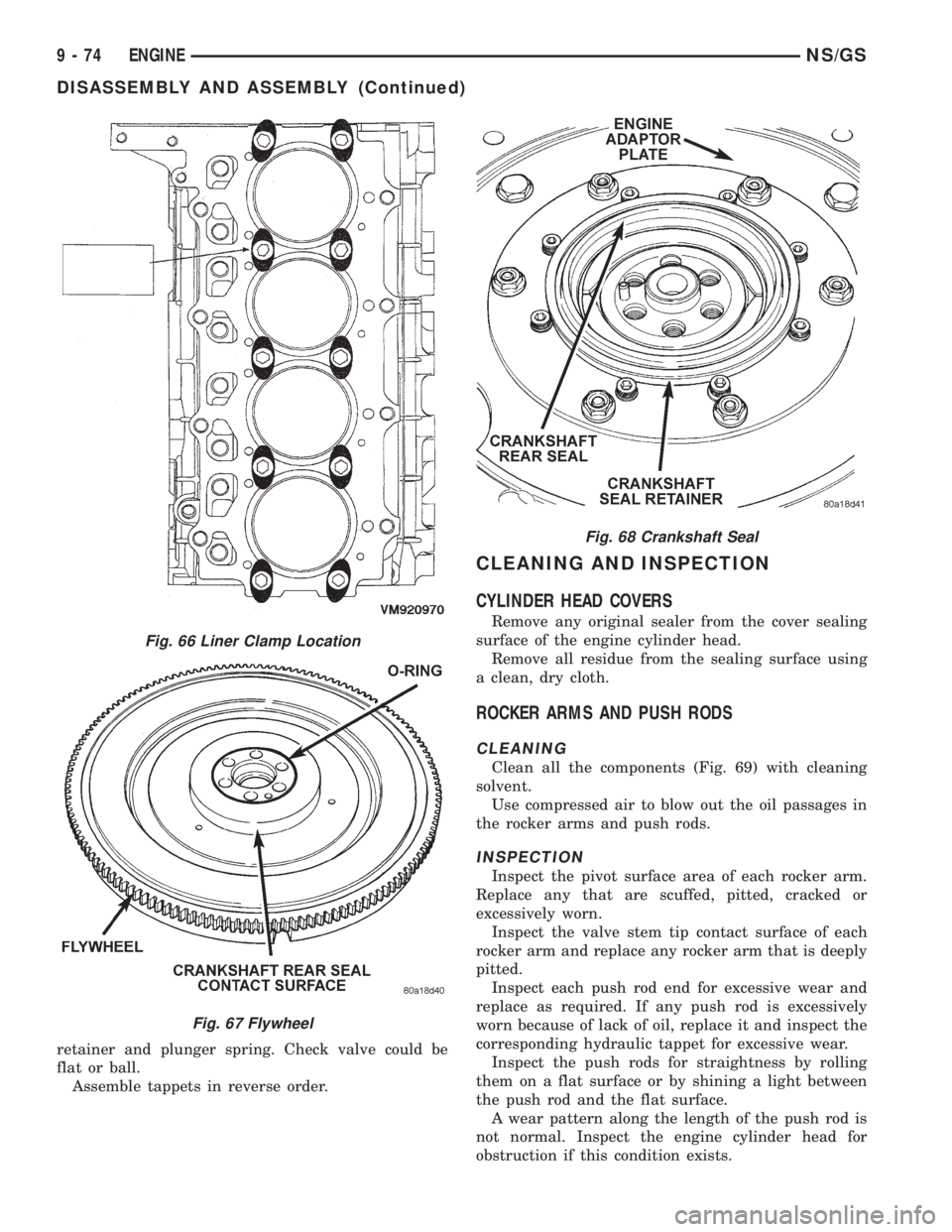
Clean all the components (Fig. 69) with cleaning
solvent.
Use compressed air to blow out the oil passages in
the rocker arms and push rods.
INSPECTION
Inspect the pivot surface area of each rocker arm.
Replace any that are scuffed, pitted, cracked or
excessively worn.
Inspect the valve stem tip contact surface of each
rocker arm and replace any rocker arm that is deeply
pitted.
Inspect each push rod end for excessive wear and
replace as required. If any push rod is excessively
worn because of lack of oil, replace it and inspect the
corresponding hydraulic tappet for excessive wear.
Inspect the push rods for straightness by rolling
them on a flat surface or by shining a light between
the push rod and the flat surface.
A wear pattern along the length of the push rod is
not normal. Inspect the engine cylinder head for
obstruction if this condition exists.
Fig. 66 Liner Clamp Location
Fig. 67 Flywheel
Fig. 68 Crankshaft Seal
9 - 74 ENGINENS/GS
DISASSEMBLY AND ASSEMBLY (Continued)
Page 1255 of 1938
(3.6196-3.6200 in.). Maximum wear limit .05mm
(.0019 in.).
(2) Check piston pin bores in piston for roundness.
Make 3 checks at 120É intervals. Maximum out of
roundness .05mm (.0019in.).
(3) The piston diameter should be measured
approximately 15 mm (.590 in.) up from the base.
(4) Skirt wear should not exceed 0.1 mm (.00039
in.).
(5) The clearance between the cylinder liner and
piston should not exceed 0.25 mm (.0009 in.).
(6) Make sure the weight of the pistons does not
differ by more than 5 g.
CONNECTING ROD
(1) Assemble bearing shells and bearing caps to
their respective connecting rods ensuring that the
serrations on the cap and reference marks are
aligned.
(2) Tighten bearing cap bolts to 29 N´m (21 ft. lbs.)
plus 60É.
(3) Check and record internal diameter of crank
end of connecting rod.
Note: When changing connecting rods, all four
must have the same weight and be stamped with the
same number.Replacement connecting rods will
only be supplied in sets of four.
(4) Connecting rods are supplied in sets of four
since they all must be of the same weight category.
Max allowable weight difference is 18 gr.NOTE:On
one side of the big end of the con-rod there is a two-
digit number which refers to the weight category. On
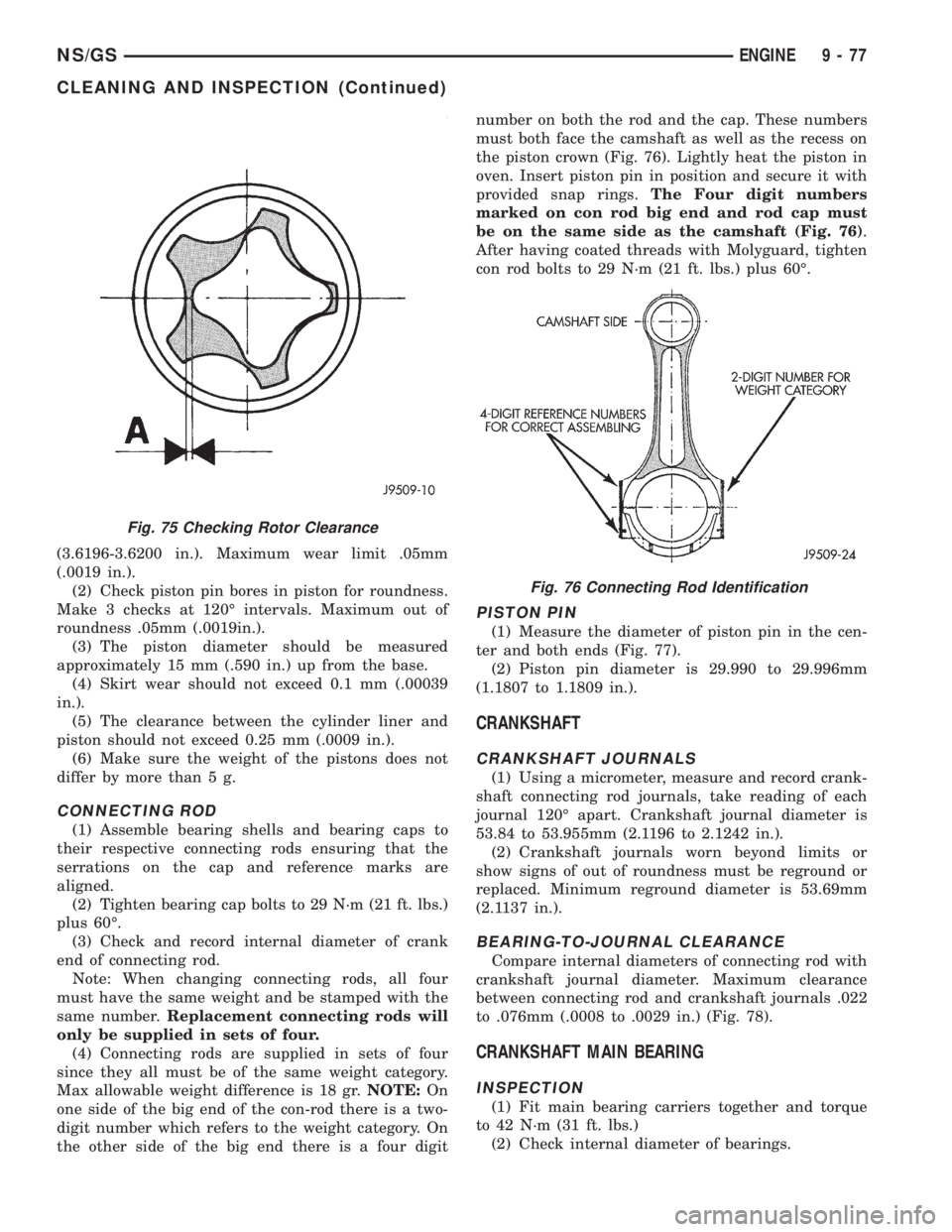
the other side of the big end there is a four digitnumber on both the rod and the cap. These numbers
must both face the camshaft as well as the recess on
the piston crown (Fig. 76). Lightly heat the piston in
oven. Insert piston pin in position and secure it with
provided snap rings.The Four digit numbers
marked on con rod big end and rod cap must
be on the same side as the camshaft (Fig. 76).
After having coated threads with Molyguard, tighten
con rod bolts to 29 N´m (21 ft. lbs.) plus 60É.
PISTON PIN
(1) Measure the diameter of piston pin in the cen-
ter and both ends (Fig. 77).
(2) Piston pin diameter is 29.990 to 29.996mm
(1.1807 to 1.1809 in.).
CRANKSHAFT
CRANKSHAFT JOURNALS
(1) Using a micrometer, measure and record crank-
shaft connecting rod journals, take reading of each
journal 120É apart. Crankshaft journal diameter is
53.84 to 53.955mm (2.1196 to 2.1242 in.).
(2) Crankshaft journals worn beyond limits or
show signs of out of roundness must be reground or
replaced. Minimum reground diameter is 53.69mm
(2.1137 in.).
BEARING-TO-JOURNAL CLEARANCE
Compare internal diameters of connecting rod with
crankshaft journal diameter. Maximum clearance
between connecting rod and crankshaft journals .022
to .076mm (.0008 to .0029 in.) (Fig. 78).
CRANKSHAFT MAIN BEARING
INSPECTION
(1) Fit main bearing carriers together and torque
to 42 N´m (31 ft. lbs.)
(2) Check internal diameter of bearings.
Fig. 75 Checking Rotor Clearance
Fig. 76 Connecting Rod Identification
NS/GSENGINE 9 - 77
CLEANING AND INSPECTION (Continued)
Page 1308 of 1938
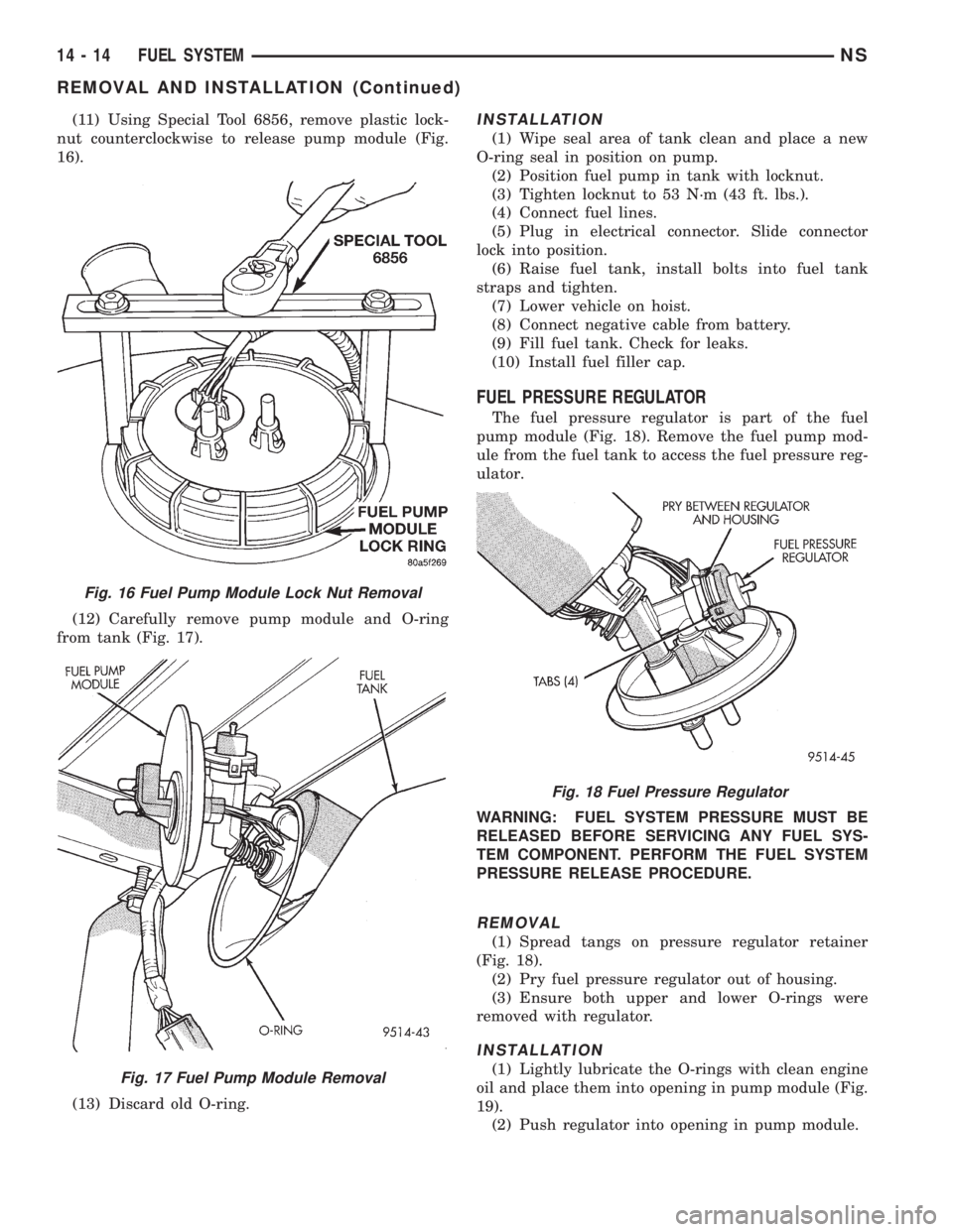
(11) Using Special Tool 6856, remove plastic lock-
nut counterclockwise to release pump module (Fig.
16).
(12) Carefully remove pump module and O-ring
from tank (Fig. 17).
(13) Discard old O-ring.INSTALLATION
(1) Wipe seal area of tank clean and place a new
O-ring seal in position on pump.
(2) Position fuel pump in tank with locknut.
(3) Tighten locknut to 53 N´m (43 ft. lbs.).
(4) Connect fuel lines.
(5) Plug in electrical connector. Slide connector
lock into position.
(6) Raise fuel tank, install bolts into fuel tank
straps and tighten.
(7) Lower vehicle on hoist.
(8) Connect negative cable from battery.
(9) Fill fuel tank. Check for leaks.
(10) Install fuel filler cap.
FUEL PRESSURE REGULATOR
The fuel pressure regulator is part of the fuel
pump module (Fig. 18). Remove the fuel pump mod-
ule from the fuel tank to access the fuel pressure reg-
ulator.
WARNING: FUEL SYSTEM PRESSURE MUST BE
RELEASED BEFORE SERVICING ANY FUEL SYS-
TEM COMPONENT. PERFORM THE FUEL SYSTEM
PRESSURE RELEASE PROCEDURE.
REMOVAL
(1) Spread tangs on pressure regulator retainer
(Fig. 18).
(2) Pry fuel pressure regulator out of housing.
(3) Ensure both upper and lower O-rings were
removed with regulator.
INSTALLATION
(1) Lightly lubricate the O-rings with clean engine
oil and place them into opening in pump module (Fig.
19).
(2) Push regulator into opening in pump module.
Fig. 16 Fuel Pump Module Lock Nut Removal
Fig. 17 Fuel Pump Module Removal
Fig. 18 Fuel Pressure Regulator
14 - 14 FUEL SYSTEMNS
REMOVAL AND INSTALLATION (Continued)
Page 1312 of 1938
INSTALLATION
(1) Position fuel tank on transmission jack. Con-
nect pressure relief/rollover valve hose. Connect fuel
filler tube vent hose and replace clamp.
(2) Raise tank into position and carefully work
filler tube into tank. A light coating of clean engine
oil on the tube end may be used to aid assembly.
(3) Feed filler vent line thru frame rail. Careful
not to cross lines.
(4) Tighten strap bolts to 54 N´m (40 ft. lbs.)
torque. Remove transmission jack.
(5) Tighten filler hose clamp to 3.3 N´m (30 in.
lbs.).
CAUTION: Ensure straps are not twisted or bent
before or after tightening strap nuts.
(6) Connect fuel pump/module electrical connector.
Place retainer in locked position.
(7) Lubricate the fuel supply line with clean 30
weight engine oil, install the quick connect fuel fit-
ting. Refer to Tube/Fitting Assembly in the Fuel
Delivery section of this Group.
(8) Attach filler line to filler tube. Pull on connec-
tor to make sure of connection.
(9) Fill fuel tank, replace cap, and connect battery
negative cable.
CAUTION: When using the ASD Fuel System Test,
the ASD relay and fuel pump relay remain energized
for 7 minutes or until the test is stopped, or until
the ignition switch is turned to the Off position.
(10) Use the DRB scan tool ASD Fuel System Test
to pressurize the fuel system. Check for leaks.
FUEL INJECTOR RAILÐ2.4L
REMOVAL
(1) Perform fuel system pressure release procedure
before servicing or starting repairs.Refer to
Fuel System Pressure Release Procedure in this sec-
tion.
(2) Disconnect negative cable from battery.
(3) Remove air cleaner inlet hose from throttle
body.
(4) Remove throttle cable and speed control cable
(if equipped) from throttle lever.
(5) Remove throttle cables from bracket by com-
pressing retaining tabs.
(6) Remove connector from throttle position sensor.
(7) Remove connector from idle air control motor.
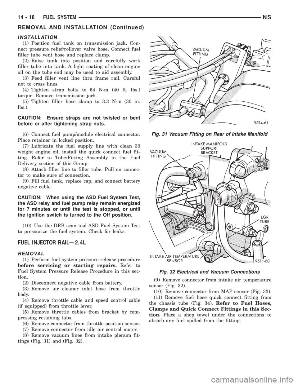
(8) Remove vacuum lines from intake plenum fit-
tings (Fig. 31) and (Fig. 32).(9) Remove connector from intake air temperature
sensor (Fig. 32).
(10) Remove connector from MAP sensor (Fig. 33).
(11) Remove fuel hose quick connect fitting from
the chassis tube (Fig. 34).Refer to Fuel Hoses,
Clamps and Quick Connect Fittings in this Sec-
tion.Place a shop towel under the connections to
absorb any fuel spilled from the fitting.
Fig. 31 Vacuum Fitting on Rear of Intake Manifold
Fig. 32 Electrical and Vacuum Connections
14 - 18 FUEL SYSTEMNS
REMOVAL AND INSTALLATION (Continued)
Page 1393 of 1938
fuel fitting. Refer to Tube/Fitting Assembly in the
Fuel Delivery section of this Group.
(7) Attach filler line to filler tube. Pull on connec-
tor to make sure of connection.
(8) Fill fuel tank, replace cap, and connect battery
negative cable.
FUEL RESERVOIR MODULE
REMOVAL
WARNING: THE FUEL RESERVOIR OF THE FUEL
MODULE DOES NOT EMPTY OUT WHEN THE TANK
IS DRAINED. THE FUEL IN THE RESERVOIR WILL
SPILL OUT WHEN THE MODULE IS REMOVED.
(1) Disconnect negative cable from battery.
(2) Insert fuel siphon hose into fuel filler neck and
push it into the tank.
(3) Drain fuel tank dry into holding tank or a
properly labeleddieselsafety container.
(4) Raise vehicle on hoist.
(5) Use a transmission jack to support the fuel
tank. Remove bolts from fuel tank straps. Lower
tank slightly.
(6) Clean area around fuel reservoir module and
tank to keep dirt and foreign material out of tank.
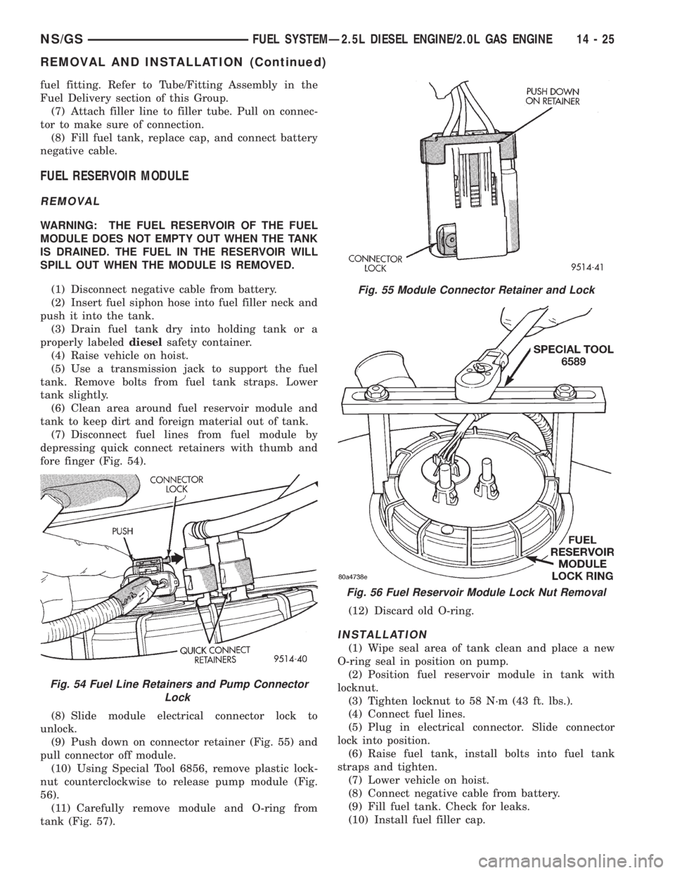
(7) Disconnect fuel lines from fuel module by
depressing quick connect retainers with thumb and
fore finger (Fig. 54).
(8) Slide module electrical connector lock to
unlock.
(9) Push down on connector retainer (Fig. 55) and
pull connector off module.
(10) Using Special Tool 6856, remove plastic lock-
nut counterclockwise to release pump module (Fig.
56).
(11) Carefully remove module and O-ring from
tank (Fig. 57).(12) Discard old O-ring.
INSTALLATION
(1) Wipe seal area of tank clean and place a new
O-ring seal in position on pump.
(2) Position fuel reservoir module in tank with
locknut.
(3) Tighten locknut to 58 N´m (43 ft. lbs.).
(4) Connect fuel lines.
(5) Plug in electrical connector. Slide connector
lock into position.
(6) Raise fuel tank, install bolts into fuel tank
straps and tighten.
(7) Lower vehicle on hoist.
(8) Connect negative cable from battery.
(9) Fill fuel tank. Check for leaks.
(10) Install fuel filler cap.
Fig. 54 Fuel Line Retainers and Pump Connector
Lock
Fig. 55 Module Connector Retainer and Lock
Fig. 56 Fuel Reservoir Module Lock Nut Removal
NS/GSFUEL SYSTEMÐ2.5L DIESEL ENGINE/2.0L GAS ENGINE 14 - 25
REMOVAL AND INSTALLATION (Continued)
Page 1436 of 1938
POWER STEERING PUMP FLOW AND
PRESSURE TEST PROCEDURE
(1) Check power steering pump drive belt tension
and adjust as necessary.
(2) Disconnect power steering fluid pressure hose,
at power steering pump. Use a container for dripping
fluid.
(3) Connect Pressure Gauge, Special Tool from kit
6815 to both hoses using adapter fittings. Connect
spare pressure hose, to power steering pump pres-
sure hose fitting.
(4) Completely open valve on Special Tool 6815.
(5) Start engine and let idle long enough to circu-
late power steering fluid through flow/pressure test
and get air out of fluid. Then shut off engine.
(6) Check power steering fluid level, and add fluid
as necessary. Start engine again and let idle.
(7) Pressure gauge should read below 862 kPa
(125 psi), if above, inspect the hoses for restrictions
and repair as necessary. The initial pressure reading
should be in the range of 345-552 kPa (50-80 psi).
The flow meter should read between 1.3 and 1.9
GPM
CAUTION: The following test procedure involves
testing power steering pump maximum pressure
output and flow control valve operation. Do not
leave valve closed for more than 5 seconds as the
pump could be damaged.
(8) Close valve fully three times and record high-
est pressure indicated each time.All three read-
ings must be within specifications and within
345 kPa (50 psi) of each other.
NOTE: Power steering pump maximum relief pres-
sure is 9653 to 10342 kPa (1400 to 1500 psi.).
²If power steering pump pressures are within the
specifications but not within 345 kPa (50 psi) of each
other, then replace power steering pump.
²If pressures are within 345 kPa (50 psi) of each
other but below specifications, then replace power
steering pump.
CAUTION: Do not force the pump to operate
against the stops for more than 5 seconds at a time
because, pump damage will result.
(9) Open test valve. Turn steering wheel to the
extreme left and right positions until against the
stops, recording the highest indicated pressure at
each position. Compare pressure gauge readings to
power steering pump specifications. If highest output
pressures are not the same against either stop, the
steering gear is leaking internally and must be
replaced.
SERVICE PROCEDURES
POWER STEERING SYSTEM FLUID LEVEL CHECK
WARNING: FLUID LEVEL SHOULD BE CHECKED
WITH ENGINE OFF TO PREVENT INJURY FROM
MOVING PARTS. DO NOT USE AUTOMATIC TRANS-
MISSION FLUID IN THE POWER STEERING SYS-
TEM. DO NOT OVERFILL THE POWER STEERING
SYSTEM.
Wipe reservoir filler cap free of dirt. Then check
fluid level. The dipstick should indicate COLD when
fluid is at normal ambient temperature, approxi-
mately 21ÉC to 27ÉC (70ÉF to 80ÉF). In all pumps add
fluid as necessary, use onlyMopar Power Steering
Fluid, or equivalent. DO NOT USE ANY TYPE
OF AUTOMATIC TRANSMISSION FLUID.
POWER STEERING PUMP INITIAL OPERATION
CAUTION: The fluid level should be checked with
engine off to prevent injury from moving compo-
nents. Use only MoparTPower Steering Fluid. Do
not use automatic transmission fluid. Do not over-
fill.
Wipe filler cap clean, then check the fluid level.
The dipstick should indicateFULL COLDwhen the
fluid is at normal temperature of approximately 21ÉC
to 27ÉC (70ÉF to 80ÉF).
(1) Fill the pump fluid reservoir to the proper level
and let the fluid settle for at least two (2) minutes.
(2) Start the engine and let run for a few seconds.
Then turn the engine off.
(3) Add fluid if necessary. Repeat the above proce-
dure until the fluid level remains constant after run-
ning the engine.
(4) Raise the front wheels off the ground.
(5) Start the engine. Slowly turn the steering
wheel right and left, lightly contacting the wheel
stops.
(6) Add power steering fluid if necessary.
(7) Lower the vehicle and turn the steering wheel
slowly from lock to lock.
(8) Stop the engine. Check the fluid level and refill
as required.
(9) If the fluid is extremely foamy, allow the vehi-
cle to stand a few minutes and repeat the above pro-
cedure.
19 - 10 STEERINGNS
DIAGNOSIS AND TESTING (Continued)
Page 1445 of 1938
cation and Maintenance section of this service man-
ual, for the required lifting procedure to be used for
this vehicle.
(5) Remove at power steering pump, the power
steering fluid hose coming from the power steering
fluid reservoir. Let the power steering fluid drain out
of the reservoir and hose.
(6) Lower vehicle.
(7) Remove hose clamp attaching the power steer-
ing fluid supply hose to the power steering fluid res-
ervoir (Fig. 24).
(8) Remove the power steering fluid supply hose
from the vehicle. Hose is removed from the top of the
engine compartment.
INSTALL
CAUTION: On V-6 engine applications, the power
steering fluid reservoir to power steering hose must
be routed tightly against the strut tower and parallel
to the dash panel. It must also be routed under the
wiring harness and below the drip tube. This rout-
ing will prevent the power steering fluid supply
hose from coming in contact with the accessory
drive belt.
(1) Install and correctly route the power steering
fluid supply hose from remote fluid reservoir down to
power steering pump.
(2) Install the fluid supply hose onto the power
steering fluid reservoir (Fig. 24). Install the hose
clamp on the fluid supply hose.Be sure hose clamp
is installed past bead on fluid reservoir fitting.
(3) Raise vehicle on jack stands or centered on a
frame contact type hoist. See Hoisting in the Lubri-
cation and Maintenance section of this service man-
ual, for the required lifting procedure to be used for
this vehicle.
(4) Install power steering fluid supply hose on
power steering pump. Install the hose clamp on the
fluid supply hose.Be sure hose clamp is installed
past bead on pump fitting.
(5) Lower vehicle.
(6) Install routing clip on power steering fluid sup-
ply hose. Be sure routing clip is installed in a posi-
tion to correctly align with stud in strut tower.
(7) Install routing clip for power steering fluid sup-
ply hose on stud in strut tower (Fig. 25).
(8) Fill the remote fluid reservoir to the proper
level and let the fluid settle for at least two (2) min-
utes.
(9) Start the engine and let run for a few seconds.
Then turn the engine off.
(10) Add fluid if necessary. Repeat the above pro-
cedure until the fluid level remains constant after
running the engine.
(11) Raise the front wheels off the ground.(12) Start the engine. Slowly turn the steering
wheel right and left, lightly contacting the wheel
stops.
(13) Add power steering fluid if necessary.
(14) Lower the vehicle and turn the steering wheel
slowly from lock to lock.
(15) Stop the engine. Check the fluid level and
refill as required.
(16) If the fluid is extremely foamy, allow the vehi-
cle to stand a few minutes and repeat the above pro-
cedure.
POWER STEERING FLUID PRESSURE HOSE
Service all power steering hoses with vehicle raised
on hoist. Cap all open ends of hoses, power steering
pump fittings and steering gear ports to prevent
entry of foreign material into the components.
WARNING: POWER STEERING OIL, ENGINE
PARTS AND THE EXHAUST SYSTEM MAY BE
EXTREMELY HOT IF ENGINE HAS BEEN RUNNING.
DO NOT START ENGINE WITH ANY LOOSE OR DIS-
CONNECTED HOSES. DO NOT ALLOW HOSES TO
TOUCH HOT EXHAUST MANIFOLD OR CATALYST.
For part reference and part location for the vehicle
that is being serviced, refer to the following figure
numbers. These show the hose bracket locations,
hose routings and fitting locations by the engine
application of the vehicle. Use these figure numbers
when referring to the removal or installation proce-
dures for the power steering hoses listed below.
REMOVE
(1) Remove cap from power steering fluid reser-
voir.
(2) Using a siphon pump, remove as much power
steering fluid as possible from the power steering
fluid reservoir.
(3) Raise vehicle See Hoisting, Group 0. Put oil
drain pan under vehicle to catch power steering fluid.
(4) Raise the heat sleeve on the power steering
fluid return hose (Fig. 26) to expose the return hose
to steel tube connection. Remove the hose clamp from
the power steering fluid return hose (Fig. 26).
Remove power steering fluid return hose from steel
tube and allow power steering fluid to drain from
pump.
NSSTEERING 19 - 19
REMOVAL AND INSTALLATION (Continued)