1996 CHRYSLER VOYAGER check engine light
[x] Cancel search: check engine lightPage 1112 of 1938
front seal is retained in the oil pump case and the
rear is retained in a block-mounted housing.
PISTONS:Are aluminum alloy with a steel strut,
short height, and thin wall so as to be autothermic
and light weight. The piston head with valve
recesses, in combination with the cylinder head,
forms a compact spherical head with clearance for
total valve lift with pistons at top dead center. The
piston skirt, top and second ring lands are finished to
a tapered roughness for oil retention and high resis-
tance to scuffing. Piston pins, pressed into place, join
the pistons to the connecting rods.
CYLINDER HEAD:The alloy cylinder heads fea-
ture cross-flow type intake and exhaust ports. Valve
guides and inserts are hardened cast iron. Valves of
heat resistance steel are arranged in a V with each
camshaft on center. To improve combustion speed the
chambers are a compact spherical design with a
squish area of approximately 30 percent of the piston
top area. The cylinder heads are common to either
cylinder bank by reversing the direction of installa-
tion.
CAMSHAFTS:Two overhead camshafts provide
valve actuation, one front (radiator side of cylinder
bank) and one rear. The front camshaft is provided
with a distributor drive and is longer. Both cam-
shafts are supported by four bearing journals, thrust
for the front camshaft is taken at journal two and
the rear at journal three. Front and rear camshaft
driving sprockets are interchangeable. The sprockets
and the engine water pump are driven by a single
notched timing belt.
ROCKER ARM SHAFTS:The shafts are retained
by the camshaft bearing journal caps. Four shafts are
used, one for each intake and exhaust rocker arm
assembly on each cylinder head. The hollow shafts
provide a duct for lubricating oil flow from the cylin-
der head to the valve mechanisms.
ROCKER ARMS:Are of light weight die-cast with
roller type follower operating against the cam shaft.
The valve actuating end of the rocker arms are
machined to retain hydraulic lash adjusters, elimi-
nating valve lash adjustment.
VALVES:Are made of heat resistant steel, valve
springs are especially designed to be short. The valve
spring wire cross-section is oval shaped and provides
the same spring tension as longer springs. Valve
spring retainers, locks and seals are conventional.
INTAKE MANIFOLD:The aluminum alloy mani-
fold is a cross type with long runners to improve
inertia. The runners, attaching below at the cylinder
head, also attach above and support an air plenum.
The air plenum chamber absorbs air pulsations cre-
ated during the suction phase of each cylinder.
EXHAUST MANIFOLDS:Both manifolds are a
log style made of ductile cast iron. Exhaust gasses,collected from the front cylinder bank, leave the front
manifold through an end outlet and are fed through
an upper crossover tube to the rear manifold. The
collected exhaust from both manifolds are combined,
and exit to the exhaust pipe through an articulated
joint.
DIAGNOSIS AND TESTING
CHECKING ENGINE OIL PRESSURE
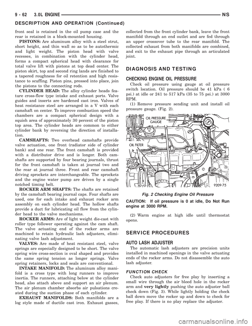
Check oil pressure using gauge at oil pressure
switch location. Oil pressure should be 41 kPa ( 6
psi.) at idle or 241 to 517 kPa (35 to 75 psi.) at 3000
RPM.
(1) Remove pressure sending unit and install oil
pressure gauge. (Fig. 2).
CAUTION: If oil pressure is 0 at idle, Do Not Run
engine at 3000 RPM.
(2) Warm engine at high idle until thermostat
opens.
SERVICE PROCEDURES
AUTO LASH ADJUSTER
The automatic lash adjusters are precision units
installed in machined openings in the valve actuating
ends of the rocker arms. Do not disassemble the auto
lash adjuster.
FUNCTION CHECK
Check auto adjusters for free play by inserting a
small wire through the air bleed hole in the rocker
arm andvery lightlypushing the auto adjuster ball
check down (Fig. 3). While lightly holding the check
ball down move the rocker up and down to check for
free play. If there is no play replace the adjuster.
Fig. 2 Checking Engine Oil Pressure
9 - 62 3.0L ENGINENS
DESCRIPTION AND OPERATION (Continued)
Page 1146 of 1938
NOTE: Worn valve guides or cocked springs are
sometimes mistaken for noisy tappets. If such is
the case, noise may be dampened by applying side
thrust on the valve spring. If noise is not apprecia-
bly reduced, it can be assumed the noise is in the
tappet. Inspect the rocker arm push rod sockets
and push rod ends for wear.
Valve tappet noise ranges from light noise to a
heavy click. A light noise is usually caused by exces-
sive leak-down around the unit plunger which will
necessitate replacing the tappet, or by the plunger
partially sticking in the tappet body cylinder. A heavy
click is caused either by a tappet check valve not
seating, or by foreign particles becoming wedged
between the plunger and the tappet body causing the
plunger to stick in the down position. This heavy
click will be accompanied by excessive clearance
between the valve stem and rocker arm as valve
closes. In either case, tappet assembly should be
removed for inspection and cleaning.
CHECKING ENGINE OIL PRESSURE
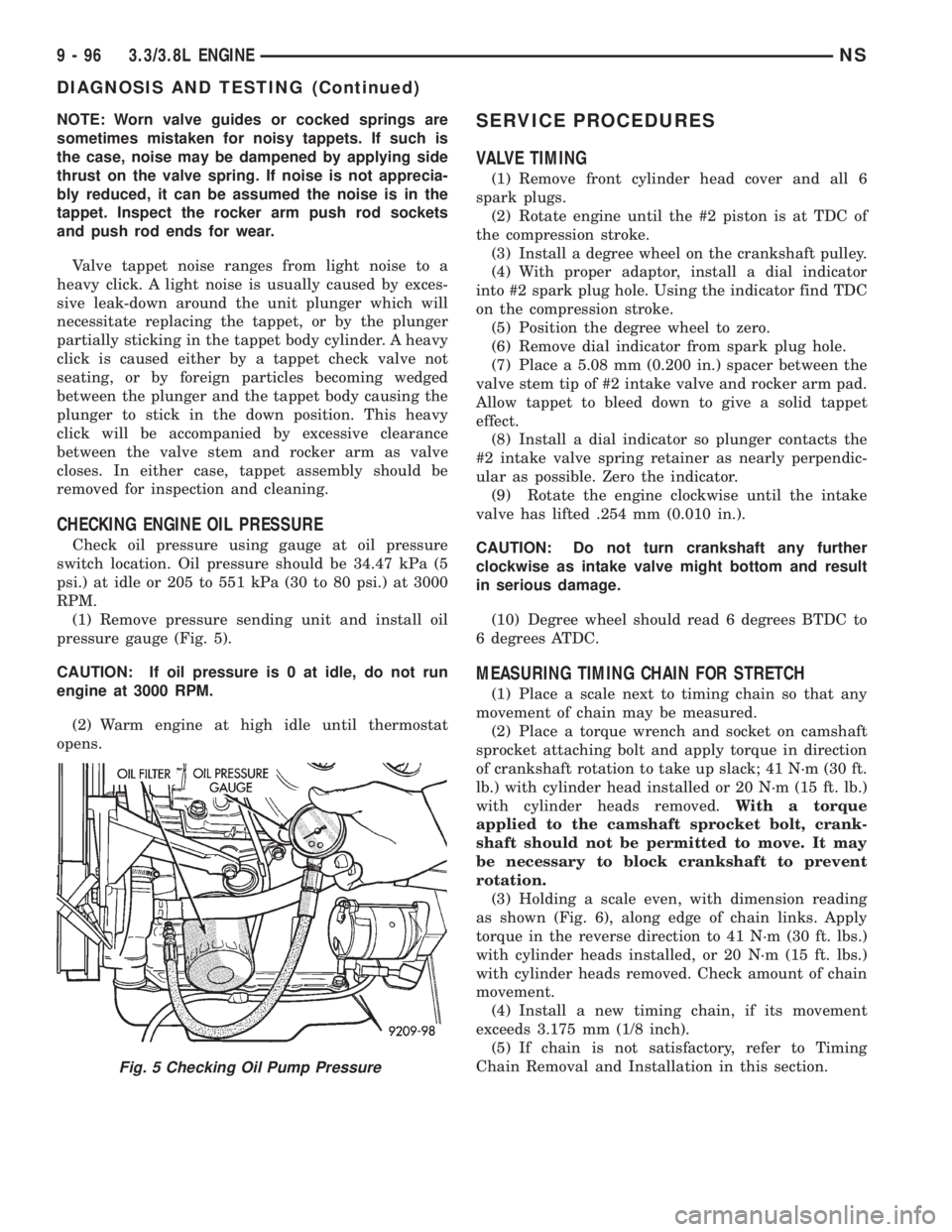
Check oil pressure using gauge at oil pressure
switch location. Oil pressure should be 34.47 kPa (5
psi.) at idle or 205 to 551 kPa (30 to 80 psi.) at 3000
RPM.
(1) Remove pressure sending unit and install oil
pressure gauge (Fig. 5).
CAUTION: If oil pressure is 0 at idle, do not run
engine at 3000 RPM.
(2) Warm engine at high idle until thermostat
opens.
SERVICE PROCEDURES
VALVE TIMING
(1) Remove front cylinder head cover and all 6
spark plugs.
(2) Rotate engine until the #2 piston is at TDC of
the compression stroke.
(3) Install a degree wheel on the crankshaft pulley.
(4) With proper adaptor, install a dial indicator
into #2 spark plug hole. Using the indicator find TDC
on the compression stroke.
(5) Position the degree wheel to zero.
(6) Remove dial indicator from spark plug hole.
(7) Place a 5.08 mm (0.200 in.) spacer between the
valve stem tip of #2 intake valve and rocker arm pad.
Allow tappet to bleed down to give a solid tappet
effect.
(8) Install a dial indicator so plunger contacts the
#2 intake valve spring retainer as nearly perpendic-
ular as possible. Zero the indicator.
(9) Rotate the engine clockwise until the intake
valve has lifted .254 mm (0.010 in.).
CAUTION: Do not turn crankshaft any further
clockwise as intake valve might bottom and result
in serious damage.
(10) Degree wheel should read 6 degrees BTDC to
6 degrees ATDC.
MEASURING TIMING CHAIN FOR STRETCH
(1) Place a scale next to timing chain so that any
movement of chain may be measured.
(2) Place a torque wrench and socket on camshaft
sprocket attaching bolt and apply torque in direction
of crankshaft rotation to take up slack; 41 N´m (30 ft.
lb.) with cylinder head installed or 20 N´m (15 ft. lb.)
with cylinder heads removed.With a torque
applied to the camshaft sprocket bolt, crank-
shaft should not be permitted to move. It may
be necessary to block crankshaft to prevent
rotation.
(3) Holding a scale even, with dimension reading
as shown (Fig. 6), along edge of chain links. Apply
torque in the reverse direction to 41 N´m (30 ft. lbs.)
with cylinder heads installed, or 20 N´m (15 ft. lbs.)
with cylinder heads removed. Check amount of chain
movement.
(4) Install a new timing chain, if its movement
exceeds 3.175 mm (1/8 inch).
(5) If chain is not satisfactory, refer to Timing
Chain Removal and Installation in this section.
Fig. 5 Checking Oil Pump Pressure
9 - 96 3.3/3.8L ENGINENS
DIAGNOSIS AND TESTING (Continued)
Page 1169 of 1938
Install new gasket and tighten screws to 12 N´m (105
in. lbs.).
OIL FILTER
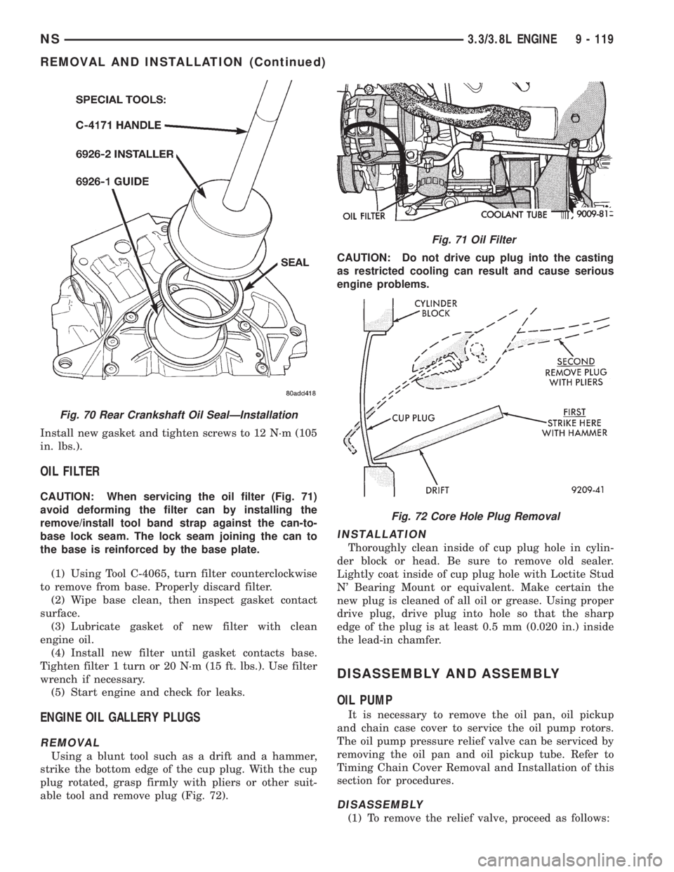
CAUTION: When servicing the oil filter (Fig. 71)
avoid deforming the filter can by installing the
remove/install tool band strap against the can-to-
base lock seam. The lock seam joining the can to
the base is reinforced by the base plate.
(1) Using Tool C-4065, turn filter counterclockwise
to remove from base. Properly discard filter.
(2) Wipe base clean, then inspect gasket contact
surface.
(3) Lubricate gasket of new filter with clean
engine oil.
(4) Install new filter until gasket contacts base.
Tighten filter 1 turn or 20 N´m (15 ft. lbs.). Use filter
wrench if necessary.
(5) Start engine and check for leaks.
ENGINE OIL GALLERY PLUGS
REMOVAL
Using a blunt tool such as a drift and a hammer,
strike the bottom edge of the cup plug. With the cup
plug rotated, grasp firmly with pliers or other suit-
able tool and remove plug (Fig. 72).CAUTION: Do not drive cup plug into the casting
as restricted cooling can result and cause serious
engine problems.
INSTALLATION
Thoroughly clean inside of cup plug hole in cylin-
der block or head. Be sure to remove old sealer.
Lightly coat inside of cup plug hole with Loctite Stud
N' Bearing Mount or equivalent. Make certain the
new plug is cleaned of all oil or grease. Using proper
drive plug, drive plug into hole so that the sharp
edge of the plug is at least 0.5 mm (0.020 in.) inside
the lead-in chamfer.
DISASSEMBLY AND ASSEMBLY
OIL PUMP
It is necessary to remove the oil pan, oil pickup
and chain case cover to service the oil pump rotors.
The oil pump pressure relief valve can be serviced by
removing the oil pan and oil pickup tube. Refer to
Timing Chain Cover Removal and Installation of this
section for procedures.
DISASSEMBLY
(1) To remove the relief valve, proceed as follows:
Fig. 70 Rear Crankshaft Oil SealÐInstallation
Fig. 71 Oil Filter
Fig. 72 Core Hole Plug Removal
NS3.3/3.8L ENGINE 9 - 119
REMOVAL AND INSTALLATION (Continued)
Page 1170 of 1938
(2) Drill a 3.175 mm (1/8 inch) hole into the relief
valve retainer cap and insert a self-threading sheet
metal screw into cap.
(3) Clamp screw into a vise and while supporting
chain case cover, remove cap by tapping chain case
cover using a soft hammer. Discard retainer cap and
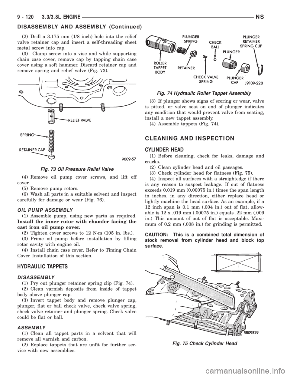
remove spring and relief valve (Fig. 73).
(4) Remove oil pump cover screws, and lift off
cover.
(5) Remove pump rotors.
(6) Wash all parts in a suitable solvent and inspect
carefully for damage or wear (Fig. 76).
OIL PUMP ASSEMBLY
(1) Assemble pump, using new parts as required.
Install the inner rotor with chamfer facing the
cast iron oil pump cover.
(2) Tighten cover screws to 12 N´m (105 in. lbs.).
(3) Prime oil pump before installation by filling
rotor cavity with engine oil.
(4) Install chain case cover. Refer to Timing Chain
Cover Installation of this section.
HYDRAULIC TAPPETS
DISASSEMBLY
(1) Pry out plunger retainer spring clip (Fig. 74).
(2) Clean varnish deposits from inside of tappet
body above plunger cap.
(3) Invert tappet body and remove plunger cap,
plunger, flat or ball check valve, check valve spring,
check valve retainer and plunger spring. Check valve
could be flat or ball.
ASSEMBLY
(1) Clean all tappet parts in a solvent that will
remove all varnish and carbon.
(2) Replace tappets that are unfit for further ser-
vice with new assemblies.(3) If plunger shows signs of scoring or wear, valve
is pitted, or valve seat on end of plunger indicates
any condition that would prevent valve from seating,
install a new tappet assembly.
(4) Assemble tappets (Fig. 74).
CLEANING AND INSPECTION
CYLINDER HEAD
(1) Before cleaning, check for leaks, damage and
cracks.
(2) Clean cylinder head and oil passages.
(3) Check cylinder head for flatness (Fig. 75).
(4) Inspect all surfaces with a straightedge if there
is any reason to suspect leakage. If out of flatness
exceeds 0.019 mm (0.00075 in.) times the span length
in inches, in any direction, either replace head or
lightly machine the head surface. As an example, if a
12 inch span is 0.1 mm (.004 in.) out of flat, allow-
able is 12 x .019 mm (.00075 in.) equals .22 mm (.009
in.) This amount of out of flat is acceptable. Maxi-
mum of 0.2 mm (.008 in.) for grinding is permitted.
CAUTION: This is a combined total dimension of
stock removal from cylinder head and block top
surface.
Fig. 73 Oil Pressure Relief Valve
Fig. 74 Hydraulic Roller Tappet Assembly
Fig. 75 Check Cylinder Head
9 - 120 3.3/3.8L ENGINENS
DISASSEMBLY AND ASSEMBLY (Continued)
Page 1185 of 1938
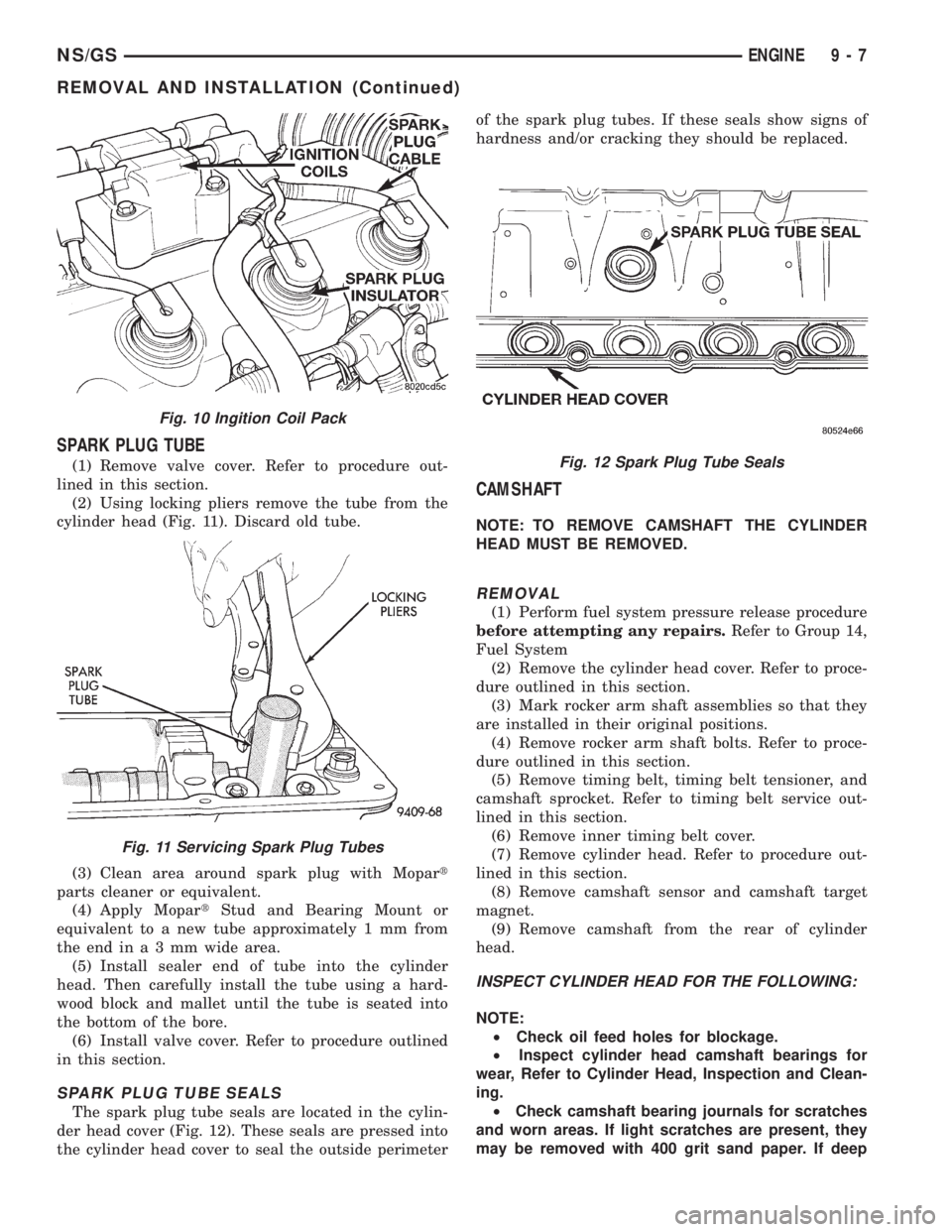
SPARK PLUG TUBE
(1) Remove valve cover. Refer to procedure out-
lined in this section.
(2) Using locking pliers remove the tube from the
cylinder head (Fig. 11). Discard old tube.
(3) Clean area around spark plug with Mopart
parts cleaner or equivalent.
(4) Apply MopartStud and Bearing Mount or
equivalent to a new tube approximately 1 mm from
theendina3mmwide area.
(5) Install sealer end of tube into the cylinder
head. Then carefully install the tube using a hard-
wood block and mallet until the tube is seated into
the bottom of the bore.
(6) Install valve cover. Refer to procedure outlined
in this section.
SPARK PLUG TUBE SEALS
The spark plug tube seals are located in the cylin-
der head cover (Fig. 12). These seals are pressed into
the cylinder head cover to seal the outside perimeterof the spark plug tubes. If these seals show signs of
hardness and/or cracking they should be replaced.
CAMSHAFT
NOTE: TO REMOVE CAMSHAFT THE CYLINDER
HEAD MUST BE REMOVED.
REMOVAL
(1) Perform fuel system pressure release procedure
before attempting any repairs.Refer to Group 14,
Fuel System
(2) Remove the cylinder head cover. Refer to proce-
dure outlined in this section.
(3) Mark rocker arm shaft assemblies so that they
are installed in their original positions.
(4) Remove rocker arm shaft bolts. Refer to proce-
dure outlined in this section.
(5) Remove timing belt, timing belt tensioner, and
camshaft sprocket. Refer to timing belt service out-
lined in this section.
(6) Remove inner timing belt cover.
(7) Remove cylinder head. Refer to procedure out-
lined in this section.
(8) Remove camshaft sensor and camshaft target
magnet.
(9) Remove camshaft from the rear of cylinder
head.
INSPECT CYLINDER HEAD FOR THE FOLLOWING:
NOTE:
²Check oil feed holes for blockage.
²Inspect cylinder head camshaft bearings for
wear, Refer to Cylinder Head, Inspection and Clean-
ing.
²Check camshaft bearing journals for scratches
and worn areas. If light scratches are present, they
may be removed with 400 grit sand paper. If deep
Fig. 10 Ingition Coil Pack
Fig. 11 Servicing Spark Plug Tubes
Fig. 12 Spark Plug Tube Seals
NS/GSENGINE 9 - 7
REMOVAL AND INSTALLATION (Continued)
Page 1194 of 1938
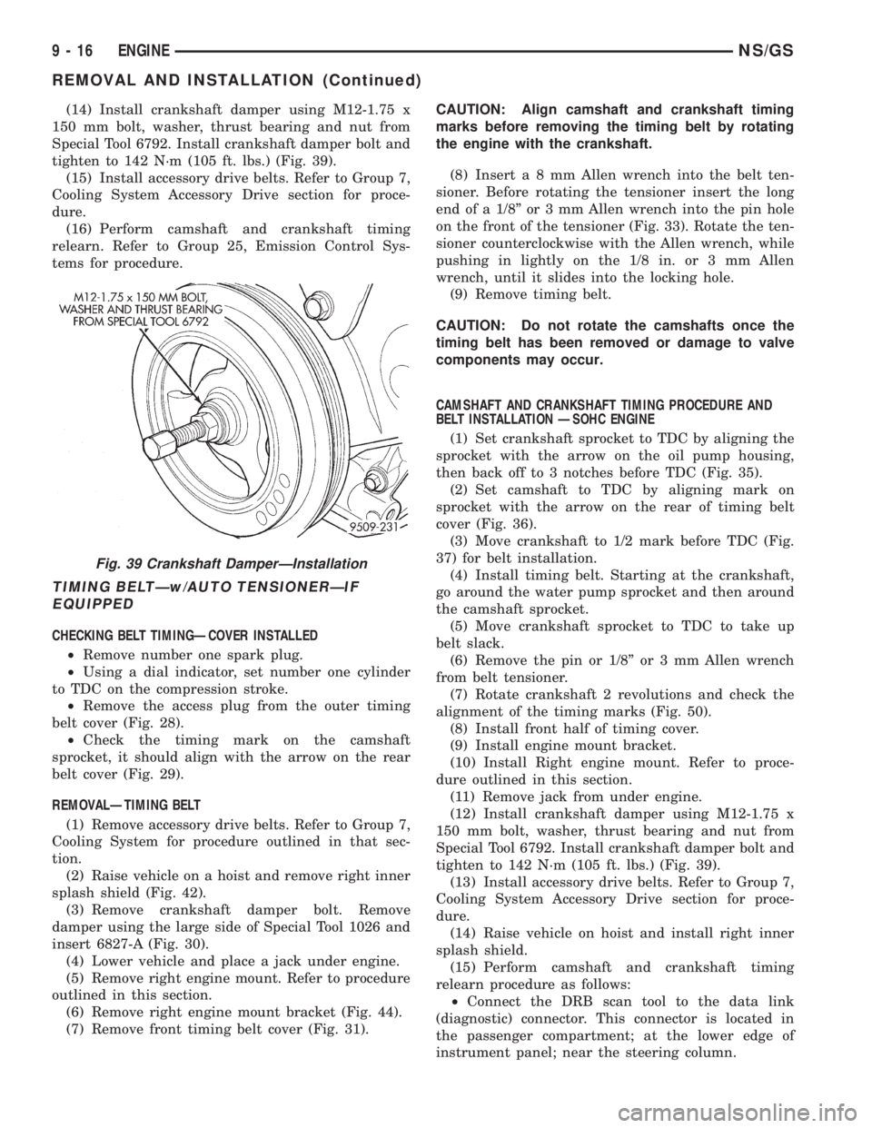
(14) Install crankshaft damper using M12-1.75 x
150 mm bolt, washer, thrust bearing and nut from
Special Tool 6792. Install crankshaft damper bolt and
tighten to 142 N´m (105 ft. lbs.) (Fig. 39).
(15) Install accessory drive belts. Refer to Group 7,
Cooling System Accessory Drive section for proce-
dure.
(16) Perform camshaft and crankshaft timing
relearn. Refer to Group 25, Emission Control Sys-
tems for procedure.
TIMING BELTÐw/AUTO TENSIONERÐIF
EQUIPPED
CHECKING BELT TIMINGÐCOVER INSTALLED
²Remove number one spark plug.
²Using a dial indicator, set number one cylinder
to TDC on the compression stroke.
²Remove the access plug from the outer timing
belt cover (Fig. 28).
²Check the timing mark on the camshaft
sprocket, it should align with the arrow on the rear
belt cover (Fig. 29).
REMOVALÐTIMING BELT
(1) Remove accessory drive belts. Refer to Group 7,
Cooling System for procedure outlined in that sec-
tion.
(2) Raise vehicle on a hoist and remove right inner
splash shield (Fig. 42).
(3) Remove crankshaft damper bolt. Remove
damper using the large side of Special Tool 1026 and
insert 6827-A (Fig. 30).
(4) Lower vehicle and place a jack under engine.
(5) Remove right engine mount. Refer to procedure
outlined in this section.
(6) Remove right engine mount bracket (Fig. 44).
(7) Remove front timing belt cover (Fig. 31).CAUTION: Align camshaft and crankshaft timing
marks before removing the timing belt by rotating
the engine with the crankshaft.
(8) Inserta8mmAllen wrench into the belt ten-
sioner. Before rotating the tensioner insert the long
end of a 1/8º or 3 mm Allen wrench into the pin hole
on the front of the tensioner (Fig. 33). Rotate the ten-
sioner counterclockwise with the Allen wrench, while
pushing in lightly on the 1/8 in. or 3 mm Allen
wrench, until it slides into the locking hole.
(9) Remove timing belt.
CAUTION: Do not rotate the camshafts once the
timing belt has been removed or damage to valve
components may occur.
CAMSHAFT AND CRANKSHAFT TIMING PROCEDURE AND
BELT INSTALLATION ÐSOHC ENGINE
(1) Set crankshaft sprocket to TDC by aligning the
sprocket with the arrow on the oil pump housing,
then back off to 3 notches before TDC (Fig. 35).
(2) Set camshaft to TDC by aligning mark on
sprocket with the arrow on the rear of timing belt
cover (Fig. 36).
(3) Move crankshaft to 1/2 mark before TDC (Fig.
37) for belt installation.
(4) Install timing belt. Starting at the crankshaft,
go around the water pump sprocket and then around
the camshaft sprocket.
(5) Move crankshaft sprocket to TDC to take up
belt slack.
(6) Remove the pin or 1/8º or 3 mm Allen wrench
from belt tensioner.
(7) Rotate crankshaft 2 revolutions and check the
alignment of the timing marks (Fig. 50).
(8) Install front half of timing cover.
(9) Install engine mount bracket.
(10) Install Right engine mount. Refer to proce-
dure outlined in this section.
(11) Remove jack from under engine.
(12) Install crankshaft damper using M12-1.75 x
150 mm bolt, washer, thrust bearing and nut from
Special Tool 6792. Install crankshaft damper bolt and
tighten to 142 N´m (105 ft. lbs.) (Fig. 39).
(13) Install accessory drive belts. Refer to Group 7,
Cooling System Accessory Drive section for proce-
dure.
(14) Raise vehicle on hoist and install right inner
splash shield.
(15) Perform camshaft and crankshaft timing
relearn procedure as follows:
²Connect the DRB scan tool to the data link
(diagnostic) connector. This connector is located in
the passenger compartment; at the lower edge of
instrument panel; near the steering column.
Fig. 39 Crankshaft DamperÐInstallation
9 - 16 ENGINENS/GS
REMOVAL AND INSTALLATION (Continued)
Page 1209 of 1938
Total runout should not exceed. 0.051 mm (0.002
inch.) (total indicator reading).
(5) Inspect the valve seat with Prussian blue to
determine where the valve contacts the seat. To do
this, coat valve seatLIGHTLYwith Prussian blue
then set valve in place. Rotate the valve with light
pressure. If the blue is transferred to the center of
valve face, contact is satisfactory. If the blue is trans-
ferred to top edge of the valve face, lower valve seat
with a 15 degrees stone. If the blue is transferred to
the bottom edge of valve face raise valve seat with a
65 degrees stone.
²Intake valve seat diameter is 33 mm (1.299 in.)
²Exhaust valve seat diameter is 28 mm (1.102
in.)
(6) Valve seats which are worn or burned can be
reworked, provided that correct angle and seat width
are maintained. The intake valve seat must be ser-
viced when the valve seat width is 2.0 mm (0.079 in.)
or greater. The exhaust valve seat must be serviced
when the valve seat width is 2.5 mm (0.098 in.) or
greater. Otherwise the cylinder head must be
replaced.
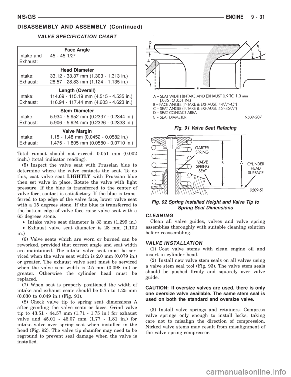
(7) When seat is properly positioned the width of
intake and exhaust seats should be 0.75 to 1.25 mm
(0.030 to 0.049 in.) (Fig. 91).
(8) Check valve tip to spring seat dimensions A
after grinding the valve seats or faces. Grind valve
tip to 43.51 - 44.57 mm (1.71 - 1.75 in.) for exhaust
valve and 45.01 - 46.07 mm (1.77 - 1.81 in.) for
intake valve over spring seat when installed in the
head (Fig. 92). The valve tip chamfer may need to be
reground to prevent seal damage when the valve is
installed.
CLEANING
Clean all valve guides, valves and valve spring
assemblies thoroughly with suitable cleaning solution
before reassembling.
VALVE INSTALLATION
(1) Coat valve stems with clean engine oil and
insert in cylinder head.
(2) Install new valve stem seals on all valves using
a valve stem seal tool (Fig. 93). The valve stem seals
should be pushed firmly and squarely over valve
guide.
CAUTION: If oversize valves are used, there is only
one oversize valve available. The same stem seal is
used on both the standard and oversize valve.
(3) Install valve springs and retainers. Compress
valve springs only enough to install locks, taking
care not to misalign the direction of compression.
Nicked valve stems may result from misalignment of
the valve spring compressor.
VALVE SPECIFICATION CHART
Face Angle
Intake and
Exhaust:45 - 45 1/2É
Head Diameter
Intake: 33.12 - 33.37 mm (1.303 - 1.313 in.)
Exhaust: 28.57 - 28.83 mm (1.124 - 1.135 in.)
Length (Overall)
Intake: 114.69 - 115.19 mm (4.515 - 4.535 in.)
Exhaust: 116.94 - 117.44 mm (4.603 - 4.623 in.)
Stem Diameter
Intake: 5.934 - 5.952 mm (0.2337 - 0.2344 in.)
Exhaust: 5.906 - 5.924 mm (0.2326 - 0.2333 in.)
Valve Margin
Intake: 1.15 - 1.48 mm (0.0452 - 0.0582 in.)
Exhaust: 1.475 - 1.805 mm (0.0580 - 0.0710 in.)
Fig. 91 Valve Seat Refacing
Fig. 92 Spring Installed Height and Valve Tip to
Spring Seat Dimensions
NS/GSENGINE 9 - 31
DISASSEMBLY AND ASSEMBLY (Continued)
Page 1210 of 1938
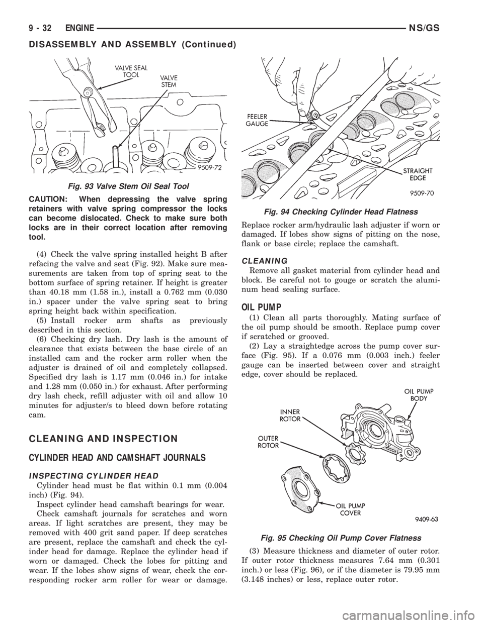
CAUTION: When depressing the valve spring
retainers with valve spring compressor the locks
can become dislocated. Check to make sure both
locks are in their correct location after removing
tool.
(4) Check the valve spring installed height B after
refacing the valve and seat (Fig. 92). Make sure mea-
surements are taken from top of spring seat to the
bottom surface of spring retainer. If height is greater
than 40.18 mm (1.58 in.), install a 0.762 mm (0.030
in.) spacer under the valve spring seat to bring
spring height back within specification.
(5) Install rocker arm shafts as previously
described in this section.
(6) Checking dry lash. Dry lash is the amount of
clearance that exists between the base circle of an
installed cam and the rocker arm roller when the
adjuster is drained of oil and completely collapsed.
Specified dry lash is 1.17 mm (0.046 in.) for intake
and 1.28 mm (0.050 in.) for exhaust. After performing
dry lash check, refill adjuster with oil and allow 10
minutes for adjuster/s to bleed down before rotating
cam.
CLEANING AND INSPECTION
CYLINDER HEAD AND CAMSHAFT JOURNALS
INSPECTING CYLINDER HEAD
Cylinder head must be flat within 0.1 mm (0.004
inch) (Fig. 94).
Inspect cylinder head camshaft bearings for wear.
Check camshaft journals for scratches and worn
areas. If light scratches are present, they may be
removed with 400 grit sand paper. If deep scratches
are present, replace the camshaft and check the cyl-
inder head for damage. Replace the cylinder head if
worn or damaged. Check the lobes for pitting and
wear. If the lobes show signs of wear, check the cor-
responding rocker arm roller for wear or damage.Replace rocker arm/hydraulic lash adjuster if worn or
damaged. If lobes show signs of pitting on the nose,
flank or base circle; replace the camshaft.
CLEANING
Remove all gasket material from cylinder head and
block. Be careful not to gouge or scratch the alumi-
num head sealing surface.
OIL PUMP
(1) Clean all parts thoroughly. Mating surface of
the oil pump should be smooth. Replace pump cover
if scratched or grooved.
(2) Lay a straightedge across the pump cover sur-
face (Fig. 95). If a 0.076 mm (0.003 inch.) feeler
gauge can be inserted between cover and straight
edge, cover should be replaced.
(3) Measure thickness and diameter of outer rotor.
If outer rotor thickness measures 7.64 mm (0.301
inch.) or less (Fig. 96), or if the diameter is 79.95 mm
(3.148 inches) or less, replace outer rotor.
Fig. 93 Valve Stem Oil Seal Tool
Fig. 94 Checking Cylinder Head Flatness
Fig. 95 Checking Oil Pump Cover Flatness
9 - 32 ENGINENS/GS
DISASSEMBLY AND ASSEMBLY (Continued)